Event management architecture for the monitoring and diagnosis of a fleet of trains: a case study
Adoum Fadil · Damien Trentesaux· Guillaume Branger
Abstract In recent years, more and more manufacturers and operators of fleets of mobile systems have been focusing their efforts on studying and developing conditional maintenance, monitoring, and diagnostic strategies to cope with an increasingly competitive, unstable, costly,and unpredictable environment. This paper proposes a case study concerning the application of a novel event management architecture, called EMH2, to a fleet of trains. This EMH2 architecture, which applies the holonic paradigm, aims to facilitate the monitoring and diagnosis of a fleet of mobile systems. It is based on a recursive decomposition of cooperative monitoring holons. The definition of a generic event modeling, called SurfEvent,is the second key element of the contribution. EMH2 has been designed to be applicable to any kind of system or equipment up to fleet level.The edge computing paradigm has been adopted for implementation purpose. The EMH2 architecture is designed to facilitate asynchronous and progressive onboard and off-board deployments. A realworld application of EMH2 to a fleet of ten trains currently in use, in collaboration with our industrial partner,Bombardier Transport, is presented. Three key performances indicators have been estimated by comparing EMH2 with the current industrial situation. These indicators are (1) the number of fleet maintenance visits, (2)the time needed by a maintenance operator to investigate and diagnose, and (3) the time needed by the system to update data regarding the health status and monitoring of trains. Results obtained outperformed industrial expectations. The paper finally discusses feedbacks from experience and limitations of the work.
Keywords Event management system · Holonic architecture · Monitoring · Diagnosis · Condition-based maintenance · Rail transportation
1 Introduction
Today, despite advances in information and communication technology, as well as the widespread integration of automated functions into embedded systems to provide new services and meet even higher expectations in terms of safety and reliability [1], monitoring, diagnosis, and maintenance of fleets of mobile systems (e.g., trains) are still very important. Moreover, the whole process is still largely manual, executed by operators who have very few effective tools to help them. Managing a large amount of information in these conditions, along with the need to react quickly, can result in operators making inefficient or even incorrect decisions, thus further degrading the situation[2].In recent years,more and more manufacturers and operators in the rail transportation sector have been focusing their efforts on studying and developing event management systems to improve diagnosis and monitoring processes. The effectiveness of these event management systems is described not only in terms of responsiveness,flexibility, and reliability, but also in terms of their ability to adapt to an increasingly competitive, unstable, costly,and unpredictable environment [3].
This work deals with architecting event management processes to improve the monitoring and diagnosis functions of each mobile system in a fleet and thus improve the condition-based maintenance (CBM) of the entire fleet. In this paper, monitoring is defined as the process of collecting,analyzing,and signaling events,from their sources to their impacts. Diagnosis is defined as the process enabling the memorization,handling,and understanding of dependencies between events, as well as their causes and consequences on system availability [4]. The correct handling of these events thus constitutes a key enabler to render monitoring and diagnosis functions efficient, reactive, and adaptable. An event is defined as a time-stamped change of state or variable in a system (detected or not).Events are key elements,as monitoring and diagnosis data,and information and knowledge flows are triggered, processed, stored, and communicated as a result of their occurrence. Industrialists in the rail transportation sector understand that improvements in fleet CBM are currently hindered at event management level [5]. Additionally, the complexity of a fleet of mobile systems (e.g., trains integrating a set of mechatronic, multi-level, and networked equipment),scattered over a large geographical area during use,generates major issues to be resolved in order to design an effective fleet event management system.
In this work, we focus on the event management architectures on which such fleet event management systems rely. An event management architecture is defined as a computerized system integrating the functions and algorithms(software)to be supported,as well as the location of the different computing elements (hardware) in charge of the flow of events, information, and digitalized knowledge[6].
We propose an original event management architecture based on the holonic principles called EMH2. This architecture aims to improve the monitoring and diagnostic processes of a fleet of mobile systems in order to design an effective event management system. A real-world application to a fleet of ten trains currently in use is presented as a case study, from which some limitations have been identified.
The paper is organized as follows: First, the context of the study, including a review of the literature, is proposed in Sect. 2.Then,the EMH2event management architecture is presented in Sect. 3. Methodological aspects are discussed in Sect. 4. A description of the case study is provided in Sect. 5. Finally, the main points of this paper are summarized in the conclusion.
2 Context of the study
2.1 Subject
We consider a fleet of homogeneous mobile systems, typically a fleet of trains, but other modes of transportation may be concerned. Each mobile system is composed of a set of distributed, networked, and onboard equipment,hereinafter referred to as a system. A system is organized and controlled according to a hierarchical structure, from top level(e.g.,a train)to low level(e.g.,mechatronic part),including intermediary levels [e.g., equipment: door,heating, ventilation, and air conditioning (HVAC), etc.]. It is assumed that these mobile systems are maintained by a ground maintenance center (MC) connected to the fleet(e.g., using Internet-based communication systems). The MC is in charge of planning and optimizing the overall cost of maintenance operations. Figure 1 schematizes this organization.
Today, a major issue faced by industrialists and operators of fleets of mobile systems is how to manage and improve the monitoring and diagnosis of the latter in which information, reasoning, decision, and optimization processes are based on multiple sources of events and data in a distributed environment while also considering the specificities, locations, and various usages of these numerous mobile systems. This question addresses major issues such as the management and optimization of maintenance costs,the reliability of maintenance tasks, the responsiveness of the monitoring system,and its ability to learn and adapt to new or overhauled equipment. Indeed, fleet maintainers often have to cope with huge quantities of monitoring and diagnosis events,data(data bursts),and information,which often lack accuracy and contextual information and are even sometimes contradictory or obsolete. Finally, their degree of urgency is rarely addressed. The maintainer is frequently informed too late that a critical breakdown has occurred; otherwise, it could have been avoided with a more accurate, precise, and reactive management of precursor events generated by the critical equipment.
Resolving this issue is thus complex and involves several dimensions: technological, organizational, and financial [7]. This paper addresses the technological dimension of event management architectures with the aim of improving the monitoring and diagnosis of a fleet of mobile systems.
From our perspective, the performance of a fleet event management architecture can be described by different indicators related to:
· cost (e.g., the number of maintenance visits per week),
· time (e.g., the time needed to investigate and diagnose and then file a report relating to an operation or the timeneeded for the event management architecture to update data regarding equipment and mobile system health status),
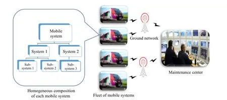
Fig. 1 Fleet of mobile systems monitored and maintained by a maintenance center
· quality (e.g., the quality of the diagnosis at fleet level,avoiding false alarms and breakdowns of critical equipment),
· adaptability (e.g., the time needed to characterize,understand, or organize the monitoring process for a new or overhauled piece of equipment or system).
In the remainder of this paper, we address event management architectures for the diagnosis and monitoring of a fleet of mobile systems, denoted as fleet EMADM. Some current scientific and technological issues relevant to the design of such architectures are identified in the next section.
2.2 Issues identified in fleet EMADM
From our perspective, at least nine scientific and technological issues have been identified. Our industrial partner has validated these issues, and some have already been discussed in [6].
Big data Correct handling of big data is of major importance in the transportation sector. For example, one single train has more than 100,000 events to be monitored in real time, and fleets of trains are typically composed of more than 100 trains. In addition to the well-known, relevant problems, especially acquisition mode and data volume management [8], an efficient fleet EMADM in transportation requires additional features in terms of timeconstrained optimization and recursive processes because of the nature of the mobile systems themselves. Data and events must, therefore, be analyzed using similar patterns(processes), whatever level of the mobile system is considered [5].
Deployment Deploying a new fleet EMADM is not an easy task for industrialists. It requires the integration of new, specific embedded systems with new communication devices and infrastructure licenses. This influences the durability and/or increases the implementation time during development and must be handled carefully.
Maintenance cost management The fleet EMADM has to provide accurate event management to avoid oversized predictive maintenance operations(unnecessary),as well as too many curative maintenance operations (after breakdown).This must be done in the short term and the long term to continuously optimize fleet performance expressed in terms of maintenance costs and overall availability.
Heterogeneous environment Despite a fleet being composed of homogeneous mobile systems,each system lives a different life. For example, the delivery of trains to fleet operators is not instantaneous and depends on manufacturing capacities. Moreover, each mobile system evolves differently, encounters different contexts, and is maintained and overhauled differently and so the differences between them increase over time. In addition to these aspects, the fleet EMADM has to take into account other existing onboard and off-board applications that address monitoring-related functions (e.g., with different firmware). A fleet EMADM has to interoperate and share results with all these applications while considering various existing constraints (possibility of embedding systems or not, computational capacity, etc.).
Modularity The fleet EMADM must be sufficiently modular and universal to cope with rapidly evolving modern information and communication technologies(e.g.,Internet of things) and must support this evolution within the mobile systems as well (e.g., replacement of components, firmware updates, and technological equipment upgrades).
Knowledge update Linked to the previous point, this specification translates the need for the fleet EMADM to facilitate knowledge updates when new or overhauled equipment is integrated into a mobile system.For each,the behavior of this new/updated equipment and its interaction with others must be correctly characterized to subsequently ensure correct monitoring and diagnosis. This process can be carried out by humans and/or computerized processes merged with the fleet EMADM.
Responsiveness and reliability of system monitoring and diagnostic devices The real-time monitoring and diagnostic information of the(sub)systems,at whatever level,must be reliable, robust, explanatory, and accurately transmitted to the MC through the fleet EMADM to improve CBM operations[5].Reaction times must be as rapid as possible,as a delayed reaction will generate late diagnosis or inconsistent decisions.
Security Data and events generated by a fleet EMADM should inspire authenticity, confidentiality, integrity, and availability [9]; secure communication is necessary to avoid external attacks and hacking attempts.
Organizational impact Deploying a fleet EMADM may never be achieved without a profound reorganization and adaptation of the planning and management of maintenance operations to ensure that the organization is as reactive as the fleet EMADM itself, otherwise the deployment of such an architecture is useless.
Now that these issues have been detailed,it is important to assess the current state of the art in the field of fleet EMADM. The next section provides an analysis of the existing literature.A selection of contributions was chosen according to the following criteria: First, a reference was examined whether the authors suggested a possible contribution to the definition of fleet event management architectures fulfilling at least one of the specifications introduced through monitoring or diagnosis functions.Second, each of the architectures studied had to have a high-level interface (fleet level)with the fleet maintenance center where maintenance decisions are made, as well as lower-level interfaces connected to equipment,systems,or components of a fleet of mobile systems,depending on the granularity of the architecture.Third and last,contributions applied to transportation were favored, but applications to other fields (e.g., manufacturing or logistics) were considered if they provided some interesting insights relating to our case. Best practices, shortcomings, and limits of the existing literature were analyzed,enabling us to propose an accurate, positioned contribution.
2.3 Literature review on fleet EMADM
From the contributions reviewed, we have constructed a typology highlighting their differences regarding the organization of their architectures. This typology is composed of four categories that define four types of fleet EMADM: ‘‘centralized’’, ‘‘edge-centralized’’, ‘‘decentralized’’and‘‘decentralized and cooperative.’’These different types are described below,and examples from the literature are provided. The elements relating to the specifications introduced are also discussed.
2.3.1 Centralized fleet EMADM
With this type of architecture(see Fig. 2),all the processes are centralized in a MC in charge of the collection, processing, diagnosis, and optimization of all the raw events stemming from the fleet of mobile systems [6].
A growing number of articles have addressed this kind of architecture [6], and various applications in different transportation sectors have been identified. Most of them primarily address the issue of big data. In the aviation sector, a Big Data Analysis and Application Platform for Civil Aircraft Health Management has been developed[10].In the railway sector,the Dutch railways also use big data to facilitate maintenance decisions [11]. In the automotive sector, big data applications have been developed for the real-time monitoring of traffic operations and safety on urban expressways [12]. In the maritime sector, a fleetwide health management architecture has been proposed to manage the relevant corresponding knowledge arising both from modeling and monitoring of systems in the fleet[13].Big data and industrial Internet of things have been used in the same sector in the northwest of Norway [14]. Cloud technology, in addition to the Internet of things, is also used to implement architectures of this kind (see [15]).
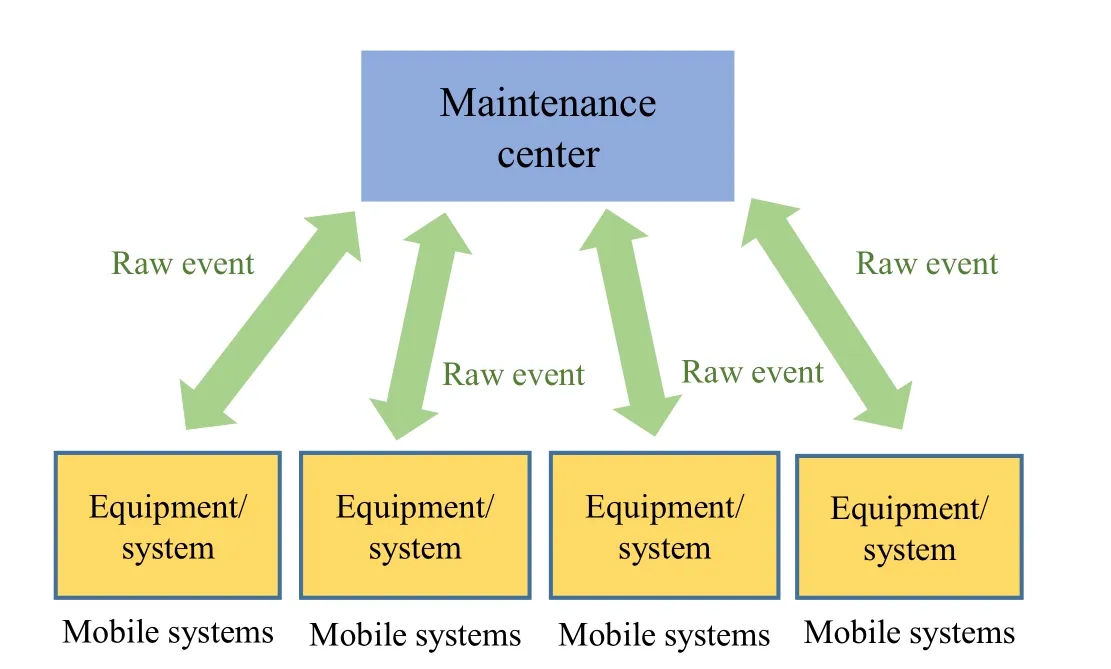
Fig. 2 Centralized fleet EMADM
Advantages The advantages of this kind of architecture concern its ease of deployment, its ability to facilitate the collection and storage of data, and its easy adaption to the requirements introduced for low-complexity embedded systems. It also offers powerful data analytics solutions,including big data processing to facilitate the monitoring and diagnosis functions of the whole fleet. Finally, it is compatible with modern technological solutions (cloud technology, Internet of things, etc.).
Drawbacks One drawback concerns some limitations in terms of reliability and diagnostic accuracy because the context and the physical environment of the mobile systems are rarely taken into account. Another issue is the difficulty of controlling the amount of time that may be required to process data and generate advice and knowledge for the MC. Moreover, data acquisition is not systematically in real time and depends on several external factors (transmission network quality, local data memorization capacity, etc.). Lastly, these architectures are relatively inflexible, as the configuration of the systems (and fleet) monitored often requires long-term stability. The question of modifying equipment or inserting new systems is rarely addressed as software reprograming may require a significant amount of time.
2.3.2 Edge-centralized fleet EMADM
This kind of architecture is characterized by the introduction of intermediate ‘‘fog node networks’’ for calculation and communication. This is achieved using recent technology called‘‘edge computing’’that fosters the creation of an intermediary level between mobile systems and the MC.Edge computing pushes computing applications, services,functions, and data from centralized cloud computing centers or constrained devices to distributed nodes at the edge of networks to achieve higher application performance and a better experience [16]. Thus, diagnosis and monitoring functions benefit from off-loading computation,storage, and acceleration to such fog nodes through internode communication and resource sharing [16]. Figure 3 illustrates this type of architecture that can be seen as an evolution of the centralized EMADM.
Some recent technologies are pushing this relatively new kind of architecture. There are a few applications in the service sector,for example,including AWS Lambda@Edge,1https://docs.aws.amazon.com/lambda/latest/dg/lambda-edge.html.Microsoft Azure IoT Edge,2https://azure.microsoft.com/en-us/services/iot-edge/.EdgeConneX,3www.edgeconnex.com.and Equinix.4www.equinix.com.These applications can support any mobile or fixed system such as drones and software applications using Internet of things and augmented reality. However,there are currently no applications in the transportation sector.
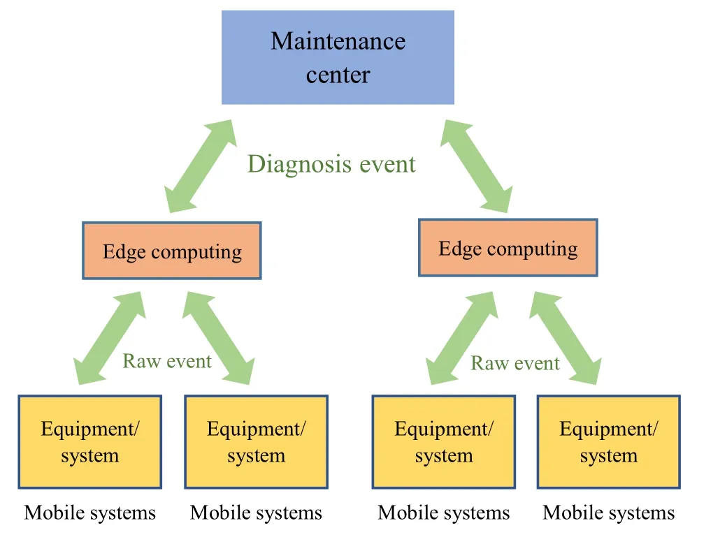
Fig. 3 Edge-centralized fleet EMADM
Advantages The advantages of this kind of architecture include its ability to limit and control the transmission of large volumes of data and events to the ground MC. It is also compatible with modern technological solutions and enables the integration of a basic level of modularity through the decoupling of functions and algorithms.
Drawbacks Transposed to the transportation sector, the drawbacks may be the same as those identified for the centralized type, except regarding modularity.
2.3.3 Decentralized fleet EMADM
Figure 4 schematizes this kind of architecture where the onboard diagnosis units operate independently. They do not communicate with each other, and they only use the limited observations of their subsystems. Monitoring and diagnosis results are transmitted to the ground MC [17].
Illustrative examples can be found in the air transport sector with the Central Maintenance System (CMS) [18]and a decentralized architecture for diagnosis in road vehicles [19], as well as in the maritime sector with the Extensible CBM Architecture for Naval Fleet Maintenance Using Open Standards [20].
Advantages The advantages of this kind of architecture include its ability to limit and control the transmission of large volumes of data and events to the ground MC. Realtime contextualized diagnosis is also possible. In addition,it gains from the greater precision, modularity, and diagnosis capabilities of complex systems composed of subsystems.
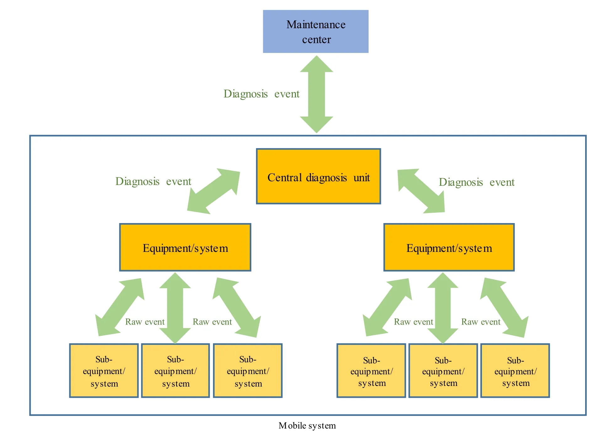
Fig. 4 Decentralized fleet EMADM
Drawbacks Such architectures rarely meet requirements in terms of modularity and can make false diagnoses when there is interference between subsystems.
2.3.4 Decentralized and cooperative fleet EMADM
This kind of architecture goes a step further,enabling units of the same level to cooperate and thus obtain additional information to enrich their local observations and provide a more robust diagnosis [21]. The exchanges imply additional information flows onboard the mobile system,which thus requires more powerful local computing functions(e.g., a control unit with processors and memory) [22].Figure 5 schematizes this type of architecture.
Examples include an architecture for monitoring a transport system proposed in [23] and the VIPR (vehicle integrated prognostic reasoner) architecture for monitoring aerospace vehicles proposed in [24]. Another example is the EMH (embedded monitoring holarchy) architecture proposed in [5], where the holonic paradigm is used to organize the architecture in which units are holons integrating both the physical part of the monitored system and its monitoring unit. The fundamental assumption for a holon is that it is a whole systematically composed of a physical and an informational part. This approach also allows for recursion of the monitoring processes (a holon being composed of smaller, more localized holons monitoring smaller components). At each level of the holonic decomposition of the mobile system,a holon is created for each system that is subject to monitoring and diagnosis functions.
Advantages This architecture inherits from the advantages of decentralized fleet EMADM, but thanks to horizontal cooperation between equipment of the same level,knowledge constructed from big data is potentially more robust.
Drawbacks Despite the fact that this kind of architecture is widely suggested in the domain of manufacturing control, there is a clear lack of development in the transportation sector. Methodological support tools as well as generic design approaches thus are missing.
2.4 Motivations of the work
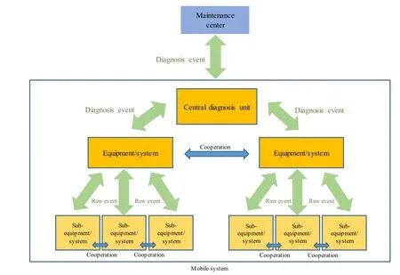
Fig. 5 Decentralized and cooperative fleet EMADM
The literature review has shown that none of the existing types of fleet EMADM provides a comprehensive solution to all the issues introduced previously. We believe that an effective fleet EMADM developed using a standardized modeling of events coupled with a cooperative, hierarchized management process of these events, from monitoring raw data of a component to high-level knowledge at fleet level, can become the backbone of the fleet CBM system. The remainder of this paper presents this fleet EMADM called EMH2.
3 EMH2
EMH2is based on the decentralized and cooperative type and generalizes the use of holonic principles previously proposed in the EMH architecture, typically the recursive decomposition of cooperative holons. Some principles inherited from the edge-centralized EMADM are also integrated for deployment aspects. The definition of generic event modeling is another key element of the contribution. EMH2has been designed to be applicable to any kind of system or equipment up to fleet level.
Hereinafter,the main theoretical points of the EMH2are presented, bearing in mind that tests on some potentially usable technological solutions have been conducted and presented in[1].This presentation starts with the SurfEvent model,as it constitutes the foundation of the holons and the architecture.
3.1 SurfEvent model
In EMH2, every event is modeled and handled using a single model. One key idea is to model and manage every event in the same way thus rendering our approach more generic. For example, with this approach, expert rules can be designed independently of the monitoring domain and the real-time diagnostic processing performance, thus contributing to the specification related to modularity.This generic model of an event is called a ‘‘SurfEvent.’’ Every event entering or traveling within the EMH2is a ‘‘SurfEvent.’’ Interoperability of SurfEvents with other information systems must then be addressed but this is not within the scope of this paper.
A SurfEvent is modeled as a set of the following parameters:
· A unique identification (its name).
· Two possible data types: quantitative(e.g., the average time for the pantograph of a train to connect or the average duration of a door access opening cycle on a train) or qualitative (e.g., the global health status of a train door system described as normal, degraded,critical, etc.).
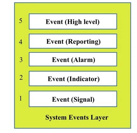
Fig. 6 Description of the SurfEvent abstraction layers(inspired from ISO 13374)
· A level identifier can be modified according to the abstraction layer to which it corresponds. These levels of abstraction taken from ISO 13374 are structured from low level to high level and are called signal,indicator, alarm, reporting, and high level, respectively[25-27] (see Fig. 6).
· Two possible statuses: The first is called ‘‘testing and development’’ when it is used by engineers during a teaching process for a specific holon,and the second is called ‘‘production’’ when it is generated by a mobile system during use.
· Two possible origins: ‘‘calculated’’ (generated from other events) or ‘‘original’’ (obtained directly using sensors).
· A unique source called ‘‘emitter.’’ An emitter is associated with the hierarchical structure of every mobile system.
All these parameters defining a SurfEvent can be modeled using an Entity-Relationship (ER) Unified Modeling Language (UML) diagram [28]. Figure 7 describes such a model.
The generic model of a SurfEvent, which takes into account the different types, status, and different locations(emitter) of SurfEvents and their related contexts, is provided in Fig. 8. In our work, the generic model of a SurfEvent is considered as a way of formalizing holon knowledge. This approach also enables the monitoring processes to be independent of the target systems and enables the development of applications that are optimized in terms of memory usage.

Fig. 7 SurfEvent UML model

Fig. 8 Generic model of a SurfEvent
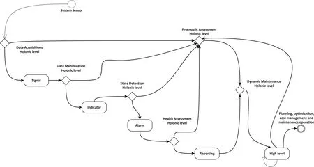
Fig. 9 Model of a SurfEvent life cycle
The creation, handling, and destruction of a SurfEvent are called‘‘the life cycle of a SurfEvent’’throughout which some of its parameters may be modified. Its identifier, for example,can evolve when the SurfEvent crosses the entire EMH2architecture, from a low-level sensor to reach the maintenance operator. This original approach facilitates tracking of SurfEvents and relevant activities from when they enter the EMH2to when they leave.A model of such a life cycle is proposed in Fig. 9 using a state diagram formalism.
3.2 Holonic architecture
To design the holonic architecture, the first development consisted in adapting the ISO 13374 layers by removing the advisory generation (AG) layer (initially intended to generate advice in an isolated system)and replacing it with a new one called ‘‘dynamic maintenance.’’ Within a system, the AG layer elaborates a monitoring report from the diagnostic and prognostic functions and assists the maintenance operators in their choice of maintenance action.Dynamic maintenance is a specific holonic level that aims to generate advice based on fleet level mobile system diagnostic and prognostic functions, optimize the availability of each piece of mobile equipment, and reduce the impact of maintenance on operating costs, cf. Fig. 10.These layers (data acquisition, data manipulation, state detection, health assessment, prognostic assessment, and dynamic maintenance) comprise the basic structure of the EMH2holonic architecture(a holonic level for each layer).The experience gained with the EMH architecture showed us that this is an interesting approach for handling big data and for enabling cost optimization of fleet maintenance.AG has also been integrated into each holonic level to enable holons of a given level to elaborate their own advice and recommendations and send them to higher holonic levels. This also offers the opportunity to elaborate a distributed deployment of the holonic levels.
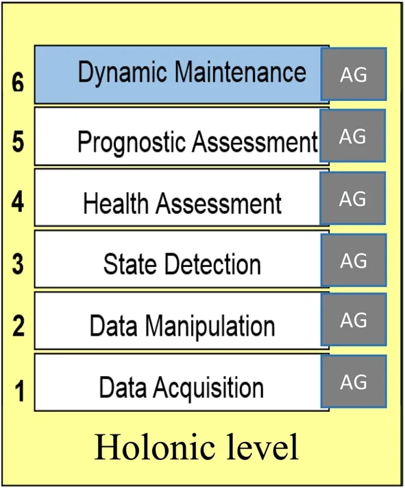
Fig. 10 Holonic level dynamic maintenance
A holonic level refers to a group of holons belonging to the same family. These holons thus inherit the mission of the layer they represent. This approach offers huge advantages in terms of automated deployment. In EMH2,each holonic level handles the system and subsystem monitoring and diagnosis for the level through a set of holons.
A holonic level is modeled as a set of the following elements:
· A set of holons grouped by family of equipment.
· An interface module for inter- and intra-connection of the different components of the holonic level.
· A workflow management system [29] looks out for events from sensors and/or other holonic levels. When an event arrives, the system identifies its origin (the sending system) and triggers the corresponding holons in charge of supporting it. Figure 11 schematizes the layout of all the holonic levels in EMH2.
3.3 Holon design
In EMH2, holons are designed to embed a monitoring and diagnosis function (according to the mission of each holonic level), as in the EMH architecture, but each holon now contains an expert system [30] and several interfaces dedicated to cooperation, knowledge, and information exchange with other holons and systems. A key aspect is that these holons are designed to enable the integration of any off-the-shelf monitoring and diagnosis models as long as they can discriminate between normal and abnormal behaviors and that they can be adapted to handle SurfEvents. The holon monitoring and diagnosis function is called ‘‘SurfProcessing’’ and is implemented using an expert system. This approach offers the ability to reason under uncertainty and to explain the solutions given to maintenance operators using backtracking processes. This expert system is composed of a knowledge base and an inference engine [31, 32]:
· The proposed holon knowledge base is based on a context-free grammar.The choice of this grammar[31]has been the subject of a comparative study not described in this paper. A type-2 grammar has been selected to allow us to generate the mathematical,logical, textual, and temporal expressions associated with the field (calculate) of a SurfEvent. As with a SurfEvent, knowledge can be in ‘‘test mode’’ (using a simulator, for example) or in ‘‘production mode’’(validated and currently in use).
· The proposed holon inference engine is based on a pushdown automaton [31] to allow context-free grammar recognition.The choice of this automaton has been the subject of a comparative study not described in this paper.The inference engine uses backward chaining, and the reasoning mode of SurfEvents is either cycle-based or state-based:
· Cycle-based reasoning mode: A cycle is defined by its start and its end conditions. Each condition is a set of SurfEvents. Its calculation depends heavily on the physical characteristics of the target system. A cycle has the following characteristics:
· All SurfEvents within the cycle are unique.
· A cycle has a start date and an end date.
· The duration of a cycle is variable.
For example, when a train door opens, a door-opening cycle and a door-closing cycle are distinguished and each cycle has its own start and end conditions. The main advantage of cycle-based reasoning is reactivity because if one waits for the arrival of all the SurfEvents before launching the reasoning process of the expert system, then precious time may be lost. A formal description is as follows:
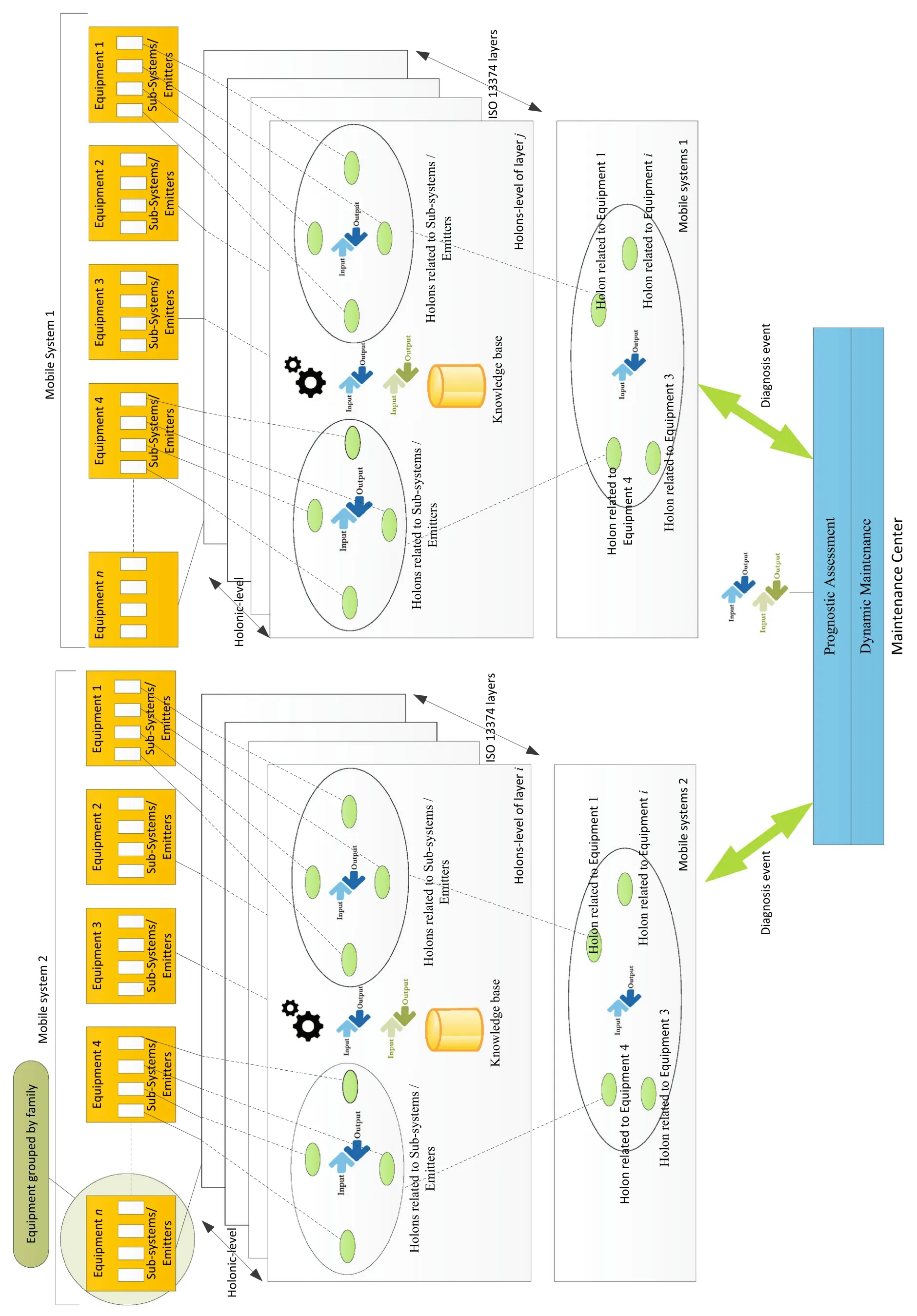
Fig. 11 Layout of the holonic levels in EMH2

where s is a system composed of a set of subsystems and components, cycle(s) represents the cycle of the system s,e1and e2are sets of events that represent the start and end conditions of a cycle, respectively, such that each SurfEvent in a set (e) is unique; I(e1,t) is the start condition evaluation of the cycle; I(e2,t) is the end condition evaluation of the cycle; SurfEventiis the occurrence of a SurfEvent in a start or end condition.
· State-based reasoning mode: In this mode, reasoning processes start when a change in the value of each SurfEvent is observed. For SurfEvents that are not observed, their last observed values are retained. The advantage of this mode is that no knowledge about the system to be monitored is necessary. However, continuous monitoring and a memory device are required.A typical example of a physical piece of equipment concerned by this mode is a lamp (switched on/off). A formal description of this reasoning is as follows:

where SurfEventtis the change in state of a SurfEvent at a given time t and state(s,t)represents the state of the system s at the time t.
Backward chaining is used for these two modes (cyclebased or state-based):
· When a SurfEvent occurs, the expert system considers it as a fact.All the rules of the knowledge base where this SurfEvent is identified are selected.
· The execution order of the selected rules is established according to their abstraction level.The signal level is of the highest priority, followed by the indicator level, and so on.
· For a given abstraction level, an order of execution of the rules is established starting with simple rules and finishing with complex ones.A rule is said to be‘‘simple’’ when its evaluation does not require any cooperation or exchange with other holons or any heterogeneous system; otherwise, it is called‘‘complex.’’
· A rule is executed in either cycle- or state-based mode.
· The result serves as a fact for the other rules.
· If the expert system cannot explain a fact,the holon inference engine requests an explanation from a specific module in charge of learning, named adaptation module (not described in this paper).
Figure 12 illustrates the algorithmic description of the backward chaining process using flowcharts. The ‘‘adaptation’’ and the ‘‘update knowledge’’ modules, which deal with holon learning abilities, are not described in this paper.
4 Deployment process and methodological aspects
The EMH2architecture is designed to facilitate asynchronous and progressive deployments. We, therefore,adopted the edge computing paradigm and equipped the EMH2architecture with different edge computing nodes.The principles are as follows:
· For mobile systems Iterative deployment of the different holonic levels for each layer (data acquisition, then data manipulation, then state detection, etc.) can be achieved progressively and specifically depending on the mobile systems chosen and the equipment to be monitored. In addition, within a single holonic level,the progressive implementation and localization of hardware can be defined for every holon according to the constraints of embedded system calculators (available memory space, computing power, communication bandwidth, etc.).
· For intermediary edge computing (EC) nodes Progressive deployment of EC nodes can limit the transmission of large volumes of data and events from mobile systems through the implementation of data acquisition,data manipulation, state detection, and health assessment holonic levels at intermediary nodes between the mobile system and the MC. These nodes can be deployed according to criteria expressed by fleet operators, for example by building facility, by region,or by country.
· For the MC Whatever the state of the progressive implementation, mobile systems that are not connected to EC nodes will be directly connected to the MC.
An example of this progressive deployment of the EMH2within four mobile systems at a given moment is illustrated in Fig. 13. In this figure, four mobile systems have different levels of implementation of holonic levels for their systems (equipment). For mobile system 2, three holonic levels are already implemented for system 1,while only one (data acquisition) is implemented for system 2.
Increasing the security of exchanges between mobile systems, the holons, and the wayside MC to fight cybercrime [32] is a major issue during deployment. Therefore,it is assumed that to deploy any EMH2,each mobile system must have a certificate signed by the wayside MC to allow it to communicate with other systems.The standard public key infrastructure (PKI) [33] can be used, for example.
This ensures basic data authenticity, confidentiality,integrity, and availability. The PKI was chosen with respect to symmetric and asymmetric cryptography [34]because it associates the physical identity of a mobile system such as its identity, geographical location, or operator with a digital fingerprint consisting of a key pair.It then provides a strong mechanism for authentication,revocation, storage, and key sharing managed by a trusted third-party certification authority.
In EMH2,this technology provides mobile systems with a key pair, which is detailed as follows:
· A public key, known by all the mobile systems and heterogeneous systems, used to encrypt and decrypt SurfEvents during exchanges between the mobile systems and the MC.
· A private key,known by the unique mobile system that holds it, used to encrypt, decrypt, and authenticate the signature of its mobile system.
For example,a mobile system encrypts the diagnostic data it sends to the maintenance center using the public key of the latter to ensure integrity and confidentiality.Therefore,only the MC can decrypt the data sent using its private key.
5 A case study: a real application of the proposed method to a fleet of trains
This section presents a case study that corresponds to a real-world application of the proposed EMH2to a fleet of ten trains currently in use, in collaboration with our industrial partner, Bombardier Transport.
To evaluate the effectiveness of the EMADM designed,three key performance indicators translating the cost,quality, and time dimensions (see introduction) were identified:
· KPI#1 Number of fleet maintenance visits (corrective,preventive, and unplanned) per week. This indicator is a measure of the maintenance costs generated using a given EMADM.
· KPI#2 Time needed by a maintenance operator to investigate and diagnose,and then generate reports and follow-ups relating to a maintenance operation. This KPI translates the quality of the diagnostic processes and the rapidity of the operation using the given EMADM.
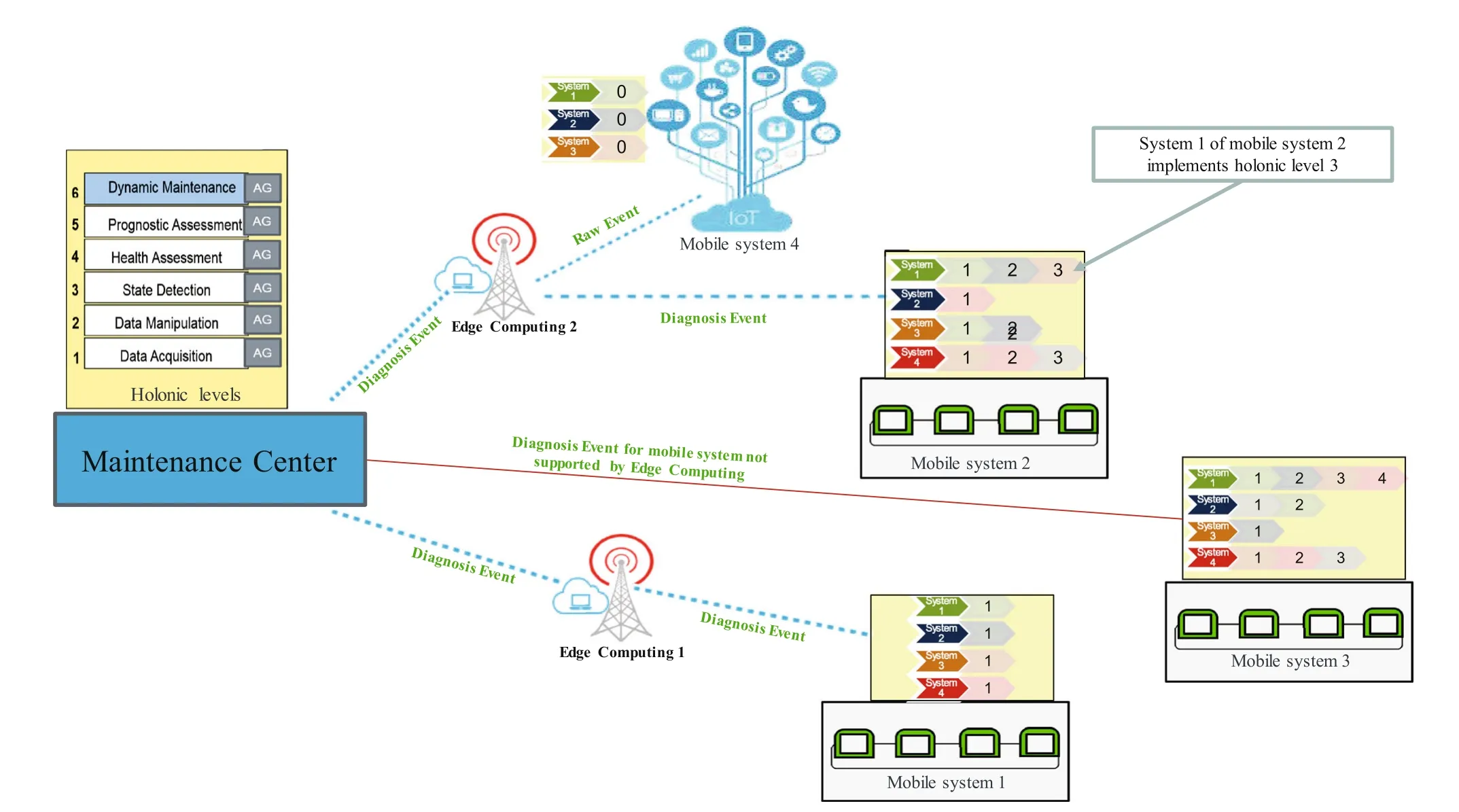
Fig. 13 Progressive deployment of the EMH2 architecture

Table 1 Current situation for each KPI
· KPI#3 Time needed by the given EMADM to update data regarding the health status and monitoring of a train.This indicator translates the reactivity of the event management architecture when events occur.
Current exact values for these KPI are confidential but orders of magnitude can be provided and are indicated in Table 1. These indicators concern our industrial partner’s current event management organization to be improved using the proposed EMH2.
The industrial partner has set the KPI objectives as described in Table 2.
The application has been developed in C# using the Microsoft Asp.Net Core platform integrating different solutions such as SQL Relational,No SQL,and time series database (TSDB). This application uses microservices to implement data acquisition, data manipulation, state detection,and health assessment holonic levels.The whole application is compliant with modified standard ISO13374. The microservice approach aims to design a single solution as a series of small services where each service is a module that supports a specific need as well as its own execution and communication process. A microservice is easy to define and implement thanks to the use of lightweight mechanisms such as representational state transfer(REST), message queue (MQ), and WebSocket [35]. A microservice approach then offers huge advantages for real-time monitoring, flexibility, modularity, automated deployment, scalability, and performance. This allows the designer to overcome the limitations of other approaches such as service orientation [36, 37].

Table 2 Target for each KPI
5.1 Experimental study
Prior to deployment, several experiments were conducted with human experts to establish the knowledge base of the different holons for each level,to evaluate the relationships between SurfEvents, and to adapt this knowledge according to the real systems.Human experts were interviewed to establish holon knowledge.It took 2-3 weeks to extract the knowledge from four experts (system engineers). Simulations were then conducted to validate the knowledge extracted. Due to reasons of confidentiality, it is not possible to provide more details about the experiments and the application,especially the algorithms. However,Figure 14 provides a formal sample of a holon knowledge base using the type-2 grammar.
As detailed in Fig. 14, a ‘‘Puissance’’ SurfEvent at‘‘indicator’’level is calculated from the difference between the SurfEvent ‘‘TAirTraiteCalc[degC]’’ and ‘‘TAirMelange[degC].’’ Both are ‘‘signals’’ generated directly by sensors or transducers. This ‘‘puissance’’ SurfEvent triggers an active alarm‘‘Detect_seuil’’at‘‘alarm’’level when its value exceeds the threshold ‘‘10’’ [degC]. A SurfEvent‘‘Puissance_Alarme’’ at ‘‘reporting’’ level is triggered if‘‘Detect_seuil’’ has been triggered more than three times over the previous 24 h (‘‘One_Day’’). The SurfEvent‘‘Puissance_Alarme’’ can then be combined or not with other SurfEvents of the same or lower levels in order to determine health conditions or future failure modes that will be used to plan maintenance operations.
5.2 Teaching the team in charge of maintenance operations
Training sessions have been organized to facilitate the appropriation of the EMH2solution implemented by the team in charge of maintenance operations.In order to help them and to avoid any manipulation errors, a troubleshooting help tool was designed in collaboration with the team.This tool is connected directly to the MC.During an inspection or a repair operation,the maintenance officer physically connects this tool to the train network.With this tool, he can communicate directly with a piece of equipment on a train or a subsystem, as well as investigate and carry out orders. Figure 15 presents the user interface of the tool.
For example, during an inspection and repair operation on hvac1 (IP address: 10.0.072) on train z5500659 (see Fig. 15), the maintenance officer first chooses the type of network (ip or mvb) and the vehicle number (v11) so that he can launch an investigative session on this material and gather relevant SurfEvents.
5.3 Assessment of the results obtained and comparison with targets
The experiment was conducted in 2016. After several weeks of use,the industrial partner was able to evaluate the real impact of the EMH2architecture on the KPI introduced previously.
Table 3 presents the results obtained for each KPI.
Some comments from experimental feedback regarding the performance of the EMH2architecture are presented hereinafter:
· KPI#1 The entire life cycle of a SurfEvent is effectively under control, from its generation to the final maintenance tasks. A detailed calculation of this KPI over several weeks(sliding mode)is provided in Fig. 16.As one can see,the maximum number of visits(eight)was only encountered once. Generally, only one visit was conducted per week.
· KPI#2 Today, thanks to the troubleshooting assistance tool, all the tasks are automated. This explains the decrease in the average duration of interventions to less than 20 min, which is mainly due to the direct control mechanisms of the systems concerned and sharing experience feedback from the entire fleet.

Fig. 14 Formal sample of the holon knowledge base using the type-2 grammar (surfeventcount: A function that counts the number of occurrences of a SurfEvent between two dates. BackToDate: A function that returns the time period between two dates. Iif(Exp, TruePart,FalsePart): A function that returns either TruePart or FalsePart, depending on the evaluation of the Boolean Expression Exp)
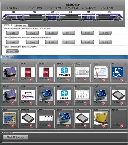
Fig. 15 Troubleshooting help tool: user interface

Table 3 Results achieved
· KPI#3 Up to now,the reactivity cycle has been reduced to 2 h.This is due to the ability of the EMH2architecture to control the reactivity of the entire maintenance chain,that is to say, the supervision, diagnosis, planning, and optimization phases of maintenance operations.
5.4 Global discussion about the case study
The system engineers quickly adapt to the EMH2architecture. The modularity and the reactivity of the architecture facilitated the continuous monitoring of the fleet of trains and knowledge could easily be added to specific holons. The existing state of knowledge is being assessed through long-term experimental feedback.
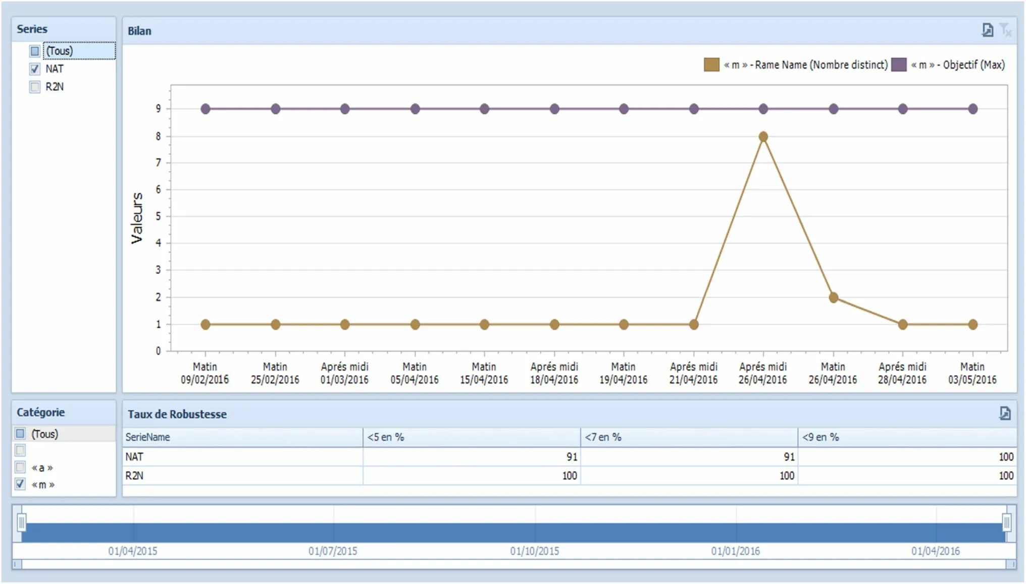
Fig. 16 Evolution of KPI#1 over several weeks
From first short-term feedbacks relating to this case study elaborated by users (maintenance operators), the EMH2architecture was able to speed up, facilitate, digitalize, and automate the diagnosis and monitoring processes of various kinds of equipment inside a train and was able to address fleet level. Moreover, following this comprehensive, long application, the partners are convinced that the EMH2can be applied to other modes of transportation and industrial fields, typically nuclear plants,manufacturing systems, or intelligent buildings.
The impact of the EMH2architecture on the industrial organization is de facto quite substantial, and thus, correct handling of this issue is critical for success. For example,the EMH2architecture can asynchronously generate highlevel CBM SurfEvents detailing scheduling, inspection,control, overhaul, and repair operations to be carried out.This high responsiveness of the proposed architecture is a new feature to be added to corrective maintenance methods already used by maintenance operators.However,this may destabilize conventional operational maintenance processes, so to support this increased reactivity, a profound adaptation of the team in charge of maintenance operations is necessary. This adaptation involves understanding the connected technologies inside the mobile systems and all the holonic level implementations of the EMH2architecture.The objectives are to provide the maintenance officer with the ability to communicate directly with the systems and subsystems of a mobile system,to investigate,and to execute commands in order to optimize maintenance operations and handle the maximum number of tasks possible and, therefore, be as reactive as possible when interacting with the EMH2architecture. Specific tools combining troubleshooting help tools and user guides using augmented reality and voice recognition to limit the need to access remote data and knowledge, as well as to facilitate maintenance activities, for example, must be designed for this purpose.
Two limitations of our contribution have been identified from these experiments:
· First, during the experiment, we encountered a lack of efficiency of the adaptation process that leads to new accurate knowledge regarding a newly integrated piece of equipment and the ability of the event management architecture to integrate this new knowledge. For example, changing a door requires the knowledge of its monitoring holon to be updated. An adaptation module is under development to solve this kind of issue and generate the relevant knowledge automatically.
· Second,despite the fact that for this case study the KPI improved,the complete validation and the optimization of the EMH2remain to be done through simulations,for example,with the integration of prognosis and dynamic maintenance holonic levels to assess the performance of a global and dynamic fleet level maintenance strategy. Indeed, a single case study is insufficient to draw conclusions as to the effectiveness of the EMH2for any kind of train fleet.
6 Conclusion and future research
The aim of this paper was to present a novel kind of event management architecture, called EMH2, aimed at facilitating the diagnosis and monitoring of a fleet of mobile systems and its application through a sound case study.This architecture exploits holonic principles, from lowlevel sensors to the entire mobile system.It generalizes the EMH architecture in two ways: (1) It is applicable to any kind of system or equipment, and (2) it addresses fleet level. This architecture relies on the concept of a unified event model,called SurfEvent.EMH2has been applied to a fleet of ten trains in collaboration with our industrial partner. The results from the case study encourage us to pursue our work and to seek other applications in various industrial fields.
AcknowledgementsThe work presented in this paper was led within the context of a research project whose partners were Bombardier Transport, the Polytechnic University of Hauts-de-France (UPHF)and the French National Center for Scientific Research (CNRS). It was also led with the financial support of the Chadian National Centre for Research (CNRD).
Open AccessThis article is distributed under the terms of the Creative Commons Attribution 4.0 International License (http://creativecommons.org/licenses/by/4.0/), which permits unrestricted use,distribution,and reproduction in any medium,provided you give appropriate credit to the original author(s) and the source, provide a link to the Creative Commons license, and indicate if changes were made.
 Railway Engineering Science2019年3期
- Railway Engineering Science的其它文章
- Correction to: Can a polycentric structure affect travel behaviour? A comparison of Melbourne, Australia and Riyadh,Saudi Arabia
- Using Kalman filter algorithm for short-term traffic flow prediction in a connected vehicle environment
- A fault prediction method for catenary of high-speed rails based on meteorological conditions
- Statistical delay distribution analysis on high-speed railway trains
- Speed profile optimization of catenary-free electric trains with lithium-ion batteries
