Mathematical analyses of the GPS receiver interference tolerance and mean time to loss lock
Ehab M. Shaheen, Sherif A. Elgamel
Electronic Warfare Department, Military Technical College, Kobry Elkoba, Cairo, Egypt
A B S T R A C T In this paper, novel mathematical expressions are derived for the Global Positioning System (GPS)receiver interference tolerance in the presence of different types of interference signals such as:continuous wave interference, narrowband interference, partial band interference, broadband interference, match spectrum interference and pulse interference.Also, in this paper the mean time to loss lock is determined in order to analyse the mentioned interferences effect on the GPS receiver. These derived analytical expressions are validated with the aid of extensive simulation experiments.
1. Introduction
The device which provides users with accurate navigation and timing services worldwide is well known as the Global Positioning System (GPS). It has become the navigation and timing system of choice for many users due to its accuracy,ubiquity and low cost[1].
Today, modestly priced differential GPS systems can provide centimetre level of accuracy. Thus, the outstanding challenge for GPS receiver designers and users is not increasing accuracy but enhancing robustness. As such, the threat to GPS robustness presented by wideband radio frequency interference(RFI)or jamming has attracted a significant amount of current attention [2].
The performance of a GPS receiver usually depends on the tracking loop, which enables continually the generation of the carrier frequency and the code replicas that achieve maximum correlation in the GPS receiver [3]. Only reliable code and carrier signal tracking allows a GPS receiver to estimate the pseudo ranges and to extract the navigation data.In the case that the tacking loop unable to track the incoming GPS satellite signal, the position cannot be calculated [4].
The tracking loops can be considered as the heart of the GPS receivers. It had proven that the carrier tracking loop was more sensitive to noise and interference than the code tracking loop[5].Therefore,the carrier tracking loop phase jitter and carrier to noise ratio threshold can be used to investigate the GPS receiver performance in the presence of interference.
The interference effect on the tracking loops had already been addressed by many researchers. In Ref. [6] the interference thresholds for the GPS receiver was obtained by the navigation laboratory test without any analytical analysis.The performance of the tracking loop under interference and dynamic effect was assessed by using software GPS receiver without analytical analysis as presented in Ref.[7].In Ref.[8]the continuous wave interference(CWI)effect on the tracking performance of the GPS receivers was investigated without considering many parameters such as the carrier to noise ratio threshold, the GPS receiver interference tolerance, and the mean time to loss lock(MTLL).
To this end; the main objectives of this paper can be summarized as follows:
· Closed form analytical expressions for the carrier tracking loop phase error are derived in the presence of different types of interference signals such as: CWI, narrowband interference(NBI), partial band interference (PBI), broadband interference(BBI),match spectrum interference(MSI)and pulse interference(PUI) which are previously classified in Ref. [9].
· Novel mathematical expressions were derived for the GPS receiver interference tolerance in the presence of the previously mentioned interference types.
· Also, in this paper the mean time to loss lock is determined in order to analyse the interference effect on the GPS receiver.
· The derived analytical expressions were validated with the aid of extensive simulation experiments.
This paper is organized as follows.The interference effect on the carrier tracking loop is measured by investigating the tracking loop phase jitter in section (2). In section (3), a novel mathematical expression for the GPS receiver interference tolerance is derived and the MTLL value is defined. A set of analytical and simulation results for different interference and GPS tracking loop parameters are presented in section (4). Section (5) concludes the paper.
2. Interference effect on the carrier tracking loop phase jitter
Once comparing the carrier tracking loop with the code tracking loop, it is noted that the carrier wavelength is much shorter than the code chip length. It is also noted that the carrier tracking loop needs to track all the dynamics while the code tracking loop needs only to track the dynamic difference between the carrier tracking loop and the code tracking loop when carrier aiding is applied to the code tracking loop[5].Therefore,one can expect that the carrier tracking loop is more sensitive to noise and interference than the code tracking loop.Thus,the carrier tracking loop can be used as a measure to investigate the GPS receiver performance in presence of different interference signals which affect the carrier tracking loop.This can be measured by estimating the tracking loop phase jitter.
The carrier tracking loop phase jitter,σpllfrom all uncorrelated phase error sources can be written as [4].

where σtpis the thermal noise phase jitter, σvis the vibrationinduced oscillator jitter in degrees, σAis the Allan deviationinduced oscillator jitter, and θeis the dynamic stress error.
The thermal noise phase jitter σtpcan be written as [4].

where Bnis the loop noise bandwidth [Hz], C/Nois the postcorrelation carrier to noise density ratio, and Tdis the correlator coherent integration time.
For a stationary or slowly moving receiver, it is fair to assume that the effect of dynamic stress can be negligible and the oscillator phase noise is small and transient [6]. Without loss of generality,the other sources of phase jittering can be neglected and the thermal noise is considered as the only source for phase jittering.
Thus, the carrier tracking loop phase jitter, σpllcan be considered to be equal to the thermal noise jitter, σtpand it can be written as

Fig.1,depicts the phase jitter value for the carrier tracking loop at different values of the coherent integration time, Tdand noise bandwidth.
It is shown that the carrier tracking loop phase jitter is strictly dependent on the noise bandwidth Bn, and the integration time Td.In order to increase the performance of the carrier tracking loop in the absence of interference,the coherent integration time can be increased or the carrier tracking loop noise bandwidth can be decreased.
To simplify the evaluation of the tracking loop in the presence of interference, the following will be assumed:
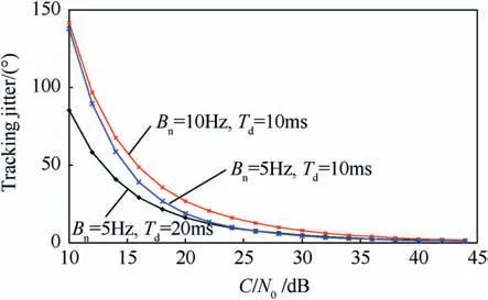
Fig.1. The carrier tracking jitter vs. C/No.
1 The replica reference code is perfectly aligned with the satellite code, τn=τs= 0.
2 The phase error Δθsis relatively constant over the integration period, Td.
The interference signal raises the noise power density in the correlator output causing a drop in the C/Novalue. In Ref. [10], the post-correlation C/Nofor the GPS L1 C/A code signal in the presence of CWI, NBI, PBI, BBI, MSI or PUI were analytically derived. Modifications can be done to the derived formulas in order to analyse the GPS receiver carrier tracking loop performances in the presence of different interference signals.
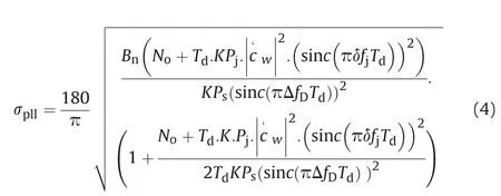
Substituting into the carrier tracking phase jitter presented in Equation (3), when the code phase estimation error Δτ = 0; the tracking phase jitter in the presence of CWI can be derived as where Psand Pjare the GPS signal and the interference power at the correlator input respectively,ΔfDis the carrier frequency estimation error,the interference frequency error Δfjis the difference between the interference frequency fjand the receiver reference carrier frequency (Δfj= fj- ˆfD), δfjis the difference between fjand the nearest C/A code spectral line (number w), the non-coherent integration time K=1, and |c′w| is the amplitude of the C/A code Fourier series coefficient number w.
For the evaluation of the derived mathematical expression for the tracking phase jitter in presence of CWI;a comparison with the results presented in Ref. [8] will be achieved.
The tracking phase jitter in the presence of CWI can be written as [8]: (see (5))
In Ref. [8], the GPS C/A code PRN6 was used, where the worst line component is at 227 kHz frequency with respect to centre frequency.
A comparison between the carrier tracking loop phase jitter in the presence of CWI signal using Equation (4) and the results presented in Ref. [8] is depicted in Fig. 2a and Fig. 2b when the integration time is equal to 5 ms and 20 ms respectively.In the case that the interference frequency is varying from 255 to 299 kHz,the interference-to-signal power ratio Pj/Ps= 8 dB, and the noise bandwidth of the carrier tracking loop Bn=20 Hz It is concluding that, both the (7) and (4)yield the same results. (see (6))
In Ref. [8], the impact of CWI was only investigated. Due to the good match between the derived formula and that presented in Ref. [8];following the same procedure,the tracking phase jitter in the presence of different types of interference signals can be derived as follows.
The tracking phase jitter in the presence of NBI is formulated as(6).The tracking phase jitter in the presence of PBI is founded to be:(see (7))
The tracking phase jitter in the presence of BBI is formulated as(see (8) and (9)):

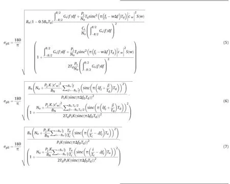

The tracking phase jitter in the presence of MSI is formulated as(see (10)):
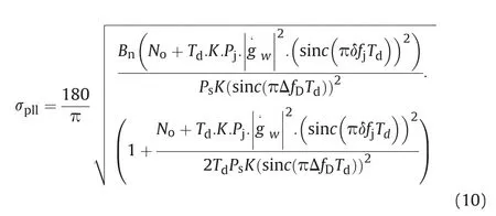
The tracking phase jitter in the presence of PUI is formulated as(10).
In Fig. 3a, the carrier phase jitter (CPJ) in the presence of CWI signal versus the interference frequency error is depicted for interference-to-signal power ratio Pj/Ps= 20 dB, and the noise bandwidth of the carrier tracking loop Bn=5 Hz.This is done for different integration time values 1, 5 and 20 ms.
It has been seen that the CWI can affect the carrier loop if its frequency is close to the C/A spectral line.Increasing the integration time,will increase the carrier tracking loop error.It is also seen that the attenuation of the carrier tracking loop performance has similar characteristics as obtained for the C/No.
Fig. 3b shows the CPJ in the presence of NBI signal with bandwidth 400 Hz, when the Pj/Ps=20 dB and the coherent integration equals to 20 ms. The noise bandwidth of the carrier tracking loops takes two values Bn=5 and 10 Hz.It is clear that,the CPJ in the presence of NBI is less than CPJ in the presence of CWI. When the Bnvalue is increased,the carrier tracking loop phase error will increase too.
Fig. 3c indicates the CPJ in the presence of PBI signal with bandwidth BN= 40 kHz, the interference frequency error is varying from 0 to 2 MHz, Pj/Pstakes two values 20 and 30 dB and Td= 20 ms. It can be seen that the PBI cause small jitter on the carrier tracking loop in comparison with the CWI or NBI, and its effect decreases by increasing the interference frequency error.
The CPJ in the presence of BBI signal is shown in Fig.4a,for the Pj/Ps= 20 dB, and the noise bandwidth of the carrier tracking loops Bn=5 Hz.This is done when Td=20 ms.It is shown that the effect of the BBI on the carrier loop decreases by increasing the BBI bandwidth.
In Fig. 4b, the CPJ in the presence of MSI is depicted when the Pj/Ps= 20 dB.for different integration time values 1, 5 and 20 ms.It has been shown that when the MSI spectral-lines cross the GPS signal spectral-lines (which occur every 1 kHz) a significant tracking loop phase jitter exists.The MSI can affects the carrier loop corresponding to the amplitude of the cross correlation sequence(CCS) spectral lines. Increasing the integration time, will increase the carrier tracking loop error. Whereas in Fig. 4c, the CPJ in the presence of PUI signal is depicted when Pj/Ps=20 dB and Tp=10Tc.The integration time takes two values 5 and 20 ms.It is shown that by increasing the coherent integration time, the carrier tracking loop phase jitter increases.
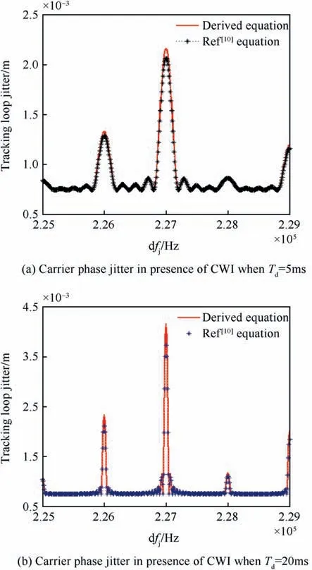
Fig.2. Comparison between the new derived carrier tracking loop phase jitter and that presented in Ref. [8].
It is worth to be noted that the mathematical formula in (3)which describes the CPJ is correct only in the linear region of the loop discriminator when the C/Nois greater than a specific threshold [6]. The GPS receiver interference tolerance depending on the carrier to noise ratio threshold is investigated in the next section.
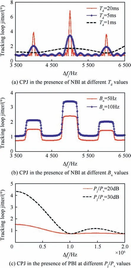
Fig.3. CPJ in the presence of different types of interference signals(CWI,NBI,and PBI).
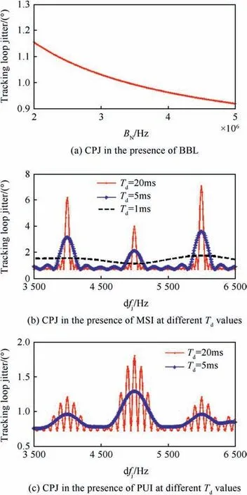
Fig.4. CPJ in the presence of different types of interference signals (BBI, MSI and PUI).
3. GPS receiver interference tolerance and MTLL
For an unaided GPS receiver, the tracking threshold is typically set by the carrier tracking loop.However,when a receiver is aided with Doppler measurements from an Inertial Navigation System(INS), the tracking threshold will be determined by the code loop[3].This is because Doppler aiding allows the numerical controlled oscillator to continue tracking the frequency of the desired signal,even when the carrier loop has been forced to lose lock.
In the following analysis,the receiver is assumed to be unaided and the carrier to noise ratio threshold is assumed to be determined by the carrier loop.
In order to analyse the GPS receiver interference tolerance (KI),the carrier to noise ratio threshold should be firstly analyzed. The carrier to noise ratio threshold is defined as the minimum required C/Noat the correlator output that is sufficient to maintain a stable lock with a tracking error variance lower than a specific threshold[11]. The tracking loop exhibits the characteristic that, if the tracking error exceeds a certain boundary threshold, the tracking loop will no longer be able to track the signal and will loss lock[3].This is because the characteristics of the carrier tracking loop discriminators are nonlinear,especially near the threshold regions[8].A conservative rule of thumb for tracking loop is that the 3-sigma phase jitter must not exceed 1/4 of the phase pull-in range of the carrier tracking loop discriminator, it can be written as [3].

where α is the phase pull-in range.By substituting (3) into (11)

where [C/No]this the carrier to noise ratio threshold.
A receiver is unable to keep track of signals if the postcorrelation C/Nodecreases below that threshold. From(12), [C/No]thcan be derived as

The phase pull-in range of a Costas (the arctangent discriminator) loop discriminator is equal to ±π/2, whereas a pure phase locked loop discriminator has a pull-in range of±π[4].For the case where there is data modulation,the Costas loop is used.Therefore the Costas loop cannot tolerate phase jitter greater than 15°during the total dwell time [12].
The [C/No]thin case of Costas loop can be written as

From(14),it can be seen that,the carrier to noise ratio threshold decreases by decreasing the loop noise bandwidth or increasing the integration time.
The GPS receiver interference tolerance (KI) is defined as the maximum interference to useful GPS signal power at the input of the receive antenna that the GPS receiver can tolerate (does not cause loss of lock, and can determine its position). When the interference to the GPS signal power is greater than the receiver interference tolerance value,in such case C/Nodrop to be less than the carrier to the noise ratio thresholdand the carrier tracking loop lose the locking of the GPS signal.Then,the required interference power to cause loss of lock can be calculated for a typical receiver.
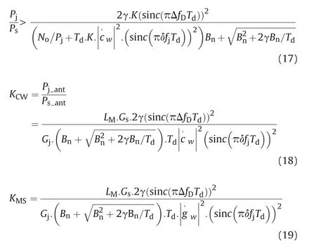
From (4) and (13) in the case of CWI, the GPS receiver cannot determine the position when the CWI to GPS signal power at the correlator output is greater than the specific threshold (see (17))
The interference power Pjwill be assumed much greater than the noise power density No, thus the term No/Pjin (17) can be ignored.

The GPS and interference signal power at the correlator input can be written as:tis the received GPS signal power at the antenna input,Gsis the GPS receiver antenna gain toward the satellite, Liis the receiver implementation loss including analog to digital converter

The GPS receiver MSI tolerances can be derived as: (see (19)).The GPS receiver PUI tolerances can be derived as (22).
The MTLL should be determined to analyse the interference effect on the GPS receiver.The time to lose lock(TLL)is defined as the minimum time required for the C/Noto be less than the carrier to noise ratio threshold. This happens at that time when the carrier tracking loop is no longer be able to track the GPS signal and the loss of lock is occurred[13].TLL is a random variable and the mean value of TLL is the MTLL [11].
When the post-correlation C/Nois less than[C/No]thfor time less than MTLL,this does not guarantee that the loop will lose lock,and the probability of loss lock will be small.The probability of loss lock will become very high when the post-correlation C/Nostay less than [C/No]thfor time longer than the MTLL value.
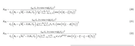
Unfortunately,the MTLL value is difficult to obtain theoretically,as tracking loops are non-linear in the threshold region. Simulations are usually used in order to establish the true tracking performance,and determine the MTLL value.The average value of TLL is taken over several simulation runs. (see (20), (21), (22)).
The MTLL is determined as:loss,LMis the pre-correlation mitigation factor for the interference signal, Pjantis the received interference power at the antenna input, Gjis the antenna gain in the direction of the interference source.
Finally the CWI tolerances can be written as (see (18))
When the interference power is high than the GPS signal power with enough value greater than CWI tolerance it will cause loss of tracking,and re-acquisition is required.
Using the same steps, the GPS receiver NBI tolerances can be derived as in(20).The GPS receiver PBI tolerances can be derived as(21). The GPS receiver BBI tolerances can be derived as (16)

4. Simulation and numerical results for the third order carrier tracking loop
This section introduces a simulation model for the third order Costas carrier tracking loop, with noise bandwidth of carrier tracking loops Bn= 5 Hz, and the damping ratio was set to 0.707.The coherent integration time takes values (1-20 ms); the noncoherent integration value is fixed to K = 1. For a fair comparison the code phase estimate error is set to Δτ = 0, and the reference code in the GPS receiver is PRN1.
4.1. The carrier tracking loop phase error and carrier to noise ratio threshold
The tracking loop phase error is evaluated at different carrier to noise ratio in order to investigate the carrier to noise ratio threshold.
In Fig.5,the carrier loop phase error is evaluated at different C/Novalues (from 15 to 40 dB-Hz) by using the simulation model,during (6000Td= 120s), when Td= 20ms.
It has to be noted that, the loop rate equals to fL= 1/Td=fs/Ns, thus, the loop output phase error will be evaluated once every integration time. By decreasing the C/Novalue the tracking phase error is increased,and the tracking loop remains able to track the signal until the C/Novalue be less than a specific threshold(20 dB),after that the tracking loop suffers from loss of lock on the input signal.
Fig.6 depicts the analytical and simulation carrier tracking jitter at varies C/Novalues (10-45 dB), in order to compare among simulation and analytical results using Equation (3) and to determine the value of [C/No]th.
Fig. 6 shows the agreement between the simulation and analytical results. The gap between the analytical and simulated results broadens suddenly and becomes very large.
When the phase jitter approaches a certain value, after this value the tracking loop enters the non-linear state and the linear assumption cannot be valid. The vertical trend in the curve computed from the simulation tracking error indicates that the loop has lost lock. This phenomenon is not predicted by the theoretical jitter model (3) and (11) which based on a linear approximation of the loop. Also, it was found that the simulation value of the carrier to noise ratio threshold [C/No]th=21.4 dB when the phase jitter equals to 13.7. Yet, analytically from formula (11) the[C/No]th=20.5 when the phase jitter equals to 15o(that gives a good agreement among simulation and analytical results).
4.2. The GPS receiver interference tolerance
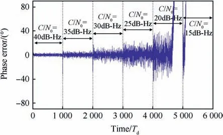
Fig. 5. The carrier tracking phase error at varies C/No values.
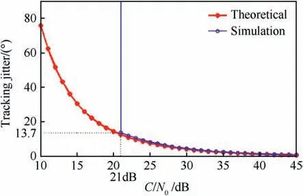
Fig. 6. Theoretical and simulation comparison of the carrier tracking jitter.
Fig. 7 depicts the CWI tolerances when the integration time is varied from 1 to 20 ms. The interference frequency error has two values Δfj= 42 and 42.048 kHz, as shown in Fig. 7a and Fig. 7b,respectively.From Fig.7a,it is shown that when the CWI frequency coincides with the C/A spectral-lines (Δfj=42 kHz) and the integration time Td= 20 ms, in this case if
, it is sufficient to cause loss of lock. But, when Td= 1 ms, themust be greater than 29 dB to cause loss of carrier lock. From fig. 6b, it is shown that in case there is a frequency shift (Δfj= 42.048 kHz),when Td=20 ms,then theneeds to be greater than 48 dB to cause loss of lock.It can be concluded that,when the CWI coincides on the C/A code spectral line, the interference tolerance will be decreased with the increase of the integration time.But,when the CWI is far away from the C/A spectral-lines, in such case the interference tolerance is increased(more power is needed to cause loss of lock)by increasing the integration time.This can be justified as the correlation filter around each spectral line has a bandwidth equals to the reciprocal of the integration time (1/Td).
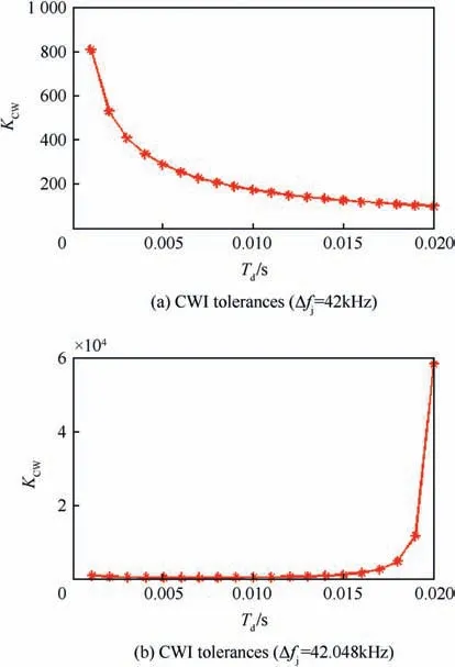
Fig. 7. The CWI tolerances at varies Td value.
For that the correlation filter bandwidth decreases by increasing the integration time.
Fig.8 depicts the CWI tolerances when the loop bandwidth Bn=5 Hz,and the integration time has two values Td=20 and 5 ms and the interference frequency error Δfjis varying from 3.5 to 6.5 kHz.
It is seen that,the width of the CWI influence zone around each spectral line is related to the integration time and equals to 2/Td.When the difference between the CWI frequency and the nearest GPS signal spectral lines δfjis less than the reciprocal of the integration time, in this case the CWI has a significant effect, causes a degradation in the receiver performance and a loss of lock with low interference power (the CWI tolerance KIhas a low value, KI=26 dB when Td=20 ms,KI=31 dB when Td=5 ms,in the case that Δfj=5 kHz).It is noted that the KIvalue is proportional to the C/A code spectral line amplitude.
In another case, when δfjis greater than the reciprocal of the integration time,the CWI needs relatively high power(interference power should be higher than the GPS signal power with value greater than 45 dB to effect the GPS receiver performance. Fig. 9 depicts the CWI, NBI, PBI, BBI tolerances when the integration time Td=20 ms and the interference frequency error Δfjis varying from 40.5 to 43.5 kHz.
In another case, when δfjis greater than the reciprocal of the integration time,the CWI needs relatively high power(interference power should be higher than the GPS signal power with value greater than 45 dB) to effect the GPS receiver performance.
Fig. 10 depicts the MSI tolerance with MSI code phase error Δτp= 5Ta, when the integration time Td=20 ms and the interference frequency error Δfjis varying from 224.5 to 227.5 kHz.
It is shown that in the case that the MSI frequency is identical with the worst CCS spectral line (number 226), the MSI tolerance nearly equals to the CWI tolerance when the CWI frequency is coincident on the C/A worst line.Noted that,when the MSI power is above the signal with 20 dB, it is sufficient to cause loss of lock in the GPS receiver.
In order to verify the interference tolerance derived expression,it will be compared with the simulation results. Fig.11 depicts the carrier tracking loop phase jitter when Pj/Psis varying from 1 to 120. When the integration time equals to 20 ms and the interference frequency error Δfj=42 kHz (the frequency of CWI is closed to the greatest C/A code spectral line).The GPS receiver interference tolerance can be detected by simulation when the phase jitter increases suddenly and becomes very large.
It can be seen that if the CWI power increases above the GPS signal power by nearly 20 dB, the CWI causes loss of lock in the carrier tracking loop (CWI tolerance is equal to 20 dB). This obtained result is the same as the previously derived mathematical result.
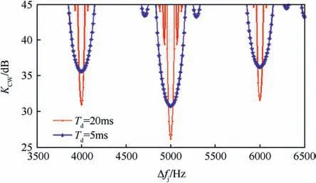
Fig. 8. CWI tolerances at varies Δfj values.
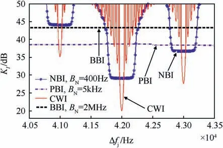
Fig. 9. Comparison among different interference signals tolerance.
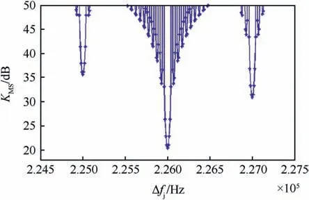
Fig.10. MSI tolerances at varies Δfj values.
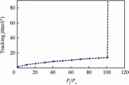
Fig.11. Carrier phase jitter vs Pj/Ps.
Fig. 12 depicts the BBI tolerances with bandwidth equals to 2 MHz,when the integration time Tdis varied from 1 to 20 ms.The loop bandwidth Bntakes three values 5, 10 and 20 Hz and the interference frequency error Δfj= 0 Hz.
It can be seen that by increasing the loop bandwidth Bnor increasing the integration time; the interference tolerance is decreased. When Td=1 ms and Bn= 20 Hz, the PBI tolerance equals to 32.3 dB and this value is close to the value which obtained from laboratory test in Ref. [6].
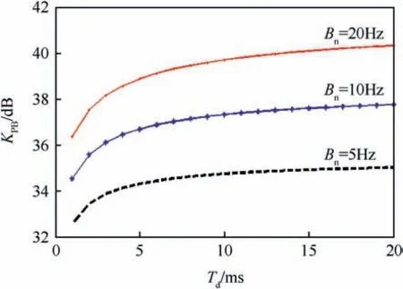
Fig.12. BBI tolerances at varies Td values.
4.3. Mean time to lose lock
It was shown that when the interference to the useful GPS signal power ratio at the antenna is greater than the interference tolerance KIfor time less than the MTLL, this does not guarantee that the loop will lose lock. Simulation was executed to estimate the MTLL for a specific value of the integration time. The interference signal causes a drop in the C/Novalue on the GPS receiver correlator output.Thus,the impact of interference signals on the MTLL can be studied by investigating the effect of the post-correlation C/Noon the MTLL value.
To determine the MTLL in the simulation, the period of time(when C/Noequals to Tm)is increased from Tm=Tdup to Tm= 100Td.Yet, the period of time when C/No=45 dB equals to 1000Tdto guaranty that the carrier tracking loop has a time to return to the locking state.Fig.13 shows the carrier tracking phase error at varies Tmvalues. The loop output phase error will be evaluated once every integration time, and record the Tmvalue when the carrier tracking loop has lost lock (TLL = Tm).
It can also be seen that when Tm=Tdto 52Td(the period of time when C/No<is changed from Tdto 52Td)the carrier tracking loop was able to track the GPS signal.But when Tm=TLL=53Td=1.06s, the loop will loss lock.Fig.14 shows the MTLL for the carrier tracking loop as a function of C/Novalues at different integration time.
It was shown that the MTLL is related to the C/Noand the coherent integration time. The MTLL will increase when the C/No[dB-Hz]or the coherent integration time is increased.When the C/Novalue is varying from 5 to 20 dB-Hz, the value for the MTLL is founded to be changed from 0.5 to 4.2s and from 0.5 to 2.8s when Td=20 ms and 5 ms respectively.
The loop output phase error will be evaluated once every integration time, and record the Tmvalue when the carrier tracking loop has lost lock(TLL=Tm).The MTLL is determined by taking the average value of TLL over several simulation runs.
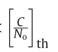
It can also be seen that when Tm=Tdto 52Td(the period of time when C/No<is changed from Tdto 52Td) the carrier tracking loop was able to track the GPS signal.But when Tm=TLL=53Td=1.06 s, the loop will loss lock.
It was found also that when the CWI frequency was coincident with the worst C/A line. A 20 dB CWI power above the GPS signal was sufficient to cause loss of carrier lock. In NBI case the interference tolerance value increased to a 29 dB. For PBI with bandwidth equals to 5 kHz and the interference power was 38.5 dB more than the GPS signal power, in such case the GPS carrier tracking loop was loss of lock.Whereas,for the BBI the tolerance value was 43.1 dB when its bandwidth BN= 2 MHz. Finally, in case that the MSI frequency was coincident with the worst CCS spectral line(number 226),the MSI tolerance value was nearly equal to the CWI tolerance value (only in the case when the CWI frequency was coincident with the C/A worst line). It was shown that, when the MSI power was above the GPS signal with 20 dB,it was sufficient to cause loss of lock in the GPS receiver.
Also it was found that the MTLL value will increase when the C/No[dB-Hz] or the coherent integration time increases.
5. Conclusion
In this paper, closed form analytical expressions for the carrier tracking loop phase error in the presence of different interference signals were derived. The carrier to noise ratio threshold and a novel analytical analysis for the GPS receiver interference tolerance were analytically derived. Also, the MTLL value was determined.The derived analytical expressions were validated with the aid of extensive simulation results.
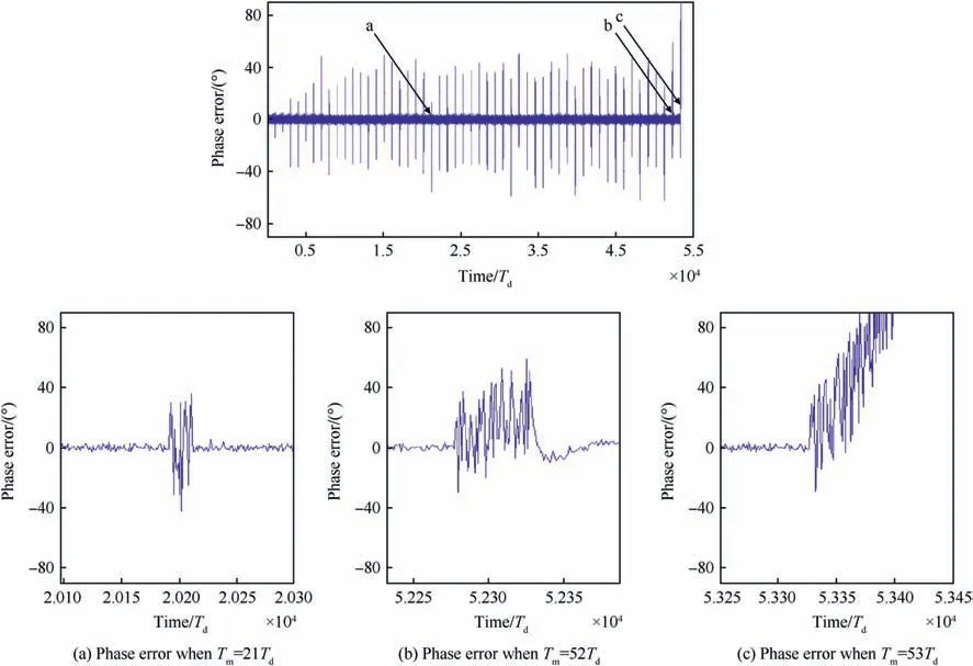
Fig.13. Carrier tracking phase error at varies Tm values.
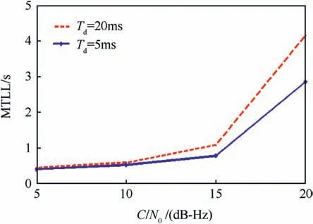
Fig.14. Simulated MTLL of a third order Costas loop.
It was shown that when the difference between the interference frequency and the nearest C/A spectral line was smaller than the reciprocal of the integration time; the CWI has a significant effect on the GPS receiver.In such case the CWI tolerance has a low value and the CWI tolerance value was proportional to the C/A code spectral line amplitude.Whereas,when this difference was greater than the reciprocal of the integration time; the CWI needed a relatively high power to affect the GPS receiver performance.
- Defence Technology的其它文章
- Body armour - New materials, new systems Ian G. Crouch*
- Special materials in pyrotechnics VII: Pyrotechnics used in thermal batteries☆
- Real-time calculation of fragment velocity for cylindrical warheads
- Heavy metal free primers: Polymorphism of gadolinium and titanium in the context of GSR glass phase Felice Nunziata
- Mitigation of EDFA transient effects in variable duty cycle pulsed signals
- Ballistic impact properties of woven bamboo- woven E-glassunsaturated polyester hybrid composites

