Mitigation of EDFA transient effects in variable duty cycle pulsed signals
D. Meen , K.T. Srth , Fredy Frnis , E. Dipin , T. Srinivs
a Electronics and Radar Development Establishment (LRDE), DRDO, Bangalore, Karnataka, 560093, India
b Model Engineering College, Thrikkakara, Cochin, Kerala, 682021, India
c Indian Institute of Technology Madras, Chennai, Tamil Nadu, 600036, India
Keywords:EDFA Transients WDM Variable duty cycle Suppression
A B S T R A C T We report the transient effects in Erbium Doped Fiber Amplifier (EDFA) systems for pulsed signals with different duty-cycles.The work includes the analysis using three different duty-cycles,10%,20%and 50%.A curve fitting technique is also proposed to predict the transients of any lesser duty-cycled pulse, once the transients of a larger duty-cycled pulse is known. Mathematical evaluation confirms the double exponential shape of transient distorted signal. Further, EDFA transient effect is experimentally verified on a Wavelength Division Multiplexed (WDM) link by multiplexing high and low bitrate modulated optical signals.We conclude the paper by proposing a transient suppression technique for variable dutycycle signals and analyzing its effectiveness with different wavelength spacing.
1. Introduction
WDM systems have enabled the transmission of multiple data streams, each modulating a separate optical carrier, along a single optical link. The broad gain spectrum of Erbium Doped Fiber Amplifier (EDFA) is particularly useful in amplifying the WDM signal. Advancements in microwave photonics technology have enabled the efficient transmission of high frequency RF signals through optical links. This have opened up a wide array of novel applications in phased array radar, microwave photonic etc. As Phased array radars require distribution of various signals to more than thousand transmit/receive modules, sufficient signals levels must be ensured before splitting,which can be easily accounted for by using optical amplifiers, EDFA is being the most common used.Additionally, they require the simultaneous transmission of low bitrate variable duty-cycle pulses for control and synchronisation between the elements.The synchronised operation of all Transmit/Receive modules is of greater importance during the operation of a radar system.These low bitrate duty cycle pulses when transmitted through an EDFA, give rise to transients along with distortion [1].This leads to misinterpretation of data at the receiver side. In the case of cascaded EDFA configurations, the transients can accumulate over length and can worsen the scenario. As synchronisation signals used in radars are critical in nature, it is very important to suppress these transients and restore faithful distribution of signals. The objective of this study is to analyze the effect of EDFA transients observed during the amplification of variable duty-cycle signals and propose methods to mitigate these effects.
Transients are the result of slow gain characteristics of EDFA,which induces saturation and recovery effects to low bit rate signals.This is because,the input signal drains the population off the upper level during its ON time and EDFA takes times to replenish the population by pumping. The gain saturation and recovery effects lead to transients and distortion of amplified output. But as the on-time of high bit rate pules are rather short, the change in population inversion and hence gain are rather small. This work reports the simulation and experimental results for EDFA transient effects with different duty-cycle pulsed signals. A transient suppression technique using a complementary signal is also introduced.
Low bit rate pulse causes input signal saturation, which effectively decreases the population inversion by stimulating ions to lower level in large numbers, hence causing the gain to decrease(saturation phase).After the input pulse is removed,the population inversion and hence gain, returns to the initial state (recovery phase).This effect,known as saturation induced gain modulation,is a main source of cross talk in EDFA. The effect was studied and numerically analyzed [2]. Gain saturation and recovery times are discussed with different bit rates and pump levels. It was also proved that the recovery times were reduced with higher pump power.As the saturation and recovery times are rather long,higher bit rate systems are practically unaffected by transient effect. A numerical model of transient response of an EDFA pumped at 1.48 μm, while also considering the gain-saturation effects due to Amplified Spontaneous Emission (ASE) is discussed [3]. Also the paper considered variation in gain with EDFA length. It was again proved that the gain saturation and recovery effects have long time periods of ~2 ms and is dependent on pump power.Pulse distortion due to the recovery time effects are also studied.Additionally,EDFA gain variation for different pulse repetition rate, with high input power and relatively low pump powers, is simulated and 3-dB point of gain saturation was found to be at 20 kHz. EDFA pulse transients for very short, high power, pulses (100ns) have been studied [4], which is expected to be useful for optical memory devices.Pump power(CW,980 nm)dependence of gain saturation for a high power 100ns pulse input pulse is discussed.Pump power dependency of small signal gain and saturation power is also discussed. A pump probe technique is introduced to measure the population recovery in CW pumped EDFA [5]. A double exponent recovery profile was obtained in both their test cases.The change in population inversion caused by the pump signal is probed by the probe signal. A pump-probe technique to obtain the temporal evolution of population inversion in a CW pumped EDFA system is discussed [6]. Temporal profiles for amplified pulses are obtained for different pump and signal power levels. Pump power control can also be used to control the transients [7,8]. Pulse distortion caused by transient effects in a cascaded EDFA configuration is analyzed by altering different parameters like number of cascaded EDFA,peak power and extinction ratio of input pulse[9].In phased array radar applications, low bitrate digital signals are used as reference signals and these signals when transmitted over fiber optic links will have transient effects with respect to dutycycle variations [10]. Control system techniques can be used to control the transients [11,12]. Also, transients create problems in Optical Burst Switching (OBS) networks due to the abrupt power changes in EDFA input power.A feed-forward method to suppress the EDFA transients is discussed [13].
Thus to best of our knowledge, the single shot properties of EDFAs for varied pulse width have not been actively studied.So this work focuses on transient effects of EDFA caused by signals with different duty-cycle and bitrates. Additionally, EDFA transient effects on WDM links are also discussed. We also propose two different Feed forward transient suppressing methods.
2. Experimental set up
Schematic of experimental set up used for single wavelength pulsed signal analysis is shown in Fig.1. Except EDFA, the setup is made from components (shaded) available as part of commercial WDM test unit. A 1530 nm laser diode (1 mw) is modulated by a variable duty-cycle digital signal of 2 kHz. The laser output is amplified using an EDFA operating in the saturation region with a pump power of 70 mW (980 nm). The output is then fed to photodetector of WDM unit and electrical signal is observed using Digital Phosphor Oscilloscope (DPO).
To evaluate dependency of transient effects on duty cycle, we used signals of 3 different duty-cycles 10%, 20% and 50%. The measured recovery time(a few hundred microseconds)was found to vary with pump power and input signal frequency. But the dependency of EDFA transients on duty-cycle and bit rate variations alone is considered within the scope of this paper.
A typical transient obtained for a signal of 2 kHz pulse signal is shown in Fig. 2. The spikes at the output signal (yellow, below)caused due to transients are clearly visible. For analysis of EDFA transients with WDM configuration, the schematic as shown in Fig.3 was setup.Pulse signals of frequency 10 kHz and 2.4 MHz are used to modulate the laser sources. A high bitrate(2.4 MHz) pulse signal modulates l510 nm laser source and another a low bitrate(10 kHz) signal modulates a laser source at 1530 nm. An Array Waveguide (AWG) based multiplexer is used for multiplexing of signals. Further this multiplexed output is passed through a 3 dB coupler,where one of the outputs is fed to a photo detector(PD)as reference channel and the other is fed to EDFA.After amplification the signal is fed to another PD for observation.Both PD outputs are analyzed with Tektronix DPO70404B.
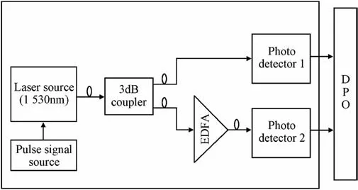
Fig.1. Block schematic of experimental setup for transient measurement (with single wavelength source).
3. Results and discussions
EDFA transient effects in variable duty-cycle(10%,20%and 50%)pulsed signals are analyzed using setup shown in Fig.1.Initially,the transient effects were simulated in a standard simulation environment (OptiSystem). The transients obtained with 10%, 20% and 50% pulsed signals are shown in Fig. 4.
Time dependent population inversion ΔN21(t)is obtained[5]as

where α is the normalized pump power,expressed as Pp/Pth;where Ppand Pthare the pump power and the pump threshold respectively;β is the normalized signal power,expressed as Ps/Psat,where Psand Psatare the signal power and the signal saturation power respectively;τ21is the spontaneous emission lifetime from level 2 to 1.

Also,the dependence of ΔN21(t)on input and output intensities is [5],where Ioutand Iinare input and output intensities respectively. As per equation (2) the power relation can be derived as,

From (1), (2) and (3), Poutcan be expressed as

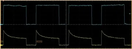
Fig. 2. Transient effect observed at EDFA output (blue) due to a signal input of 2 kHz (yellow). The pulse width is 350μs. The reading values 200 μs per division horizontal and 500 mV per division vertical.
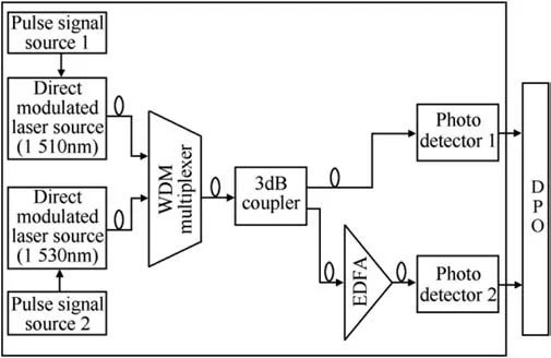
Fig. 3. Block schematic of experimental setup for WDM link transient measurement(with low and high bitrate signals).
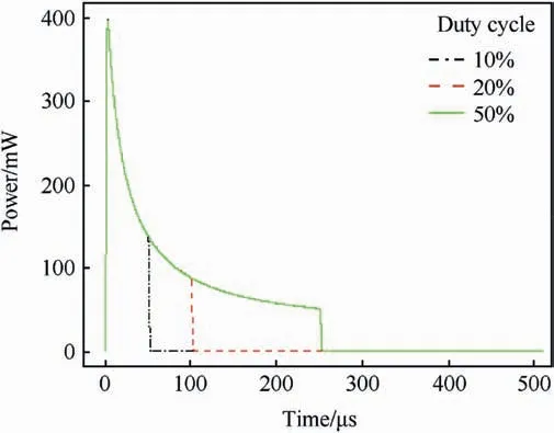
Fig. 4. Transients variations for 50% (Green), 20% (Red) and 10% (black) single wavelength input.
where K1and K2are constants. So, it can be seen that Poutis following an exponential curve proportional to exp(exp(-K2t)).The results obtained in Fig. 4 was further curve fitted using an exponential function of degree 2. The fitted curve was found to have a very low RMSE (Root Mean Square Error) of order 10-3, proving simulation results to be exponential and hence correlating well with equation (3) and (4). The simulated transient curves (Black)and fitted curve (blue) for 50% duty-cycle pulse signal is given as shown in Fig. 5.
It was further observed that the transient curves of 20%and 10%duty-cycle overlap with that of 50% up to their corresponding ON time. This means that transient response for any lower duty-cycle can be predicted from that of higher duty-cycle output signal.This shows that the curve fitted equation of 50% signal can in general be used for finding transients of any lesser pulse widths.Table 1 gives a comparison of output signal obtained from actually fitted curves of 10% (Fig. 6) and 20% (Fig. 7) signals along with corresponding values deduced from curvefit equation of 50%dutycycle signal transient.
It can be observed that the error between predicted and individual curve fits values are of the order of 10-4.
Another analysis is performed to validate the simulation results against experimental results by plotting the duty cycle vs decay rate as shown in Fig.8.It can be observed that decay rate decreases with experimental results also as in the case of modeling results.
4. Transient suppression technique
As transient effects negatively impact the pulse shape at the output of the link, it can lead to misinterpretation of data. Also, in cascaded EDFA applications, the transients can accumulate over length and can cause problems at detector. The objective of transient suppression technique is to enable the faithful detection of the input signal at the output. The proposed methods intent to do this by trying to avoid signal distortion at EDFA stages by keeping the net input through EDFA constant all the time. To accomplish this, an additional signal having a complementary shape is also multiplexed in to the link at a different wavelength which ensures the EDFA input power remains constant.But the previous work[9]mentions about a single pulse of duty-cycle of the order 10-4only.Fig. 9 shows the block schematics of the setup which can be used for suppression of transient associated with variable duty cycle signals.
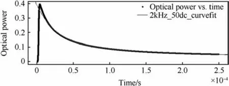
Fig. 5. Transient effect with 50% duty-cycle signal (blue) and corresponding fitted curve (black).

Table 1Comparison of individual curvefit amplitude (10%and 20% signal) with predicted values obtained from 50% signal curvefit.
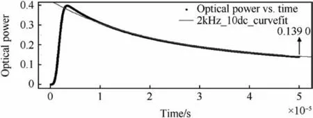
Fig. 6. Transient effect with 10% duty-cycle signal (blue) and corresponding fitted curve (black).
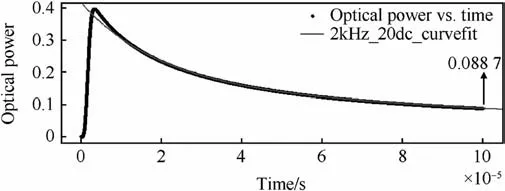
Fig. 7. Transient effect with at 20% duty-cycle (blue) and corresponding fitted curve(black).
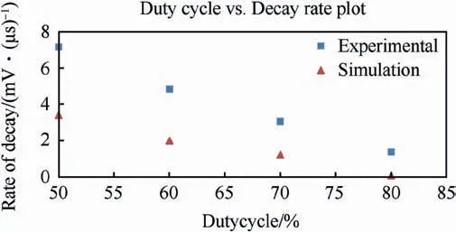
Fig. 8. Comparison of Experimental and modeling results - Decay rate vs Duty cycle.
The effects of compensation on signals with different dutycycles are shown in Fig.10. It can be observed that the transients settle down rather quickly after the first pulse with the presence of complementary pulse. This might affect the amplitude of the output signal, but as digital pulses are relatively insensitive to signal to noise ratio,it can easily be regenerated and amplified.The effect of complementary signal will be prominent from the negative edge of first transmitted pulse.
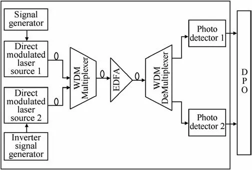
Fig. 9. Block schematic of the setup for EDFA transient suppression using complementary signal.
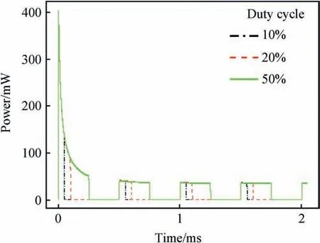
Fig.10. Transient suppression by complementary pulse for different duty-cycles.
Fig.11 shows the block schematic that can be used for transient suppression of 50% duty cycle signal. The delay introduced should be equivalent to the ON/OFF time of transmitted signal. The experimental result obtained for compensation using optical delay line is shown in Fig.12.
We also found that the wavelength of compensation signal affects the actual transient suppression process. The closer the compensation wavelength (to the signal wavelength), the better the compensation will be. This is clearly visible in Fig. 13, where compensation pulse at 1570.8 nm (black) was found to be more effective than those at 1575 nm(red)and 1590 nm(Green).In this case the signal wavelength was at 1570 nm.
We also analyzed transient effect with WDM signals. Additionally,as a part of experimental verification of the simulation results,a WDM configuration as in Fig.3 was setup.In this case,two laser sources of wavelengths 1510 nm and 1530 nm signals are used.Laser Source of wavelength 1510 nm is modulated by a high frequency signal of 2.4 MHz and source with 1530 nm is modulated by a low frequency signal of 10 kHz respectively. Snapshot of setup is shown in Fig.14.
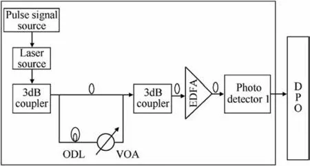
Fig.11. Block schematic of the setup for EDFA transient suppression using optical delay line.ODL-Optical Delay Line,VOA-Variable Optical Attenuator,DPO-Digital Phosphor Oscilloscope.
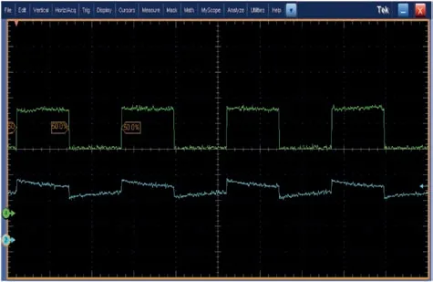
Fig. 12. Experimental result of suppressed transients (blue) for low bit rate input(green) using delay line method.
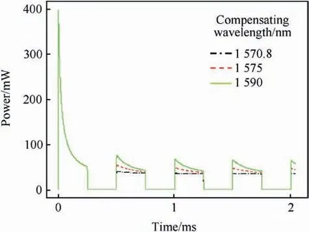
Fig.13. Variation in transient suppression with different wavelengths.
Fig.15 shows results obtained with DPO, the high to low transition shown is the 10 kHz signal's negative edge.Up to the negative edge,the effect of 10 kHz signal is more prominent,as shown by the absence of oscillations at 2.4 MHz. During the negative cycle of 10 kHz signal,the amplifications are obtained for 2.4 MHz signal as shown by the oscillation in the lower part of the signal.
Simulation results obtained for the same setup in Fig. 14 is shown in Fig.16.It can be seen that the results are similar too.The low bit rate pulse is found to suppress the amplification of higher bit rate pulse during its ON period. So the 2.4 MHz signal have output only during the OFF period of 10 kHz signal.
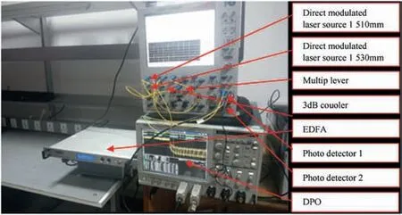
Fig. 14. Experimental Setup showing transients in WDM multiplexed high and low frequency signals.
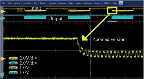
Fig.15. Transients in WDM link: WDM input (blue) and output (yellow-zoomed).
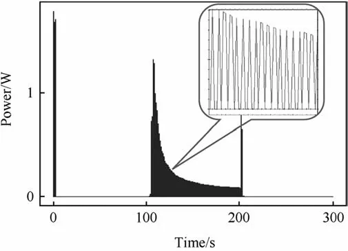
Fig.16. Transient effect in high bit rate channel WDM link: Simulation result.
5. Conclusion
Many applications,like radar distribution network,demand the transmission of pulses with different duty-cycles. It's known that the slow gain response of EDFA leads to transients effects at the amplified signal.We analyzed the variation of transients for signals with different duty-cycles and found that the transients can in fact be predicted by knowing the transient curve of a larger duty-cycle pulse.Additionally,we have analyzed the transient effect in a WDM link consisting of high and low bitrate pulse signals, each modulating lasers at different wavelengths and multiplexed into EDFA.The observed transient effect was particularly prominent during the negative edge of low bit rate pulse as proved by simulation and experimental studies. We also bring out two methods to suppress transient effect which uses complementary signal pulse modulating a laser at a different wavelength. It was also found that the nearer the compensation wavelength, the better the transient suppression.
- Defence Technology的其它文章
- Body armour - New materials, new systems Ian G. Crouch*
- Special materials in pyrotechnics VII: Pyrotechnics used in thermal batteries☆
- Real-time calculation of fragment velocity for cylindrical warheads
- Heavy metal free primers: Polymorphism of gadolinium and titanium in the context of GSR glass phase Felice Nunziata
- Ballistic impact properties of woven bamboo- woven E-glassunsaturated polyester hybrid composites
- Experimental investigations on wear properties of Palm kernel reinforced composites for brake pad applications

