A three-stage model for the perforation of finite metallic plates by long rods at high velocities
Yu He , Liu-yun Xu , He-ming Wen ,*, Zheng-cao Lu
a National Key Laboratory of Shock Wave and Detonation Physics, Institute of Fluid Physics, CAEP, Mianyang, 621900, China
b CAS Key Laboratory for Mechanical Behavior and Design of Materials, University of Science and Technology of China, Hefei, Anhui, 230027, China
Keywords:Perforation Long rod Finite metallic plate Ballistic limit Residual velocity Residual length
A B S T R A C T A three-stage theoretical model is presented herein to predict the perforation of a thick metallic plate struck normally by a long rod at high velocities. The model is suggested on the basis of the assumption that the perforation of a thick metallic plate by a long rod can be divided into three stages: (1) initial penetration; (2) plug formation and (3) plug slipping and separation. Various analytical equations are derived which can be employed to predict the ballistic limit, residual velocity and residual length of the long rod. It is demonstrated that the present model predictions are in good agreement with available experimental results for the perforation of finite steel targets struck normally by steel as well as tungsten alloy long rods at high velocities. It is also demonstrated that the dynamic maximum shear stress of a plate material has strong effect on plug formation and plug thickness which,in turn,exerts considerable influence on the residual velocities and lengths of a long rod at impact velocities just above the ballistic limit.
1. Introduction
Penetration and perforation of solids have been examined extensively for the past half century and especially for the past few decades. However, theoretical effort has been directed mainly towards the penetration of high-speed long rods into semi-infinite targets with much less emphasis being placed on the perforation of finite plates.
Alekseevskii [1] and Tate [2] independently proposed a onedimensional, modified Bernoulli equation which has become the most widely used model for long rod penetration into semiinfinite targets.The A-T model assumes that the materials of both penetrator and target near the interface behave as fluid while the rear of the projectile remains rigid. Furthermore, the transition from rigid to fluid is ignored. DOP (depth of penetration) can be calculated using the A-T model, together with equations for erosion rate and deceleration of the projectile. In other words,the essence of A-T model is how to determine the penetrator strength Ypand the target resistance Rt. By curve fitting to the experimental data,Tate[1,3]pointed out that Ypand Rtare of the same order of magnitude with the Hugoniot Elastic Limits (HEL)of projectile and target materials, respectively. Rtis several times larger than the yield stress of the target due to lateral confinement.
Many authors have attempted to extend and further develop the A-T model or to propose new ones[4-15].Since the A-T model was established,the determination of target resistance Rtis always the key point. Many publications treated Rtas a constant, which was often determined by curve fitting the predicted DOP to the test data. Moreover, the A-T model with a constant Rtcannot describe well the long rod penetration over a wide range of impact velocities, especially for metallic target. Anderson and Walker [16]pointed out that there is pressure gradient in the region where the pressure is higher than the target strength.Later on,Anderson and Walker[17]investigated the target resistance under various impact velocities by curve fitting the A-T model predictions to the experimental data for tungsten alloy long rod penetration into semiinfinite armor steel targets. It was found that Rtis not a constant but a function of impact velocity when impact velocity exceeds 1.5 km/s. Hence, the constant Rtemployed in the A-T model does not reflect the real response of the target in the long rod penetration.
Wen and co-workers[18-23]has recently established a unified theory for long rod penetration in which Rthas explicit form and is a function of penetration velocity and thermo-mechanical properties of target material. Depending upon the relative magnitude of long rod dynamic strength (Yp) to target static resistance (S), long rod penetration can be generally divided into two categories,namely, scenario I: Yp≤S and scenario II: Yp>S; three critical velocities(i.e.interface defeat velocity VID,rigid body velocity VRand hydrodynamic velocity VH) have been defined theoretically to describe the transitions among the different modes of penetration(i.e. interface defeat, rigid body penetration, deformable penetration and erosive penetration). It has been found that the model predictions are in good agreement with the experimental observations in terms of mode of penetration,the u-v relationship,depth of penetration,crater diameter and residual length.It has been also found that the A-T model is only a special case of the present unified theory when impact velocity goes to infinity.
The perforation of finite metallic plates struck normally by highspeed long rods has received much less attention in terms of theoretical investigation.Grace[24,25]proposed a model in which the force acting on each side for a given penetrator and target was assumed to be constant by introducing “finite mass” in the target material around the penetration centerline which interacts with the penetrator. The model predictions were shown to be in reasonable agreement with the experimental results for the perforation of thin metallic plates struck by long rods at high velocities. However, the model predictions were found to in poor agreement with the test data for perforation of thick metallic targets.Anderson[26]investigated the perforation of long tungsten alloy rods into high-hard steel finite targets and wave code CTH was used to numerically simulate the experiments. Also the Lambert equation was used to estimate the ballistic limit by fitting experimental data.
The objective of this paper is to present a theoretical model for the perforation of thick ductile metallic plates struck normally by long rods at high velocities. The present model is based on the newly suggested models of long rod penetration and adiabatic shear plugging and the experimental observations that the perforation process of a finite metallic plate by a high speed long rod can be divided into three stages: (1) penetration; (2) plug formation and (3) plug slipping and separation. Various equations are obtained which can be used to predict ballistic limit,residual velocity and residual length of the rod perforating the finite metallic plate.The model predictions are compared with available experimental results and discussed.
?
2. Formulation of a three-stage model
Different failure modes may exist in the perforation of a metal plate by a projectile depending upon a combination of parameters such as the geometrical (e.g. projectile diameter, projectile nose shape, plate thickness) and thermo-mechanical properties (e.g.projectile and plate strengths/hardnesses) of both the projectile and the plate as discussed by Ravid and Bodner[27],Wen and Jones[28],Anderson et al. [29],Børvik et al. [30],Sun and Wen[31]and others.In particular,a ductile metal plate under impact by a bluntended missile can fail either by global deformation (dishing)combined with local shear rupture or by localized adiabatic shear plugging as discussed by Wen and Jones [28], Sun and Wen [31].Furthermore,Sun and Wen[31]proposed a criterion which can be used to determine the critical condition for differentiating localized adiabatic shear plugging from simple shear plugging failure with global deformations.In the present paper,a three-stage model was suggested where the first phase is characterized by erosive penetration stage,which means that the plates examined are relatively thick,at least thicker than the critical thickness at which adiabatic shear plugging occurs,as predicted by the model suggested by Sun and Wen [31].
Fig.1 shows schematically the three stages of a finite metallic plate perforated by a long rod at high velocity, namely, (a) penetration; (b) plug formation and (c) plug slipping and separation.Various equations are derived for each stage by closely following the recent studies on long rod penetration and adiabatic shear plugging.
2.1. Penetration
Fig.1(a)shows the penetration stage of a long rod into a finite metallic target.In this stage,it is assumed that the rod will behave in the same way as it does in a semi-infinite metallic target as shown schematically in Fig.2 where l is the length of the rigid part of the rod, A0is the initial area of the cross section of the shank with a radius of r, and L0, V0are the initial length and impact velocity of the rod, respectively. The penetrator will penetrate in an erosive manner and the head of long rod penetrator becomes mushroom-shaped. With the penetrator being continuously eroded(i.e.,in the quasi-steady penetration stage)the material of the rigid part(tail)of the penetrator flows into the mushrooming head and the erosion products of the long rod penetrator. Under very high velocity penetration, shear stress can be ignored and material behaviour near the projectile-target interface can be approximated as hydrodynamic, viz. the materials near the interface can be treated as fluid [18,23] (this is the basic assumption of the original A-T model).
The momentum balance of the rigid part of the rod gives [2]
and the rod erodes [2] as

where ρpis the density of the projectile, t is time, Ypand l are the dynamic strength and length of the projectile,respectively.v is the rear velocity of the projectile and u is the penetration velocity which can be determined by the following equations, viz [18,21].

or

with δ(u) being defined by

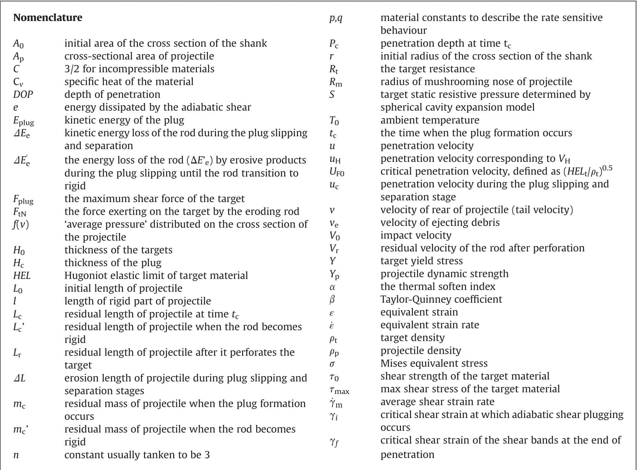
where ρtis target density,S is the static resistance of the target,C is a constant of the dynamic resistive pressure and for incompressible materials, C=3/2, UF0is the critical penetration velocity above which a fluid-like flow region appears in the target near the penetrator-target interface, otherwise there are only plastic and elastic regions and UF0=where HEL is the Hugoniot Elastic Limit of the target material [18].
From equations(1)and(2),the relation of l and v can be derived,i.e.

Fig.1. Schematic diagram showing the three stages of plate perforation by a long rod at high velocity: (a) penetration; (b) plug formation and (c) plug slipping and separation.
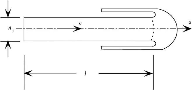
Fig. 2. Schematic diagram of an eroding long rod penetrating a target.

The depth of penetration is

Combining equations (1), (6) and (7) and rearranging gives

In which the relations of u and v are determined by equations(3)-(5). The force (FtN) on the target by the eroding rod is determined as [20]

2.2. Plug formation
It is assumed that when the maximum shear force(Fplug)of the target is equal to the force exerting on the target by the eroding rod(FtN)a plug will be formed with a radius of Rmequal to the radius of the mushroom head of the rod and a thickness of Hc, as shown schematically in Fig.1(b), namely[31]

The force exerting on the target by the eroding rod (FtN) is estimated by equation (9). The max shear force (Fplug) can be evaluated by

where τmaxis the max shear stress corresponding to the critical shear strain at which adiabatic shear plugging occurs and it can be determined by taking the extremum of shear strain through a thermos-viscoplastic constitutive relationship under adiabatic condition, namely[31]

where τ0is the shear strength of the target material when shear strain (γ) equals 1(γ=1), n is the strain hardening index, p and q are empirical constants which are used to describe the rate sensitive behaviour of the target material,α is the thermal soften index,T0is ambient temperature, Cvis specific heat, β is the Taylor-Quinney coefficient, ˙γmis average shear strain rate which is related to the velocity of the plug (u) by the following expression

γiin equation (12) is the critical shear strain at which adiabatic shear plugging occurs and is determined by the following expression. (for more details, see Ref. [31])

Combining equations (9), (11)-(14) and rearranging yields the critical thickness of the plug, viz

where subscript c denotes the values of various parameters at the time when the plug formation occurs (tc), ucis the penetration velocity determined by equations (3)-(5) and Rmis the radius of mushroom head of the rod which can be estimated by the following equation

As shown in Fig.1(b),the penetration depth(Pc)of the target at the time tccan be estimated by the following expression

The mass of the plug can be determined as

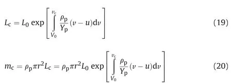
The residual length (Lc) and mass (mc) of the rod can be evaluated by the following equations
2.3. Plug slipping and separation with erosive rod
It is assumed that the penetration velocity (uc) remains unchanged during the plug slipping and separation stage and that the plug will be accelerated by the rod until the velocity of the plug is

where veis the velocity of rod erosion products which can be determined by Ref. [20]

From the energy conversation,the kinetic energy loss of the rod during the plug slipping and separation is transformed to the energy dissipated by adiabatic shear band in the target and the kinetic energy of the plug when the target is perforated,viz

Substituting equations(21),(22)and(25)into equation(26)and rearranging gives

The total residual length of the rod after it perforates the target is

equal to the penetration velocity. Hence, the kinetic energy of the plug is

The energy dissipated by the adiabatic shear plugging can be determined as [30]

where γfis the critical shear strain which can be estimated by the following equation

Both experiments and numerical simulations indicate that the rod will continue to be eroded. Let the erosion length be ΔL, then the kinetic energy loss of the rod(ΔEe)during the plug slipping and separation is
In this stage, velocity of the rod (v) will decrease due to the elastic wave transmitted in the rod.From equations(1)and(2),the relationship between the velocity(v)and residual length(l)can be obtained as

By integrating equation (29) at the plugging slipping and separation stage the residual velocity of the rod after perforation can be estimated as

The assumption that the rod will perforate the target with erosion state demands that, the velocity of residual rod (vr) is higher than penetration velocity (uc) in equation (28) during plug slipping stage, viz

2.4. Plug slipping and separation with rigid rod
As the residual rod decelerating during the perforation stage,the rod becomes rigid when the residual velocity (v) equals to uc.The residual lengthand massof the rigid rod can be evaluated by the following equations

Then the energy loss of the rod(ΔE′e)by erosive products during the plug slipping until the rod transition to rigid is

From the energy conversation,the residual kinetic energy of the rod when the plug is formed is equal to the sum of the energy loss of the erosive rod products, the energy dissipated by adiabatic shear band and the residual kinetic energy of the rod and plug when the target is perforated,viz

Hence, from equation (35) one obtains the residual velocity of the rod after perforation, viz

It should be mentioned here that when the residual velocity of the rod is equal to zero,then the corresponding impact velocity of the rod is the ballistic limit (Vbl).
3. Comparisons and discussi on
In the following the model developed in the above section is compared with available test data in section 3.1 and the influence of constitutive properties on the plate perforation is discussed in section 3.2.
3.1. Comparisons with available experimental data
Experimental data for the perforation of steel targets by C110W1 steel and tungsten alloy long rods were reported by Hohler and Stilp [32]. On the one hand, the tungsten alloy rods had 294 BHN and the rod length and diameter were 58 mm and 5.8 mm,respectively (i.e. L/D=10). The steel plates had 415BHN. On the other hand,the two C110W1 steel rods used in the experiments had 199BHN and 401BHN. The length and diameter of the steel rods were also 58 mm and 5.8 mm,respectively(i.e.L/D=10).Also,two kinds of steel targets were utilized in the experiments which had 415BHN and 460BHN. In the experiments, the impact velocities ranged from 945 m/s to 2046 m/s.
From the Mises yield rule, the following relations are obtained,namely,τ =σ/3,ε=γ/3and ˙ε = ˙γ/3where σ,ε and ˙ε are the Mises equivalent stress,equivalent strain and equivalent strain rate.Ballistic response is sensitive to the target constitutive properties and, strictly speaking, the values of various parameters and, in particular, the parameters describing the effects of strain rate and temperature on the strength of the armour steels examined by Hohler and Stilp[32]should be used in the theoretical calculations.Unfortunately,these information was not available in the literature.Hence, the values of the parameters describing the constitutive behaviour and especially the effects of strain rate and temperature on the strength of a high strength steel reported by Rohr et al.[33]are employed instead which are similar to those obtained for the Weldox 460E steel investigated by Borvik et al. [30]. The comparison of these two materials in terms of constitutive behaviour is given as Appendix.Thus,the values of various material parameters of armour steel targets in the calculations are taken to be n=0.25,p=8.0×10⁷s-1, q=7.33,α=6.8×10⁻⁴, Cv=452J/kg⋅K, T0=293K[31].The yield strengths of both tungsten alloy and steels were not given by Hohler and Stilp [32] except for the Brinell hardness number (BHN) which can be employed to calculate the tensile strengths of these materials using the formula UTS =6.84×(BHN-11.24)/1.979MPa.Hence,in the calculations the yield strength(Y)of the bi-linear material model used in the present model is assumed to be taken as Y =0.9UTS and the values of the yield strengths(Y)and the tensile strengths(UTS)of these materials are listed in Table 1.Also listed in Table 1 are the values of the material parameter (τ0) which is the shear strength at γ = 1with γ being shear strain[31].
Fig. 3 shows the experimental data for the relationships between residual velocity and impact velocity for the D17 tungsten long rods perforating steel plates[32].Also shown in the figure are the present model predictions. It is found from Fig. 3 that the present model predictions are in good agreement with the experimental data. It is also found from Fig. 3 that the differences between the residual velocities for the 20.6mm/20.9 mm and 40.0 mm thick steel plates are decreasing with increasing impact velocities, the greater the impact velocity, the smaller the difference between the residual velocities. It should be mentioned here that the ballistic limits as predicted by the present model are also in good agreement with the test results.for instance,for the 20.6 mm thick steel plate,its ballistic limit as predicted by the present model is 970 m/s which lies between 945 m/s without perforation and 1064 m/s with perforation as observed in the experiments.
Fig. 4 shows the experimental results for the relationships between residual length and impact velocity for the D17 tungsten long rods perforating steel plates[32].Also shown in the figure are the present model predictions. It is evident from Fig. 4 that the present model predictions are in good agreement with the experimental results for the 20.6 mm and 20.9 mm thick steel plates whilst for the 40.0 mm thick steel plate the present model underestimate a little bit the test data. It is also evident from Fig. 4 that the dimensionless residual length of a tungsten alloy long rod increases with increasing impact velocity;that it reaches a peak value at about 1800 m/s and then decreases with increasing impact velocity. The residual length of a long rod is mainly related to the thickness of a plate.At an impact velocity of 2000 m/s,the residual length of the tungsten alloy long rod perforating the 40.0 mm target is nearly a half of those perforating the 20.6 mm and 20.9 mm plates.
Fig. 5 shows the experimental data for the relationships between residual velocity and impact velocity for the C110W1 steel long rods perforating steel targets[32].Also shown in the figure are the present model predictions. It is demonstrated from Fig. 5 that the present model predictions are in good agreement with the test data in terms of residual velocities.At the vicinity of ballistic limit,for the scenario of BHNp=199, BHNt=415, the ballistic limit predicted by the present theoretical model is 1550 m/s, which lies between 1415 m/s without perforation and 1649 m/s with perforation as observed in the experiments; for the scenario of BHNp=199,BHNt=460,the ballistic limit predicted theoretically is 1630 m/s, which lies between 1395 m/s without perforation and 1770 m/s with perforation as observed in the experiments. hence,the present model predicts well the ballistic limits for these two scenarios even though only a few test data points are available. In the case of BHNp=401,BHNt=460,the ballistic limit calculated by the present model is 1500 m/s,which is about 7%higher than that observed in the experiment (the ballistic limit lies between 1410 m/s to 1422 m/s).It should be mentioned here that if the real values of the yield strengths are used in the calculations the theoretically predicted ballistic limits can be further improved as compared to the test data.

Table 1The constants of projectile and target materials.
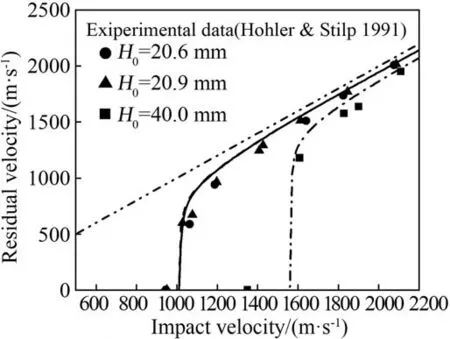
Fig. 3. Comparison of the present model predictions with the experimental dada for the residual velocities of D17 tungsten alloy long rods perforating steel plates [32]. --:H=20.6 mm;-: H=20.9 mm;-. -: H=40.0 mm.
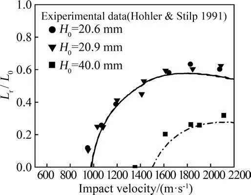
Fig.4. Comparison between the present model predictions and the test results for the residual lengths of D17 tungsten alloy long rods perforating steel plates [32]. --:H=20.6 mm;-: H=20.9 mm;-. -: H=40.0 mm.
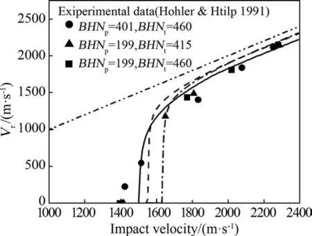
Fig. 5. Comparison of the present model predictions with the experimental dada for the residual velocities of C110W1 steel long rods perforating steel plates [32]. - -:BHNp=199,BHNt=415;-: BHNp=401,BHNt=460;-. -: BHNp=199,BHNt=460.
It is also demonstrated from Fig.5 that greater strength long rod is easier to perforate a plate(lower ballistic limit)and that effects of the strengths of both long rods and plates on the residual velocities decrease with increasing impact velocities with higher strength long rods having slightly lower residual velocities as compared with lower strength long rods.This is because that at much higher impact velocities a greater strength long rod will decelerate faster than a lower strength long rod due to the fact that the greater strength long rod will experience larger resistive force as can be seen from equation(1),which will result in a lower tail velocity or residual velocity.
Fig. 6 shows comparisons between the theoretical predictions and the experimental results for the residual lengths of C110W1 steel long rods perforating steel targets. Also shown in the figure are the present model predictions. It is clear from Fig. 6 that the present model predictions are in good agreement with the experiment results for the two scenarios (i.e. BHNp=199,BHNt=415;BHNp=199,BHNt=460). In the case of BHNp=401,BHNt=460,reasonable agreement is obtained between the present model predictions and the test data for impact velocities greater than 1600 m/s whilst for impact velocities less than 1600 the present model under-estimates the experimental results. This is because the present model over-estimates a little bit the ballistic limits as can be seen from Fig, 5. Higher strength long rod will result in higher penetration velocity and higher deceleration of the rear part of the rod, which, in turn, will lead to lower erosion velocity and higher residual length.
As discussed before, different failure modes may exist in the perforation of a metal plate by a projectile depending upon a combination of parameters such as the geometrical (e.g. projectile diameter, projectile nose shape, plate thickness) and thermomechanical properties (e.g. projectile and plate strengths/hardnesses)of both the projectile and the plate.For a ductile metal plate under impact by a blunt-ended missile it can fail either by global deformation (dishing) combined with local shear rupture or by localized adiabatic shear plugging as discussed by Wen and Jones[28],Sun and Wen[31].Furthermore,Sun and Wen[31]proposed a criterion which can be used to determine the critical condition for differentiating localized adiabatic shear plugging from simple shear plugging failure with global deformations. In the present paper, a three-stage model was suggested where the first phase is characterized by erosive penetration stage, which means that the plates examined are relatively thick, at least thicker than the critical thickness at which adiabatic shear plugging occurs,as predicted by the model suggested by Sun and Wen [31].
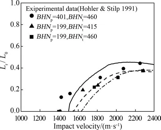
Fig.6. Comparison between the present model predictions and the test results for the residual lengths of C110W1 steel long rods perforating steel plates [32]. - -:BHNp=199,BHNt=415;-: BHNp=401,BHNt=460;-. -: BHNp=199,BHNt=460.
In the present study, a three-stage model has been proposed which consists of erosive penetration, plug formation and plug slipping and separation.The model predicts well for the perforation of steel plates both by D17 tungsten alloy and C110W1 steel long rods except for the case of BHNp=401,BHNt=460 where the present model under-estimates the experimental results for impact velocities less than 1600 m/s and reasonable agreement is obtained between the present model predictions and the test data for impact velocities greater than 1600 m/s. For these relatively strong steel targets, the failure mode might be brittle failure, which is substantially different than adiabatic shear plugging.Furthermore,the range of the applicability of the present model is implied in its formulation, namely, the plate thickness is no less than it critical thickness (Hc) and the impact velocity no less than the ballistic limit (Vc).
3.2. Influence of target material constitutive response
From equation(14),it can be seen that the critical condition for plug formation is related to the max shear stress which is a function of target material strain hardening index n and strain rate hardening index p and q. So residual velocity and plug thickness are related to target material properties/constants.The dynamic shear stress-shear strain relationships for the steel plate material with α=6.8×10⁻⁴, Cv=452J/kg K, T0=293K and τ0=9.907GPa are shown in Fig. 7.
The plug thickness is directly related to the max shear stress as can be seen from equation (11). Fig. 8 shows variation of plug thickness with impact velocity for steel plates with different combination of n, p and q. It can be seen from Figs. 7 and 8 that lower max shear stress results in thicker plug, which means that the perforation resistance of a target will increase with increasing max shear stress of the target material and that higher residual velocities will be obtained especially for impact velocities just above the ballistic limits as shown in Fig. 9. Nevertheless, the differences between the residual velocities for targets with different combination of n, p and q become smaller and smaller as impact velocities get greater and greater.
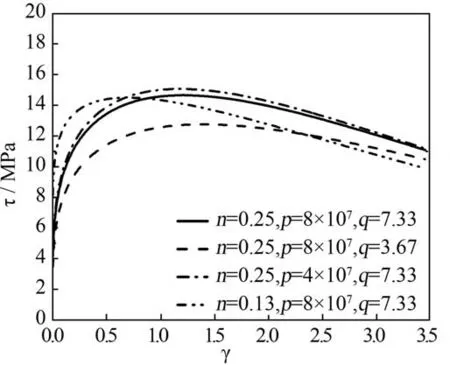
Fig. 7. Dynamic shear stress-shear strain relationships for steel plates with different combination of n, p and q.
4. Conclusions

Fig. 8. Variation of plug thickness with impact velocity for steel plates with different combination of n, p and q.
A three-stage model has been suggested herein to predict the perforation of a finite metallic plate subjected to impact by high velocity long rods at normal incidence. Various equations have been derived and parametric studies conducted to assess the influences of material properties.The main conclusions can be drawn as follows:
(1) The present model predictions are in good agreement with the experimental results for tungsten alloy long rods perforating armor steel plates and in reasonable agreement with the test data for steel long rods perforating armor steel targets in terms of residual velocities and residual lengths.
(2) The dynamic maximum shear stress of a target material has strong effect on plug formation and plug thickness which,in turn,exerts considerable influence on the residual velocities and lengths of a long rod at impact velocities just above the ballistic limit.
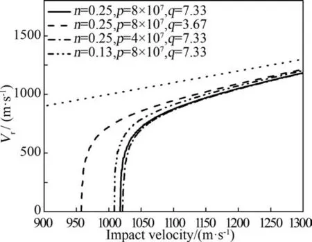
Fig.9. Variation of residual velocity with impact velocity for steel plates with different combination of n, p and q.
Appendix
Ballistic response is sensitive to the target constitutive properties and,strictly speaking,the values of various parameters and,in particular, the parameters describing the effects of strain rate and temperature on the strength of the armour steels examined by Hohler and Stilp [32] should be used. Unfortunately, these information was not available in the literature.Hence,the values of the parameters describing the effects of strain rate and temperature on the strength of a high strength steel reported by Rohr et al.[33]are employed instead which are similar to those obtained for the Weldox 460E steel investigated by Borvik et al. [30].
Fig.A1 shows variation of σd/σ0with strain rate where σ0,σdare the quasi-static yield and dynamic stresses at room temperature,respectively and Fig.A2 presents variation of σT0/σRM0with temperature where σT0,σRM0are the yield stresses at elevated and room temperatures,respectively.It is clear from Figs.A1 and A2 that the influences of strain rate and temperature on the normalized yield stress both for the Weldox 460E steel examined by Borvik et al.[30]and the high strength steel investigated by Rohr et al. [33], follow the same trend and the difference between these two steels are negligibly small. Hence, in the theoretical calculations of the present paper the material data for the high strength steel [33] have been adopted to describe the constitutive response of German RHA steels approximately.
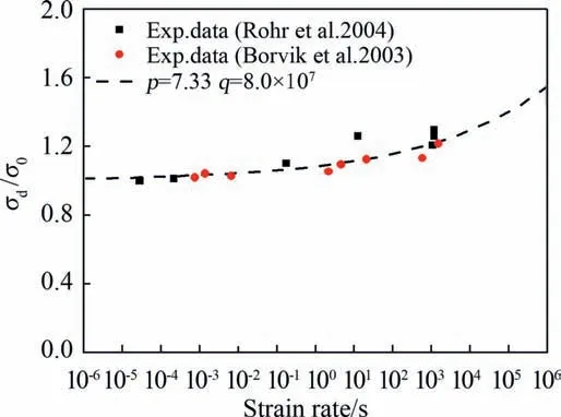
Fig. A1. Variation of σd/σ0 with strain rate.

Fig. A2. Variation of σT0/σRM0 with temperature.
- Defence Technology的其它文章
- Body armour - New materials, new systems Ian G. Crouch*
- Special materials in pyrotechnics VII: Pyrotechnics used in thermal batteries☆
- Real-time calculation of fragment velocity for cylindrical warheads
- Heavy metal free primers: Polymorphism of gadolinium and titanium in the context of GSR glass phase Felice Nunziata
- Mitigation of EDFA transient effects in variable duty cycle pulsed signals
- Ballistic impact properties of woven bamboo- woven E-glassunsaturated polyester hybrid composites

