Finite Element Modeling in Drilling of Nimonic C-263 Alloy Using Deform-3D
M. Nagaraj , A. John Presin Kumar, C. Ezilarasan and Rishab Betala
Abstract: The paper proposes a simulated 3D Finite Element Model (FEM) for drilling of Nickel based super alloy known as Nimonic C-263. The Lagrangian finite element model-based simulations were performed to determine the thrust force, temperature generation, effective stress, and effective strain. The simulations were performed according to the L27 orthogonal array. A perfect plastic work piece was assumed, and the shape is considered to be cylindrical. The spindle speed, feed rate, and point angle were considered as the input parameters. The work piece was modeled by Johnson–Cook (JC)material model and tungsten carbide (WC) was chosen as the drill bit and the body was assumed to be rigid. The demonstrative results of the thrust force and the temperature at drill bit cutting edge were substantiated with the simulated results and a percentage error was observed within 10%. Further, simulated results of effective stress and strain were also observed.
Keywords: Nimonic C-263, Thrust force, temperature, effective stress, effective strain,deform-3D, simulation.
1 Introduction
Nimonic C-263 material is a nickel-cobalt chromium-molybdenum alloy that combines proficient strength properties with beneficial fabrication characteristics in the annealed condition. However, it is very arduous to machine due to the inherent parameters such as low thermal conductivity and work hardening. This alloy is utilized prominently in manufacturing aircraft components since it has good creep and fatigue strength. The factors to be considered while carrying out machining operations are low cost and high integrity. Drilling aerospace components is a critical process and it is of paramount importance to ensure the integrity of the hole while drilling and modelling techniques are employed to estimate the machining characteristics of materials with low machinability to reduce high machining costs and poor integrity [Ezilarasan, Kumar and Velayudham(2014)]. The simulations are performed using finite element method to predict the machining parameters to reduce the expenses and cost associated with experimentation.
2 Literature review
Kolahdoozan et al. [Kolahdoozan, Azimifar and Yazdi (2014)], analyzed the impact of varying spindle speed, feed rate, and tool diameter with a constant depth of cut on tool wear while drilling Inconel 718 using a cement coated carbide tool (TiAlN). They developed a model by utilizing Minitab and FEA (DEFORM-3D, Lagrangian approach)to predict the tool wear. The predicted and experimental results were compared and reported a percentage error of 4-6%. Parida [Parida (2018)] simulated the drilling of Ti-6Al-4V using DEFORM-3D to study the effects of varying cutting speed and feed rate on torque, effective stress, effective strain, thrust, drill bit temperature. And observed that there is an increase in drill bit temperature with an increase in feed rates. Along with a reduction in the hardness of the workpiece with an increase in cutting speed due to thermal softening resulting in a low temperature drill bit. These results were validated with experiments and a good agreement between the simulated and experimental results were found. Chatterjee, Mahapatra, and Abhishek [Chatterjee, Mahapatra, and Abhishek(2016)] developed a finite element model using DEFORM-3D to predict the thrust force,torque required and circularity of the holes at the entry and exit while drilling titanium which validated the experimental results. Ucun [Ucun (2016)] compared the performances of twist and 3-flute drills while drilling Al7075-T6 alloy by varying the feed rate and cutting speed, the simulations were performed in DEFORM 3D. The thrust force, tool stress, and torque were obtained using the simulations and were compared with experimental results, and there was no significant error between them. And he also concluded that the twist drill performed better than the 3-flute drill. Gardner, and Dornfeld et al. [Gardner and Dornfeld (2006)] stated that DEFORM-3D is a robust simulation software. And it can be used to predict the machining performances during the machining operations. They also stated that the simulated results can be validated with the experimental results.
Bilgin et al. [Bilgin, Gok and Gok (2015)] developed a 3D finite element model for friction drilling in hot forming processes to determine the temperature, torque, and axial force using DEFORM 3D. The simulated results were validated with experiments and the results were found to be consistent. Gok et al. [Gok, Gok and Bilgin (2015)] performed drilling experiments with Kirschner wire after reducing the Salter-Harris type 3 epiphyseal fractures of the distal femur to measure the cutting force, thrust, heat transfer coefficient and friction coefficient to determine the temperature distribution of the drill bit. The finite element analysis were performed using DEFORM 3D. The experimental and simulated results were in accordance without any significant errors between them.Tekaut et al. [Tekaut, Demir and Seker (2018)] carried out drilling experiments on AISI H13 hot work steel by varying the cutting speed, and feed rate using uncoated, and AlCrN coated drill bits. And it was found that an increase in the feed rate resulted in an increase in the thrust force while using both the drills. Consequently, an increase in the cutting speed led to an increase in thrust force when using both the drills. But it caused an increase in the torque when drilling with uncoated drill bits and a decrease in torque when using AlCrN-coated drill bits. The simulations were performed on ANSYS workbench and the stresses were obtained, and they were in good agreement with the stresses obtained during experimental trails. Wang et al. [Wang, Zhao, Li et al. (2013)]developed a 3D finite element model to simulate and predict the cutting forces in end milling of Ti-6Al-4V. The simulated results were validated by comparing with the experimental results. Further, they suggested that, amongst the material constitutive models, the Johnson-Cook model is the most effective to model the work piece as it constitutes the effect of strain hardening, strain rate hardening, and thermal softening.
Ozel et al. [Ozel, Lianos, Soriano et al. (2011)] suggested that the 3D computational models are required to predict and analyze the machining performance of materials that are subjected to large elastic and plastic deformation. They developed a 3D model for turning of Inconel 718 using Deform 3D and ABAQUS/Explicit. The experimental values of temperature, stress, and strain were validated with FEA modelled data. Maurel-Pantel et al. [Maurel-Pantel, Fontaine, Thibaud et al. (2012)] developed a model to simulate the milling of AISI 304L stainless steel using LS-Dyna and the material is modelled based on the Johnson-Cook model. Further, they observed difficulties in the construction of accurate tool geometry, defining the mesh size for the tool, and determining the computation time. Sooa et al. [Sooa, Wall and Dewes (2006)] made a model to predict the cutting force and chip morphology during the turning of Inconel 718 using ABAQUS/Explicit software. The predicted values obtained during the simulations were validated and when compared with the experimental values an error of 6% was obtained. Patne et al. [Patne, Kumar, Karaganda et al. (2017)] developed a finite element model to predict the temperature distribution of the drilling tool when drilling titanium and the predicted values were compared with experimental results. The temperature was measured with the help of an Infra-Red camera. The experimental and predicted results were corroborated.
From the literature, it was evident that the study on finite element model to predict the machining characteristics of the Nimonic C-263 alloy during drilling operations is very limited. In this research work, finite element model is developed using Deform 3D to simulate and predict the thrust force, temperature at the cutting edge, effective stress, and strain. L27 orthogonal array was used to carry out the simulations and the experiments.
3 Experiments and results
The drilling experiments were performed on a billet of Nimonic C-263 alloy with a diameter of 70mm and thickness of 10mm. A CNC vertical machining center was used to conduct the experiments and the tool used is AlCrN coated carbide drill bit with a of diameter 6 mm.
The chemical composition of this alloy is as follows: 52.49%-Ni, 20%-Cr, 16.7%-Co,6.29%-Mo, 1.94%-Ti, 1.0%-Fe, 0.48%-Al, 0.46%-Mn, 0.19%-Si, 0.15%W, 0.07%-Cu,0.04%-Nb, 0.02%-C, 0.007%-Ta, 0.001%-S. The hardness of this alloy is 32 HRC. The drilling parameters and their levels are given in Tab. 1. Kistler piezo-electric dynamometer and pyrometer were used to measure the thrust force and temperature at the cutting edge respectively. The experimental results are given in Tab. 2.

Table 1: Drilling Parameters and their Levels
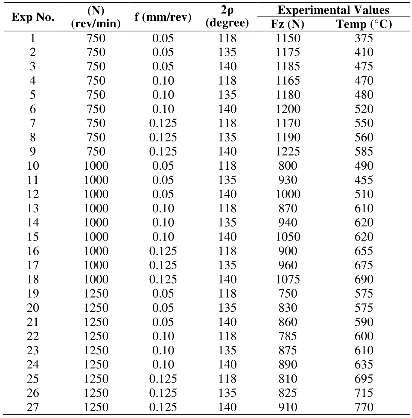
Table 2: Experimental Results
The finite element model is developed using DEFORM-3D 6.1V software to predict thrust force, the temperature at the cutting edge, effective stress, and strain. The Lagrangian approach was employed for the mesh. The work piece was considered as perfectly plastic. And the tool was considered as rigid. The DEFROM-3D software uses extended finite element machining to simulate the cutting of the work piece. And the thermo-mechanical contact algorithm is used in the DEFORM software. The material is modelled by the Johnson-Cook (JC) material model as shown in Eq. (1).

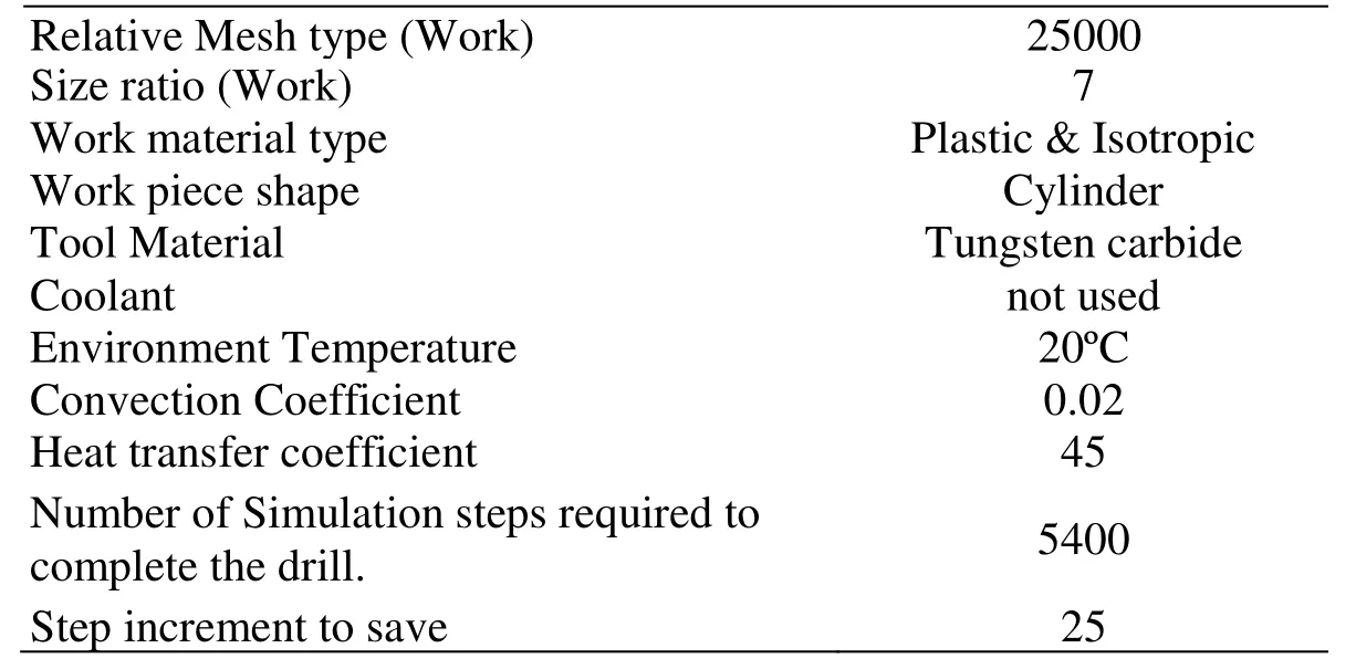
Where, σ is the flow stress, p is the plastic equivalent strain, p is the plastic strain rate, θmis the melting temperature and θRis the initial temperature, n is the hardening coefficient and m the thermal softening coefficient, coefficients A, B, and C are the yield strength(MPa), hardening modulus (MPa) and the strain rate sensitivity coefficient. The values of these parameters are: A=450 MPa, B=1700 MPa, C=0.017, n=0.65, m=1.3 and Tm=1628 K. The properties of the Nimonic C-263 material (Density-8360 kg/m3, Young’s Modulus at 20°C=224 GPa, Poisson’s ratio=0.3, Thermal Conductivity=11.72 W/mK,Heat capacity=0.461 J/g°C, Specific heat=461 J/g °C) are fed as input to define the work material. The assumptions made in this analysis are given in Tab. 3. The geometric model,mesh of the work piece, and drill bit is shown in Figs. 1(a)-1(c).
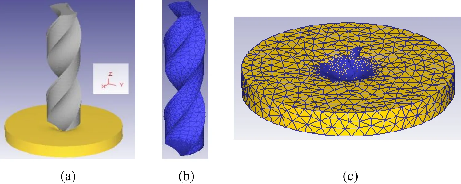
Figure 1: (a-c): (a) Geometric model, (b) Mesh of drill bit, (c) Mesh of work piece
DEFORM-3D is divided into two steps, namely pre-processor step and post processor step. In the pre-processor step, a 3D model is developed and the drilling parameters namely: spindle speed, feed rate, and point angle are considered as the machining parameters and the assumptions made in this simulation is given in Tab. 3. The second step is the post processor, in which simulation and drilling performance results are observed. The predicted results are given in Tab. 4.
The mesh size is influenced by the simulation outputs and fine mesh size of the work piece and the tool are suitable to simulate outputs without much fluctuation [Arrazola,Kortabarria, Madariaga et al. (2014)]. The relative mesh is considered for the drill bit and the work piece to develop FEA model for the prediction of the outputs by assigning the size ratio 4 and 7 for drill bit and the work piece respectively

Table 3: Assumptions of the FEA Model
?
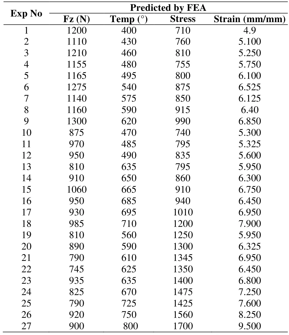
Table 4: Predicted Results by FEA
4 Results and discussion
In this research work, a DEFORM-3D finite elemental model has been developed for predicting the thrust force, temperature, and effective stress, and strain in drilling Nimonic C-263 alloy.
4.1 Simulation of thrust force
The comparison of the predicted and experimental results of the thrust force is shown in Fig. 2. It has been observed that the predicted results are closer to the experimental results. Figs. 3(a)-3(c) illustrates the output of few thrust forces generated during simulation under different drilling conditions. The relative mesh values are of 30000 and 25000 for the drill bit and the work piece respectively. It indicates synchronization between simulated and experimental results of the thrust force.
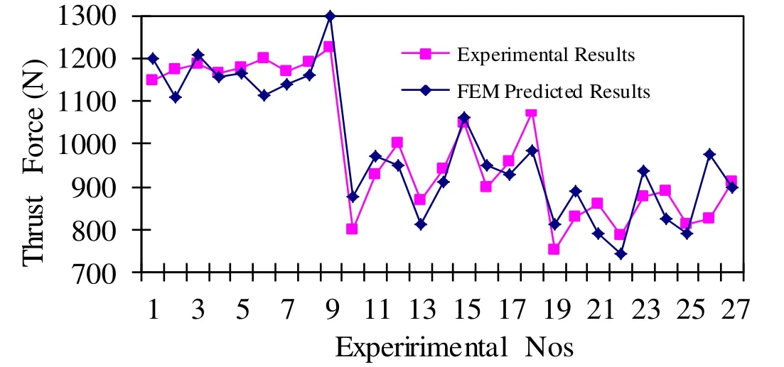
Figure 2: Comparison between FEA predicted and experimental results
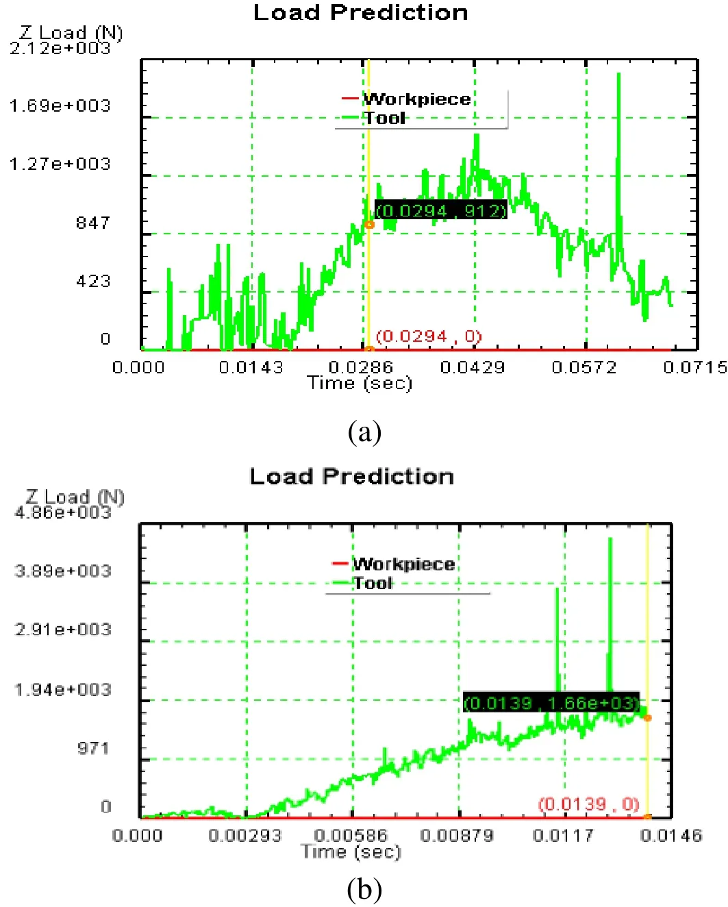
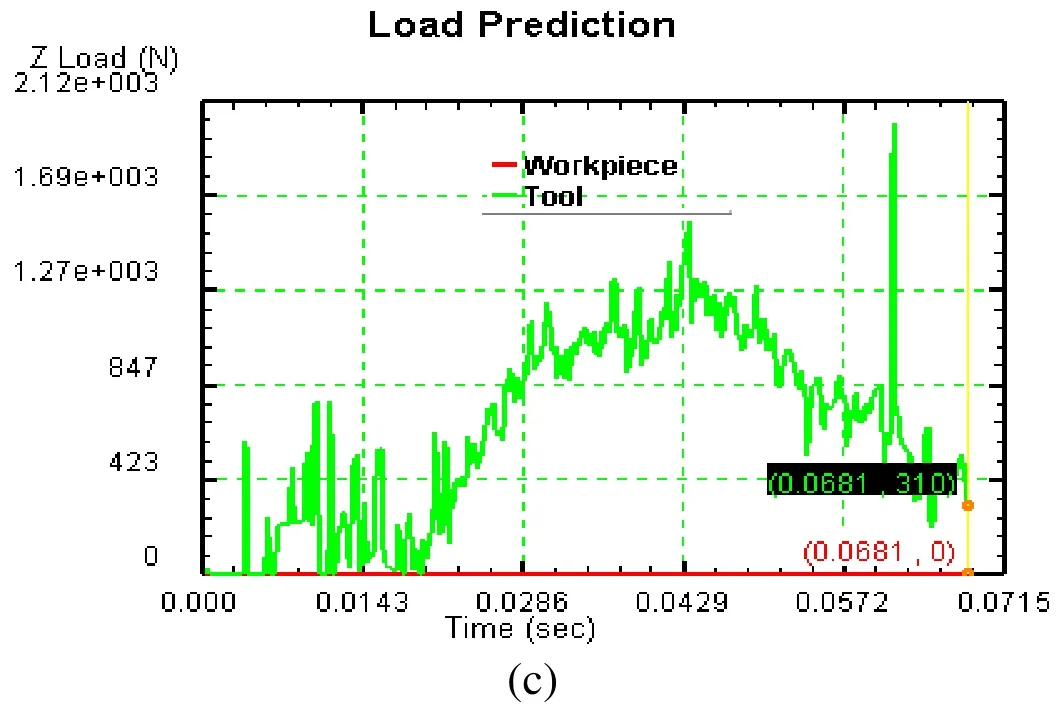
Figure 3: (a-c) FEM simulated cutting force at different conditions: (a) at N-1250 rpm, f-0.125 mm/rev, 2ρ- 140; (b) at N- 1000 rpm, f- 0.10 mm/rev, 2ρ- 135°; (c) at N- 750 rpm,f- 0.05 mm/rev, 2ρ- 118°
4.2 Simulation of temperature at drill bit cutting edge
The temperature generation affects the subsurface of the machined surface. Hence, the investigation on temperature generation at various levels of drilling parameters is important in drilling of Nimonic C-263 alloy. The effect of the feed rate at different spindle speeds on temperature distribution is shown in Fig. 4(a).
It is observed from Fig. 4(a) that the distribution of temperature in the cutting-edge increases when the level of spindle speed and feed rate increases. However, there is no significant change in the range of temperature distribution at the feed rate of 0.10 mm/rev when the spindle speed is 1250 rev/min and 1000 rev/min. The range of temperature(758°C) observed at high spindle speeds and high of feed rate is 1.76 times greater than the temperature (430°C) observed at low spindle speeds and feed rate.
The effect of spindle speed at different point angles on temperature distribution is shown in the Fig. 4(b). It is observed from Fig. 4(b), that the distribution of temperature at the cutting-edge increases when the level of spindle speed and point angle increases.
However, there is a sudden reduction in the temperature range at the spindle speed 1250 rev/min and 118°-point angle. The range of temperature (693°C) observed at high spindle speeds and high point angle is 1.42 times greater than the temperature (485°C) observed at low spindle speed and small point angle.
The effect of point angle at different feed rate on temperature distribution is shown in the Fig. 4(c). It is observed from the Fig. 4(c), that the distribution of temperature in the cutting-edge increases when the point angle and feed rate increases. The range of temperature (710°C) observed at large point angle and higher feed rate is 1.49 times greater than the temperature (476°C) observed at a smaller point angle and low feed rate.Finally, the highest temperature of 800° is achieved at the following machining conditions of 1250 rpm, 0.125 mm/rev, 140°-point angle and the lowest temperature of 400° is achieved at the following machining conditions of 750 rpm, 0.05 mm/rev, 118°-point angel are obtained. Due to the presence of γ' precipitates and complex metallic carbides at the grain boundaries in the Nimonic C-263 alloy, it prevents the easy removal materials during drilling. This results in the generation of higher temperature at the shear zone [Ezilarasan, Kumar and Velayudham (2014)].
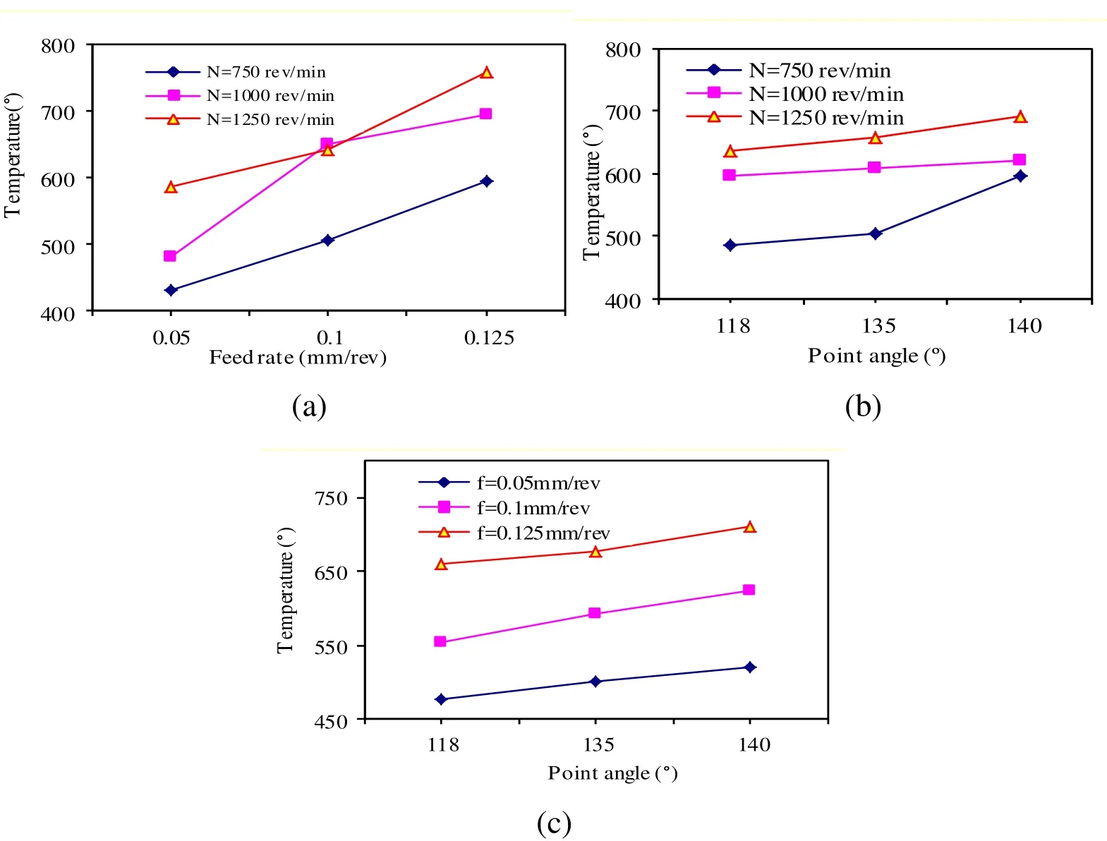
Figure 4: (a-c) Effect of machining parameters on temperature distribution: (a) Effect of feed rate on temperature distribution at different spindle speeds (b) Effect of spindle speed on temperature distribution at different point angles (c) Effect of point angle on temperature distribution at different feed rates
Further, it is also observed that the high temperature is identified at the cutting edge and the high temperature moves towards drill margin when the cutting speed increases from 750 rpm to 1250 rpm. Figs. 5(a)-5(c) shows the output of the temperature generated in the drill bit at various levels of drilling parameters and it is observed that, the generation of temperature is varied when the level of drilling parameters is varied.
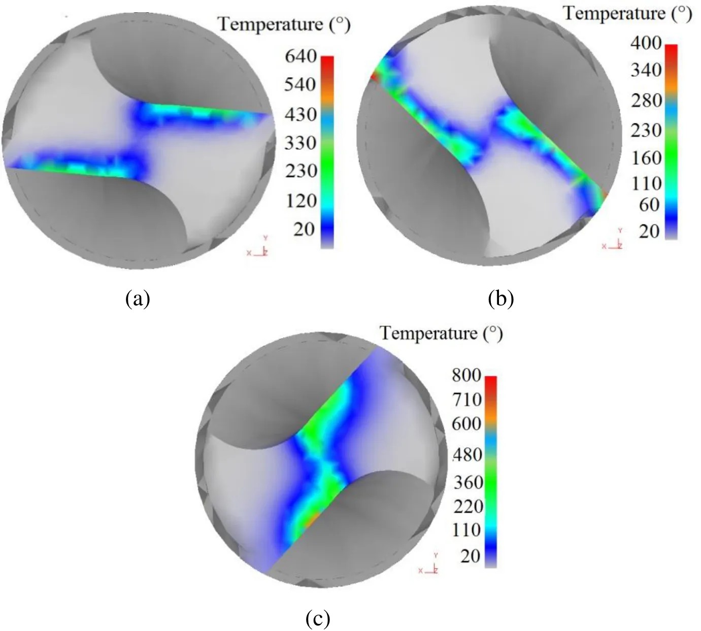
Figure 5: (a-c) Simulated temperature distribution:(a) N- 1000 rpm, f- 0.10 mm/rev and 2ρ-135°, (b) N- 750 rpm, f- 0.05 mm/rev and 2ρ- 118°, (c) N- 1250 rpm, f- 0.125 mm/rev and 2ρ-140°
4.3 Simulation of effective stress and effective strain
The shear deformation occurs during drilling as the drill bit cutting edge penetrates the work piece and its range depends on the drilling parameters. Nimonic C-263 alloy can maintain its mechanical properties at high temperatures, therefore it results in the effective stress and strain in the cutting zone to be very high. It is observed in Fig. 6 that,the effective stress and strain increases in proportion to drilling parameters such as spindle speed, feed rate and point angle. Highest stress and strain in the range of 1700 MPa and 9.5 are observed respectively at the high level of drilling parameters. The effect of cutting speed impacts is greater on the stress than on the feed rate and the point angle.The stress observed at 1250 rpm, 0.125 mm/rev, 140° (1700 MPa) is 1.416 times and 1.71 times greater than that observed at 1000 rpm, 0.125 mm/rev, 140° (1200 MPa) and at 750 rpm, 0.125 mm/rev, 140° (990 MPa). The stress observed at 1250 rpm, 0.125 mm/rev, 140° (1700 MPa) is 1.25 times and 1.15 times greater than that observed at 1250 rpm, 0.05 mm/rev, 140° (1345 MPa) and 1250 rpm,0.10 mm/rev,140° (1475 MPa). The stress observed at 1250rpm, 0.125 mm/rev, 140° (1700 MPa) is 1.19 times and 1.08 times greater than that observed at 1250 rpm, 0.125 mm/rev, 118° (1425 MPa) and at 1250 rpm,0.125 mm/rev, 135° (1560 MPa).
The range of strain increases as the drilling parameter level increases and it is also observed from Fig. 6 that the feed rate significantly affects strain when compared to its effect on cutting speed and point angle. The strain observed at 1250 rpm, 0.125 mm/rev,140° (9.5) is 1.20 times and 1.38 times greater than that observed at 1000 rpm, 0.125 mm/rev, 140° (7.9) and at 750 rpm, 0.125 mm/rev, 140° (6.85).
The strain observed at 1250 rpm, 0.125 mm/rev, 140° (9.5) is 1.36 times and 1.31 times greater than that observed at 1250 rpm, 0.05 mm/rev, 140° (6.95) and at 1250 rpm, 0.10 mm/rev, 140° (7.25). The strain observed at 1250 rpm, 0.125 mm/rev, 140° (9.5) is 1.25 times and 1.15 times greater than that observed at 1250 rpm, 0.125 mm/rev, 118° (7.6)and at 1250 rpm, 0.125 mm/rev, 135° (8.25). The observed values of effective stress and strain in the drilling of Nimonic C-263 is very well near to the values observed in the drilling of difficult to cut alloy [Kolahdoozan, Azimifar and Yazdi (2014)].

Figure 6: Distribution range of Effective stress and strain at different conditions
Figs. 7(a)-7(g) typical output of the simulated effective stress and strain distributions respectively, during the drilling of Nimonic C-263 alloy. Fig. 8 shows the percentage error observed for thrust force and temperature between experimental results and predicted values. The percentage error was observed within 10%; hence the finite element model developed can be effectively used to predict the responses
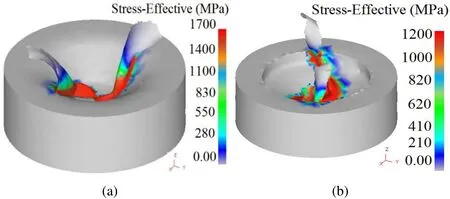
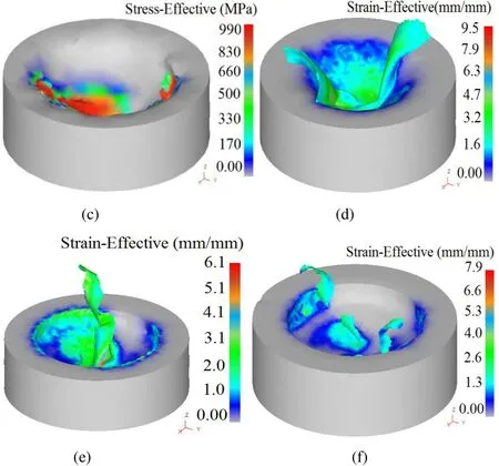
Figure 7: (a-f) Simulated Effective stress and strain distribution at different conditions:(a) stress at N-1250 rpm, f-0.125 mm/rev, 2ρ-140°; (b) stress at N-1000 rpm, f-0.125 mm/rev, 2ρ-140°; (c) stress at N-750 rpm, f-0.125 mm/rev, 2ρ-140°; (d) strain at N-1250 rpm, f-0.125 mm/rev, 2ρ-140°; (e) strain at N- 750 rpm, f-0.10 mm/rev, 2ρ-118°; (f)strain at N-1000 rpm, f-0.125 mm/rev, 2ρ-140°
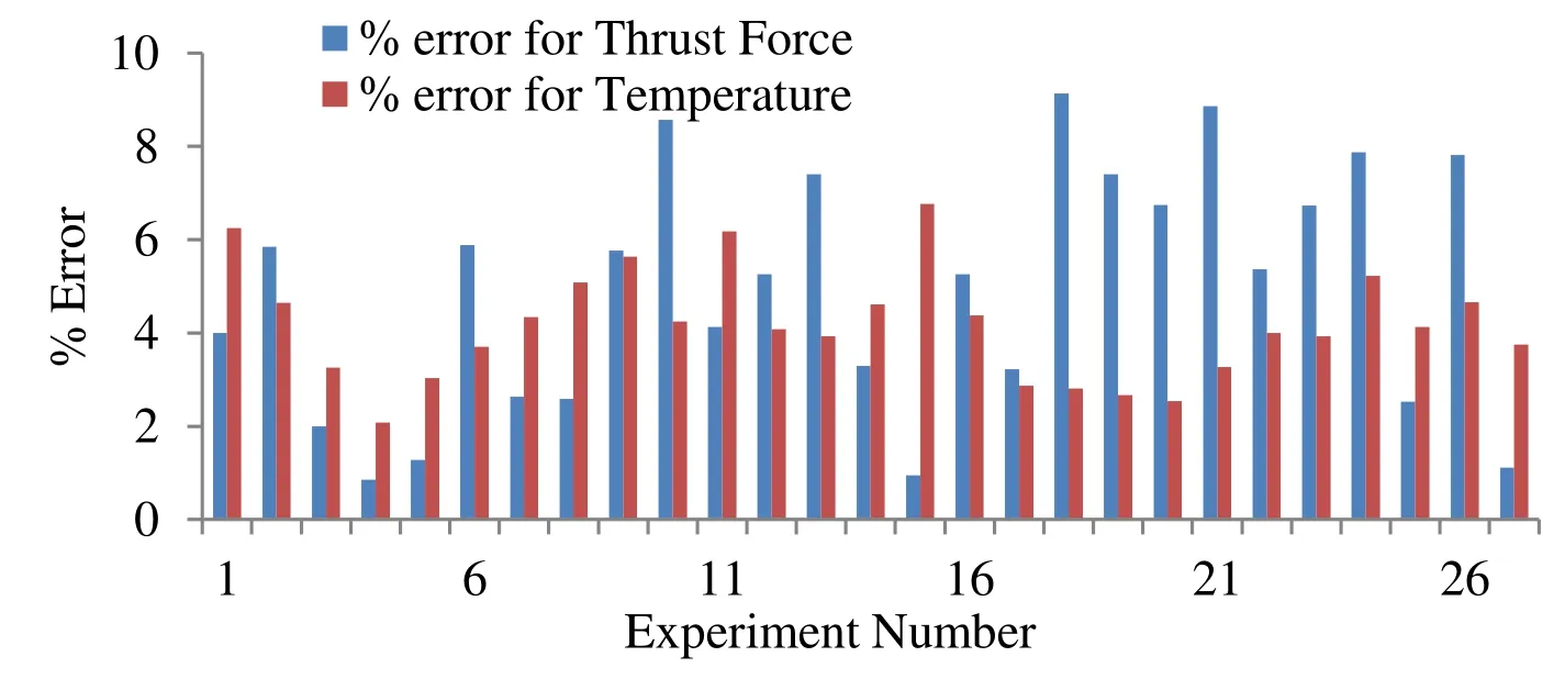
Figure 8: Percentage errors for Thrust force and Temperature between the experimental results and Predicted values
5 Conclusion
The simulated results obtained via DEFORM 3D model are listed below:
• The magnitude of the thrust force increases when the level of the feed rate and the point angle is increased; however, there is in the magnitude of the cutting force at 135°, while increasing the feed rate from 0.05 mm/rev to 0.125 mm/rev.
• Simulated thrust force varies between the range of 810N-1200N, depending on the drilling conditions. The percentage of error between the experimental and the simulated values of the thrust force was found to be within 6% in most experiments and the simulated FEA model could be effectively used to predict the thrust force during the drilling of Nimonic C-283 alloy.
• Good synchronization was observed while comparing the simulated and the experimental results of the thrust force by considering relative mesh size for drill(30,000) and work piece (25000) with the size ratios of 4 and 7 respectively. Further,the temperature, effective stress and strain were also observed for the same conditions.
• Simulated temperature at the cutting edge increases as the level of the cutting speed and the feed rate is increased, but there is no significant variation in the temperature distribution when the feed rate is 0.10 mm/rev, and the cutting speeds are 1250 rev/min and 1000 rev/min.
• A maximum stress value of 1700 MPa was attained at higher level of cutting speed,feed rate, and point angle. As the cutting speed, feed rate, and point angle are increased, strain to the range of 9.500 N/mm was observed due to larger material deformation.
Acknowledgement:The authors would like to thank to the Department of Mechanical,Hindustan Institute of Technology and Science, Chennai, India and to Velayudham, A.,Combat Vehicles Research and Development Establishment, Chennai, India.
 Computer Modeling In Engineering&Sciences2019年3期
- Computer Modeling In Engineering&Sciences的其它文章
- Analysis of Office-Teaching Comprehensive Buildings Using a Modified Seismic Performance Evaluation Method
- Quantifying Roll Feel of a Car by Using a Musculoskeletal Mathematical Model
- Dynamic Fracture Analysis for Shale Material by Peridynamic Modelling
- On Hiding Secret Information in Medium Frequency DCT Components Using Least Significant Bits Steganography
- Damped and Divergence Exact Solutions for the Duffing Equation Using Leaf Functions and Hyperbolic Leaf Functions
- Aerodynamic Characteristics Calculation and Diffusion Law Analysis of Rectangular-Chaff Clouds Under Airflow
