Dynamic Fracture Analysis for Shale Material by Peridynamic Modelling
Zhanqi Cheng, Zhenyu Wang and Zhongtao Luo
Abstract: In this work, a bond-based peridynamics (PD) model was built to analyze the dynamic fracture of shale material. Both the the convergence studies and the result of dynamic crack propagation were presented. As well-known, crack propagation,aggregation, and bifurcation play an critical role in the failure analysis of brittle materials such as shale. The dynamic crack propagation and branching analysis of shale by using the PD method were discussed. Firstly, the valid and accuracy of the PD model for the rock materials was verified by comparing with the existed numerical results. Secondly,we discussed the convergence both with uniform grid refinement (m-convergence) and decreasing the peridynamics horizon (δ-convergence). Then the shale material with two pre-crack under uniaxial compression using the present PD model were discussed, and the influence of the different angle of flaws on the behavior of crack propagation was also analyzed. The results shows that both the loading conditions and the angle of flaws can influences the crack propagation in shale.
Keywords: Peridynamics, shale, dynamic fracture, crack propagation, dynamic loads.
1 Introduction
As the heterogeneous and brittle material in nature, the crack propagation pattern and the interaction of the cracks play the key role in dynamic failure of rocks [Ravi-Chandar and Knauss (1984a, b); Zhou, Wang and Qian (2016)]. Especially under dynamic loading, the transient release of energy leads to stress re-distribution, which leads a sharp decline in rock mechanical properties and rapid crack propagation [Yang, Tang and Xia (2012)].There are many joints in rock media, which appear in bunchings and have similar orientation and mechanical properties. It can be found that the discontinuities can be any scale can exist in the grain boundaries, joint and regional faults, which significantly reduces the stiffness and strength of rocks. Hence, investigation of the crack initiation,curving and bifurcation in rock medium are both beneficial to comprehend the failure of rock material and very important for practical applications of rock engineering.
Just as well known, because cracks, joints and faults in rock materials dominate the failure process of rock materials, the simulation of dynamic fracture mechanicsm in rock materials is a difficult challenge for computational mechanics mass. In recent decades, in addition to accurately obtaining the dynamic fracture behavior of rock materials,researchers in computational mechanics have developed many methods to research the dynamic crack propagation of rock materials [Wang and Shrive (1993); Rannou, Limodin and Rthore (2010); Li and Wong (2012); Zhou, Bi and Qian (2016)]. The numerical manifold method was used by Wong et al. [Wong and Wu (2014)] to study the gradual failure in rock. They used a continuous and discontinuous combined method to conduct analysis synthesis. By using the finite difference method, a numerical model considering both material inhomogeneity and micro-defects at element scale is established by Li et al.[ Li, Konietzky and Li (2016)]. Their numerical results are in well accordance with the physical observation of fracturing process in brittle rocks. For obtaining the fracture process of rock materials, a numerical method is developed to reproduce the transition from continuum to discontinuity [Cai (2013)]. A multi-scale numerical modle was explored to study the fracture behavior of porous polygranular graphite subject to neutron damage and radiolylic oxidation, in which the relationship between the amount of microstructure of material and the crack propagation were considered [Smith, Schlangen,Flewitt et al. (2016)]. It should be noted that most numerical methods are now developed by modifying the traditional finite element method (FEM). The governing equations of these methods are partial differential equations based on classical continuum mechanics.When analyzing discontinuous problems such as cracks, the crack surface must be defined the new boundary in the renewal domain, which requires special modeling methods (such as adaptive mesh reconstruction). To find a way ot of the problem, a representative extended finite element method (XFEM), which does not require remeshing elements, is proposed to investigate crack propagation [Belytschko and Black(1999); Song, Wang and Belytschko (2008); Xu, Liu, Liu et al. (2014)]. It describes the problem of discontinuous mechanics by introducing additional functions that can reflect discontinuities into finite element functions, but XFEM is still challenged in the face of complex crack behavior, such as 3D fracture problems, multi-scale cracks, crack branching and curving and so on.
To overcome the discontinuitiy problem of displacement field in fracture problem,several kinds of mesh-free methods were built such as Smooth Particle Hydrodynamics(SPH) [Charkrabory and Shaw (2013); Raymond, Lemiale, Ibrahim et al. (2014)],Material Point Mehod (MPM) [Pandolfi(2013)], Element-free Galerkin method (EFGM)[Zi, Rabczuk and Wall (2007)] and so on. In these continuum-type methods, special standards are required to determine when to bifurate a dynamic crack and to demonstrate the crack propagation pattern [Ha and Bobaru (2011); Song, Wang and Belytschko(2008)]. As a numerical method, molecular dynamics (MD) was conducted to model and investigate the dynamic fracture problem of brittle materials [Abraham (2005); Nakano,Kalia and Vashista (1995)]. However, there are huge amounts of the molecular elements to be used to model the macro fracture for materials. Thus, MD is only used to analyze the crack initiation and propagation in brittle materials.
Alternatively, to ease inadequacies of local continuum theory, peridynamics (PD) has been proposed to model the problem of discontinuities, especial the problem of dynamic failure [Silling (2000); Silling and Askari (2005); Silling, Epton, Weckner et al. (2007)].Essentialy, PD is an integral nonlocal reconstruction for differential control equations in the continuum mechanics. This means that the discontinuity in the PD model no longer defines the displacement derivatives used in classical mechanics equations. Thus, PD can model the crack initiation and propagation without and special techniques. PD have two versions, the original formulation is bond-based, and the advanced version is state-based.However, the bond-based PD has a restriction that is the poisson’s ratio is 1/3 in plane stress state and 1/4 in 3D and plane strain state. The state-based PD is more general,where the bond interaction between points is determined by deformations of points of the entire family. Agwai et al. [Agwai, Guven and Madenci (2011)] studied the fidelity of PD theory in forcasting crack propagation through the comparative research. For multi-crack dynamic fracture problems involving complex branched joints, PD theory is considered as a suitable analytical method. By using the state-based model, the analysis of the damage growth in biomaterial specimen under thermomechanical loading is carried out by Zhang et al. [Zhang and Qiao (2018)] carried the analysis for the prediction result of of bimaterial structures under by state-based PD model. Ha et al. [Ha and Bobaru (2011)]investigated the dynamic fracture in brittle composite materials by using PD. Ren et al.[ Rabczuk and Ren (2017)] provided a double-horizon PD model to simulate dynamic brittle fracture problems. Fan et al. [Fan and Li (2017)] showed the result about soil breakage under buried blasting loads. Fan et al. [Fan, Guy and Li (2015)] simulate the soil fragementation caused by the explosion of buried explosives based on state-based peridynamics and shown the numeriacl results are agreement with the experiment. By using the PD, Gu et al. [Gu, Zhang , Huang et al. (2016)] analyzed the elastic wave spread, crack propagation, and shock fracture of concrete Brazilian discs in SPHB tests.Cheng et al. [Cheng, Zhang,Wang et al. (2015); Cheng, Liu, Zhao et al. (2018)]conducted a study about the dynamic crack propogation in FGMs.
For the rock-like material, some researchers have investigated its dynamic fracture behavior. Zhou et al. [Zhou, Wang and Qian (2016)] studied the crack propagation patterns in rock-like materials under dynamic loads based on the extended non-ordinary state-based PD. Wang et al. [Wang, Zhou and Xu (2016); Wang, Zhou and Shou (2017);Wang, Zhou, Wang et al. (2018)] conducted several PD analysis for tracking of crackpropagation in rock and brittle materials. Ni et al. [Ni, Zhu, Zhao et al. (2018)] used the irregular finite element mesh in PD model to analyze the crack problem in quasi brittle materials using. Lai et al. [Lai, Ren, Fan et al. (2015)] constrcuted the nonlinear peridynamics model of drainage and statueated geomaterials and used to simulate dynamic fracture casued by impact loads. However, the solutions to deal with the crack initiation, propagation and coalescence in layered rock materials under dynamic loads are also limited.
In this work, the bond-based PD model are employed to simulate and investigate the shale with bedding structure subjected dynamic loading. According to the elastic and fracture characteristics of the precise positions of these nodes in rock materials, a PD model for heterogeneous rock materials is constructed by using the parallel bonds between the two nodes. To study the dynamic fracture problems, the rock plates with one or several cracks are modeled under dynamic loading. The effect of material properties,time and size of dynamic loading on dynamic failure behavior are studied in the field of crack ways geometry and crack growth rate.
The organization of the paper is as follows. We briefly introduce the PD method in Section 2 and describe the bond parameters in layered rock in Section 3. In Section 4, we first conducted a study of the m-convergence and δ-convergence and provide the verification of the present model, then under the dynamic loads, we study the crack propagation pattern and the interaction of the cracks. Further, the conclusions are given in Section 5.
2 Brief review of bond-based peridynamic formulation
In the bond-based PD theory, the governing equations are provided by:

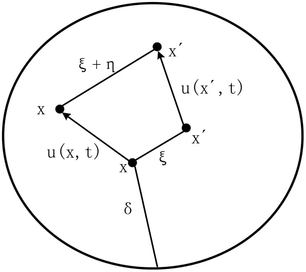
Figure 1: Illustration of peridynamic variables
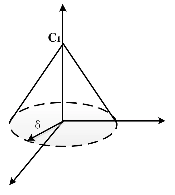
Figure 2: Conical micro-modulus functions
For a micro-elastic material, the pairing force is determined by the micro-potential function ω [Silling (2000)]:


Here, we can notice that inside the horizon region (), the pairwise force between the material pointsand, when, the material pointsanddo not have the pairwise force. In this paper, the conical micro-modulus function for plane stress state is used, and the its form is [Ha and Bobaru (2011)]:

The conical micro-modulus function is showted in Fig. 2. In the bond-based PD, a particle interacts with any particle inside its horizon only through a central potential. This assumption leads to an effective Poisson’s ratio of 1/3 in 2D and 1/4 in 3D.

Substituting Eq. (5) into Eq. (6), the critical relative elongationfor the conical micro-modulus function in 2D is:

3 The peridynamic model of shales
As we know, there are many natural tiny cracks in the rock, under the action of the load,the cracks will increase, the effective stress of the rock micro-bodies will also continue to rise, resulting in new defects continue to eventually lead to the overall decline in rock strength. Under continuous loading, we can assume that the rock micro-bodies behave macroscopically as isotropic. In addition, for shale, the bedding structure is common, so the difference of the material properties in the ply should be considered. As is shown in Fig. 3, the bond of the material is classification into two terms, the inner-layer bond and the inter-layer bond.

Figure 3: Shale material with bedding structure
3.1 The inner-layer bond
According to the PD model, any pointhas its family points, whcin the distance between point i and them is shorter than the horizon size. The bonds exist between the material pointand its family points. If both point i and all its family points are in the same layer, all the bonds between point i and its family points are called the inner-layer bond. The inner-layer bond is shown in Fig. 4. The micro-modulus functions and the critical straincan be obtained by using Eq. (5) and Eq. (7).
3.2 The interlayer bond
It can be noticed from Fig. 5(a) that the material pointhas its family points,,,,,,,.points,,,,,are located in the same ply as point,and the bonds between material point i and,,,,are the inner-layer bonds.On the contrary, the material points,,do notlocate in the same layer as point.For the material properties in different layer is different, the bonds between points,,and point i is called inter-layer bonds. Cheng et al. [Cheng, Liu, Zhao et al. (2018)]have introduced the two parallel bonds to simulate FGM. We will also use the two parallel bonds to adapt the inter-layer bonds between two points with different mechanical properties.,,and,,are the Young’s modulus,density, and fracture energy of pointsand, respectively. The two parallel bonds connect the two points are shown in Fig. 5(b). Therefore, for the concial micromodulus function, Eq. (5) and Eq. (7) can be rewrite as:


Figure 4: Classification of PD bonds in layered shale: (a) inner-layer bond; (b) the inner-layer bond between material point i and h in one layer
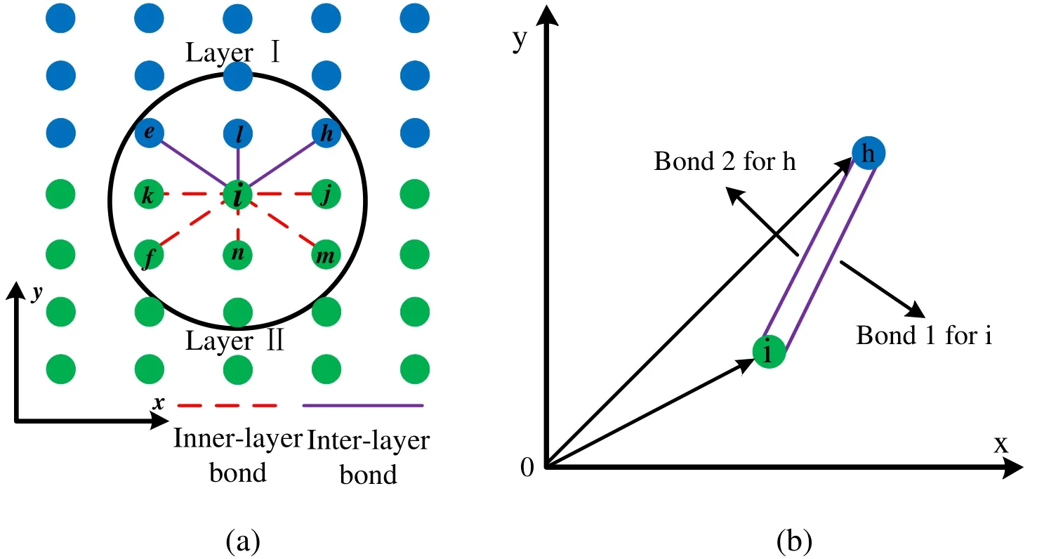
Figure 5: Classification of PD bonds in layered shale: (a) inter-layer bond; (b) the inter-layer bond between material point i and h in one layer
4 Numerical result and convergence studies
In this section, the materials specimans from the Longmaxi Formation shale of the Changxin well 1#in the southern Sichuan Basin were chosen [Wang, Dong, Li et al.(2012)]. Due to its moderate mechanical properties, high elastic modulus, brittle and hard texture, the chosen shale material is easier to form natural fractures and facilitate artificial prefabricated fractures. At the same time, the types of pores in shale are abundant, with a large number of natural micro-cracks, which is very suitable for studying the cracks and expansion in rock.
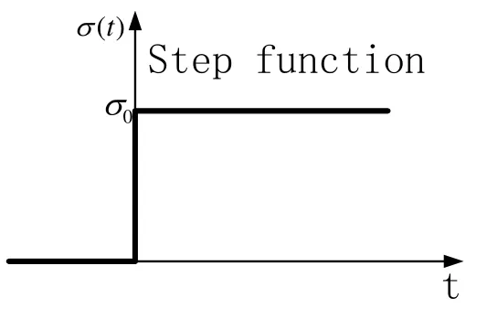
Figure 6: The vurve of load
4.1 Convergence studies of in dynamic crack propagation in shales
The PD model has been proved to be valid in the dynamic crack problem of shale material [Wang, Zhou and Xu (2016); Zhou, Wang and Qian (2016)]. In this part, the convergence of the present model is conducted by studying a edge crack in shale sample under tensile stress.

Table 1: Mechanical parameters of shale specimens [Wang, Dong and Li et al. (2012)]
4.1.1 Problem setup
In order to study the numerical convergence for PD model, an plate with a pre-notch with length of 50 mm is investigated under symmetrically dynamic tension loads on the boundary, the dimensions of the plate is 100 mm×40 mm, as shown in Fig. 7. The shale material used in this study is Longmaxi Formation shale from Sichuan, China [Wang,Dong, Li et al. (2012)] and the investigated shale specimen’s mechanical properties are listed in Tab. 1. Ravi-Chander et al. [Ravi-Chander and Knauss (1984)] had analyzed this structure of homogeneous material through experiment. σ(t) is the dynamic tensile load,as shown in Fig. 6. Beyond the loads symmetrically imposed on the boundary of the slate board, no other boundary conditions are specified.

Figure 7: Specimen geometry and boundary conditions
4.1.2 Numerical convergence
The convergence of PD model for dynamic brittle fracture has been studied be Bobaru el al. [Bobaru, Yang, Alves et al. (2009)]. In this model, we discuss two numerical convergence criteria: m-convergence and δ-convergence. In this section, The convergence is conducted through the crack propagation.
For the δ-convergence, we studied m=4 and the horizon size is 2 mm, 1.6 mm, and 1.33 mm, respectively. Under the term of the pre-crack along the x direction and σ0=8.5 MPa for PD model for the convergence study. The grid spacing determines by the each horizon size because of m is unchanged, hence, the grid spacing Δx values are 0.5 mm, 0.4 mm,and 0.33 mm, respectively. As is shown in Fig. 8, we provide the result for the PD simulations above 60 μs. It can be observed from the result that as the horizon lessens,the crack basically remain unchanged, but become clearer. It is also in agreement with the affirmation that the damage diffusion is affected by the size of horizon.
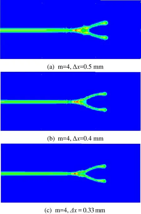
Figure 8: Crack propagation and brabching with different δ; the damage maps shown are at 60 μs
For the m-convergence study, the model and the load condition are similar with the δ-convergence, we conducted the study with fixed horizon size: δ=2 mm. We performed Δx=0.8 mm (m=2.5), Δx=0.5 mm (m=4) and Δx=0.4 mm (m=5). It can be observed from Fig. 9 that the crack path at 60 μs simulated by PD when the number of nodes in the horizon is large enough (m>4), the cracks did not change further. Furthermore, the lengths of crack propagation in Fig. 8(b) is very close to Fig. 8(c). This indicates that the crack velocity was very close to each other in the two cases. For better balance the computation cost and accuracy, we selected the horizon size δ=2 mm and m=4.

Figure 9: Crack propagation and brabching with different grids for δ=2 mm; the damage maps shown are at 60 μs
4.2 Verification of strength failure of brittle sandstone under uniaxial compression
Prior to the numerical study, the above PD model of the rock materials is verified by the strength failure of the sandstone induced by uniaxial compression, such as Yang et al.[Yang and Jing (2011)] had conducted. For this purpose, a rock sample similar to that Yang et al. [Yang and Jing (2011)] used in the experimental study was employed, and the material properties are shown in Tab. 2. Fig. 10 provided the geometry of the specimen.Consider a rock specimen with a pre-notch. The length of pre-notch is 2a and the crack angle (the angle between the crack and the direction of the horizontal direction) is β,respectively. For convenience and comparison, β=45° and 2a=25 mm are studied.

Table 2: Mechanical parameters of rock specimens
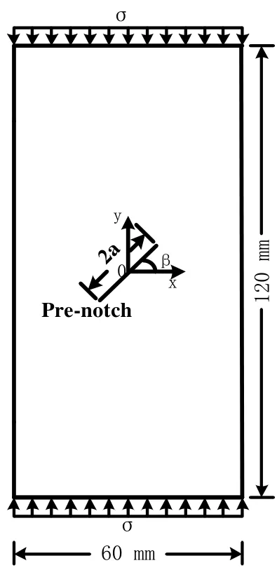
Figure 10: Specimen geometry and boundary conditions

Figure 11: Comparison of the crack paths between (a) obtained from the present model and (b) from Yang et al. [Yang and Jing (2011)]
A PD model with the horizon δ=2 mm and Δx=0.5 mm is applied to the rock specimen. Fig.11 displays the crack paths from the present model and Yang et al. [Yang and Jing (2011)]with the same condition.The results in the Fig. 11 from the PD model are very close to the experimental results by Yang et al. [Yang and Jing (2011)]. Through the above comparison,it illustrates that the PD model for the rock material is valid and effective.
4.3 Double cracks in the shale material
For shale materials, it is common that multiple cracks exists. Accordingly, it is necessary and important to study the multi-crack propagation and their interaction. In this section,we obtained a set of numerical example for shale plate under dynamic load through PD simulatioon. As we know, the shale is the bedding structure. For convenience, we consider a two-ply shale plate, which is shown in Fig. 12 [Ha, Lee and Hong (2015); Cao,Pu, Liu et al. (2015); Tang, Lin, Wong et al. (2001); Zhou, Bi and Qian (2016)]. The numerical sample with the dimensions 75 mm×150 mm and the shale plate with double cracks length of 15 mm and rock bridge length of 15 mm. β is the angle between the crack and x direction and rock bridge angle α=90°. We consider several cases for β=0°,15°, 30°, 45°, 60°, respectively, to study the affection of β on the crack propagation. The loading condition is shown in Fig. 6 and . The shale material used in this study is Longmaxi Formation shale from Sichuan, China [Wang, Dong, Li et al. (2012)] and the material properties of the shale sample are shown in Tab. 3.

Table 3: Mechanical parameters of shale specimens [Wang, Dong and Li et al. (2012)]

Figure 12: Shale specimen with two cracks: (a) geometry and boundary condition; (b)crack terms
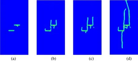
Figure 13: Snapshots of coalescence in flaw arrangements with β=0° at different instances: (a) 40 μs; (b) 54 μs; (c) 60 μs; (d) 120 μs
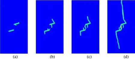
Figure 14: Snapshots of coalescence in flaw arrangements with β=15° at different instances: (a) 40 μs; (b) 54 μs; (c) 60 μs; (d) 120 μs
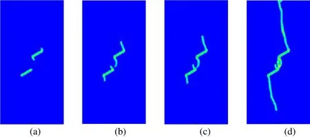
Figure 15: Snapshots of coalescence in flaw arrangements with β=30° at different instances: (a) 40 μs; (b) 54 μs; (c) 60 μs; (d) 120 μs

Figure 16: Snapshots of coalescence in flaw arrangements with β=45° at different instances: (a) 40 μs; (b) 54 μs; (c) 60 μs; (d) 120 μs
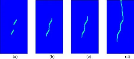
Figure 17: Snapshots of coalescence in flaw arrangements with β=60° at different instances: (a) 40 μs; (b) 54 μs; (c) 60 μs; (d) 120 μs
As can be seen from Fig. 6, the dynamic loads are suddenly applied to the boundary and remain unchanged for a subsequent period of time. This can produce stress waves in the specimen. Snapshots taken at 40 μs, 54 μs, 60 μs, 120 μs after the loads were appled for shale samples with β=0°, 15°, 30°, 45°, 60°, respectively, are presented in Figs. 13-17. It can be observed that the cracks initiation occurs at the two pre-notch tips for all the cases of β, the cracks originates from the outside tips of the cracks and propagates vertically to the top and bottom edge of the specimen, and the crack in the ply 1 propagates faster than in ply 2. Moreover, it can be found form Fig. 13 and Fig. 14 that the crack branching occurs from the inner tips of pre-crack when β=0°, 15°. Especially when β=0°, two wing cracks emanate from the tips of the pre-notchs. As β increases, the pre-existing cracks are more prone to coalesce with each other from the inner tips and propagate vertically to the top and bottom edge of the sample.
5 Conclusion
In this work, we presented a bond-based PD model for shale material with bedding structure to study its brittle dynamic fractures behavior. The dynamic crack propagation and interaction between two pre-existing cracks were discussed. We also discussed the two types of numerical convergence criteria and illustrated the the PD model is effective through the comparison with the experiment. We further studied two pre-existing cracks in shale materials with two plies subjected to dynamic uniaxial loads. The effect of the angle between the pre-notch and the horizontal direction was conducted. The numerical results indicate that the angle has a remarkable effect on the crack path and the interaction of cracks.
Acknowledgement:This work was supported by the Natural Science Foundation of China (Nos. 11472248, 51708510, 11872339) and the Natural Science Foundation of Henan Province (No. 182300410221).
 Computer Modeling In Engineering&Sciences2019年3期
- Computer Modeling In Engineering&Sciences的其它文章
- Analysis of Office-Teaching Comprehensive Buildings Using a Modified Seismic Performance Evaluation Method
- Quantifying Roll Feel of a Car by Using a Musculoskeletal Mathematical Model
- On Hiding Secret Information in Medium Frequency DCT Components Using Least Significant Bits Steganography
- Damped and Divergence Exact Solutions for the Duffing Equation Using Leaf Functions and Hyperbolic Leaf Functions
- Aerodynamic Characteristics Calculation and Diffusion Law Analysis of Rectangular-Chaff Clouds Under Airflow
- Finite Element Modeling in Drilling of Nimonic C-263 Alloy Using Deform-3D
