A Straightforward Direct Traction Boundary Integral Method for Two-Dimensional Crack Problems Simulation of Linear Elastic Materials
Chao Zhang,Chunhe Yang,Shangwei Wu ,Xiaolong Zhang, and Wen Nie
Abstract:This paper presents a direct traction boundary integral equation method(DTBIEM) for two-dimensional crack problems of materials.The traction boundary integral equation was collocated on both the external boundary and either side of the crack surfaces.The displacements and tractions were used as unknowns on the external boundary,while the relative crack opening displacement (RCOD) was chosen as unknowns on either side of crack surfaces to keep the single-domain merit.Only one side of the crack surfaces was concerned and needed to be discretized,thus the proposed method resulted in a smaller system of algebraic equations compared with the dual boundary element method (DBEM).A new set of crack-tip shape functions was constructed to represent the strain field singularity exactly,and the SIFs were evaluated by the extrapolation of the RCOD.Numerical examples for both straight and curved cracks are given to validate the accuracy and efficiency of the presented method.
Keywords:Fracture mechanics,direct traction integral method,relative crack opening displacement,stress intensity factor.
1 Introduction
The boundary element method (BEM) has been a well-established numerical technique for many engineering problems in the past decades [Brebbia,Dominquez and Tassoulas(1991)].It has certain advantages over the domain-based method,such as the finite element method (FEM).The most significant feature of the BEM is that it only requires discretization of the boundary rather than the whole domain.For the crack simulation of linear elastic materials (e.g.rock materials),stress intensity factors (SIFs) play an important role in cracked structures.The high singularity of stresses near the crack-tip has been challenging for all the previous numerical methods,even FEM [Yan,Feng,Pan et al.(2014,2013); Rabczuk,Bordas and Zi (2010)] and BEM [Cruse (2012); Aliabadi(1997)].The conventional BEM encounters difficulties as the existence of degenerated
geometries,which results in a singular system of equations.Some particular methods[Pan (1997)] have been proposed to overcome these difficulties,such as the Green’s function method [Snyder and Cruse (1975)],the multi-domain technique [Wang,Zheng,Miao et al.(2011); Miao and Wang (2005,2006)],the displacement discontinuity method(DDM) [Portela,Aliabadi and Rooke (1992)] and the dual reciprocity method (DRM)[Miao,Wang and Wang (2009a); Miao,He,Luo et al.(2012); Miao,Chen,Wang et al.(2014); Miao,Wang,Liao et al.(2009b); Ren,Zhuang and Rabczuk (2017); Ren,Zhuang,Cai et al.(2016)].For example,the Green’s function method can eliminate crack surface modelling and produces the results with an excellent accuracy.However,the method is limited to very simple crack geometries for which analytical Green’s function can be obtained [Konyukhov and Schweizerhof (2010); Rabczuk and Belytschko (2004);Rabczuk and Ren (2017)].The multi-domain technique introduces artificial boundaries to divide the problem of the domain into sub-regions,thus resulting in a large system of equations.The DDM utilizes the crack opening displacement (COD) as an unknown parameter,which can be used to calculate the stress intensity factors directly.Another promising method is the so-called dual boundary element method (DBEM).The DBEM employs both the displacement and the traction boundary integral equations.The displacement boundary integral equation is considered on the external boundary and one side of the crack surface,while the traction boundary integral equation is designated on the other crack surface to eliminate the singularity of the equation system.Singular integrals in DBEM are treated as Cauchy or Hadamard principal value integrals on piecewise smooth crack paths and can be evaluated accurately using the singularity subtraction method [Guiggiani (1998); Sur and Altiero (1988); Miao,Li,Lv et al.(2013); Lv,Miao and Zhu (2014)].In the DBEM formulation,displacements on both sides of the crack surface are considered as unknown.Thus,the resulting algebraic equations are doubled along the crack surface,which may be unnecessary for the evaluation of SIFs.Therefore,some improved single-domain BEM formulations are applied to the displacement integral equation on the external boundary.For the crack surfaces,the relative crack opening displacement (RCOD) [Ammons and Vable (1996); Chang and Mear (1996)] or the tangential derivative of the RCOD [Xie,Zhang,Huang et al.(2013)] can be chosen as unknowns therefore the traction boundary integral equation only needs to be considered on either side of crack surfaces.Recently,Mi et al.[Mi and Aliabadi (1994)] proposed a promising single-domain method named direct traction boundary integral method for three-dimensional crack problems.In this study,a direct traction boundary integral method for two-dimensional crack problems is presented as a complementary formulation.The traction boundary integral equation is applied to both the external boundary and either side of the crack surfaces.The displacements and tractions are used as unknowns on the external boundary,while the RCOD is chosen as unknowns on either side of crack surfaces to keep the single-domain merit.A new set of crack-tip shape functions is introduced to represent the strain field singularity exactly,and the SIFs are evaluated by the extrapolation of the RCOD.The outline of our study is as follows.In Section 2,the DTBIM formulations are described in detail.Section 3 explains the modelling strategy and crack-tip shape functions.The evaluation of the SIFs is illustrated in Section 4.Some numerical examples are listed in Section 5,and finally,the study ends with conclusions in Section 6.
2 Direct traction boundary integral method
Considering a finite domain Ωis surrounded by the boundary Γwith a crack as shown in Fig.1 whileΓ+and Γ-are the upper and lower crack surfaces,respectively.By differentiation of the displacement boundary integral equation,followed by the application of Hooke’s law,the traction boundary integral equation on a smooth boundary is given by:

wheretiis the traction components andni(y)denotes theithcomponent of the unit outward normal to the boundary at source point.Dijk(x,y)andSijk(x,y)are linear combinations of derivatives of the Kelvin fundamental solutions,Uij(x,y)andTij(x,y),respectively.

Figure1:A finite domain with a crack
The detailed expressions are given as:

whereris the distance between y andx.Eandvrepresent the Young’s modulus and Poisson’s ratio,respectively.niis the unit outward normal at the field pointxon the boundary andr,i=∂r/∂xi.
Based on the traction equilibrium assumed on the crack surfaces and the properties of fundamental solutions,the following formula can be obtained.

where x+and x-are points on the upper and lower crack surfaces,respectively.Substituting Eq.(4) into Eq.(1),the first term on the right side can be reduced as:

Similarly,the second term on the right side in Eq.(1) can be rewritten as:

whereuk(x+)anduk(x-)denote the displacements on the upper and lower crack surface,andΔuk(x)represents the components of RCOD,i.e.,Δuk(x) =uk(x+)-uk(x-).
Substituting Eqs.(5) and (6) into Eq.(1),the traction boundary integral equation can be rewritten as:

When the source point y is on the upper crack surface,using the relationshiptj(y) =t(y+)-t(y-) = 2t(y+),the traction boundary integral equation is modified as:

Eqs.(7) and (8) constitute the base of the direct traction boundary integral method for crack problems.When the source point is located in the integration element,the integrand will become highly singular,usually be treated as Cauchy or Hadamard principal value integrals depending on different kernels.In this study,the singular subtraction method developed by Guiggiani is utilized to evaluate the singular integrals.The details of the singularity subtraction method can be found in Miao et al.[Miao,He,Luo et al.(2012)].It should be noted that in this method only either crack surface is involved and needs to be discretized.The proposed method results in a smaller system of algebraic equations compared with the DBEM and also the proposed integral equation cannot obtain the full solution.
3 Modelling strategy
The existence of the principal value integrals in the traction boundary integral equation imposes special restrictions on the choice of elements required for the discretization of crack surfaces.These restrictions are due to the continuity requirements of the field variables for the existence of Cauchy and Hadmard principal value integrals.For convenience and simplicity,discontinuous quadratic elements as shown in Fig.2 are used to discretize both the external boundary and the either crack surface.

Figure2:Discontinuous quartic elements
The crack tip is modelled with special crack-tip elements that exactly represent the strain field singularity 1/.A detailed deduction for the crack-tip element shape functions is given as follows,which is similar to the 3D crack-tip elements proposed by Miao et al.[Miao,Li,Lv et al.(2013)].It should be pointed that the previous “quarter-point”element represents the singularity by translating the middle point of quadratic element.The proposed special crack-tip element is constructed by including the singularity into the displacement approximate.Assuming the crack tip lies at the local coordinateξ=-1,the distancer= | x (ξ)-x (-1)| is proportion toξ+ 1 in local coordinate system.The RCODΔu over the element adjacent to the crack front can be written as:

whereNi(ξ) are discontinuous quadratic shape functions.To accurately model the singularity,Eq.(9) should be modified as:

The shape functionMi(ξ) should be of the form of:

The shape functions in Eq.(11) must satisfyMi(ξj)=δij(i,j=1,2,3) for each collocation node,and a set of 3× 3linear system of equations can be obtained.By solving this system of equations,the shape functions for discontinuous crack-tip elements are obtained as:

whereλis the parametric position of collocation nodes and0<λ<1 (see Fig.2).This formulation can represent exactly the strain field singularity,because

Similarly,when the crack tip locates atξ= 1 ,the singular shape functions are given as:

4 Stress intensity factor evaluation
SIFs play an important role of characterizing fracture behavior in linear elastic fracture mechanics [Ghorashi,Valizadeh,Mohammadi et al.(2015); Areias,Msekh and Rabczuk(2016); Areias and Rabczuk (2017); Areias,Rabczuk and Dias-Da-Costa (2013)].Only the crack element on the discretized crack surface is employed to evaluate the SIF.In our implementation,the RCOD can be obtained directly from the algebraic system.Considering a local polar coordinate system centered at the crack tip,the SIFs can be expressed as follows:

whereKIandKIIare the SIFs for the deformation modes I and II,Δunand Δutare the normal and tangent components of the RCOD,respectively.

Figure3:Crack-tip boundary element
By means of a linear extrapolation from pointsP2andP3as depicted in Fig.3,the SIFs can be evaluated by

whereKP2andKP3are the SIFs evaluated by Eq.(15) at pointsPandP,respectively,23andrP2andrP3denote the distance to the crack tip from pointsP2andP3.
The proposed method is based on the crack tip element,and compared with other methods,such as the J contour integral and M domain integral,is easier to implement.
5 Numerical examples
5.1 Rectangular plate with a central slant crack
The first example considers a rectangular plate with a central slant crack in Miao et al.[Miao and Wang (2006)],as depicted in Fig.4.The width of the plate is denoted by 2wand the height by 2h.The crack has the length 2awith slant angle ofθ.The plate is loaded with a uniform tractiont,symmetrically applied at the ends.The ratio between the height and the width of the plate ish/w=2.To compare with results of the DBEM,a mesh of 30 quadratic boundary elements was used,in which 6 discontinuous elements were uniformly distributed on the either crack side.As only one crack surface was needed to be discretized,the mesh in this example was 6 elements less than that of the DBEM.

Figure4:Rectangular plate with a central slant crack (h/ w =2)

Table1:Normalized SIFs for a central slant crack in a rectangular plate(h/ w =2, θ = 4 5°) [Portela,Aliabadi and Rooke (1992)]
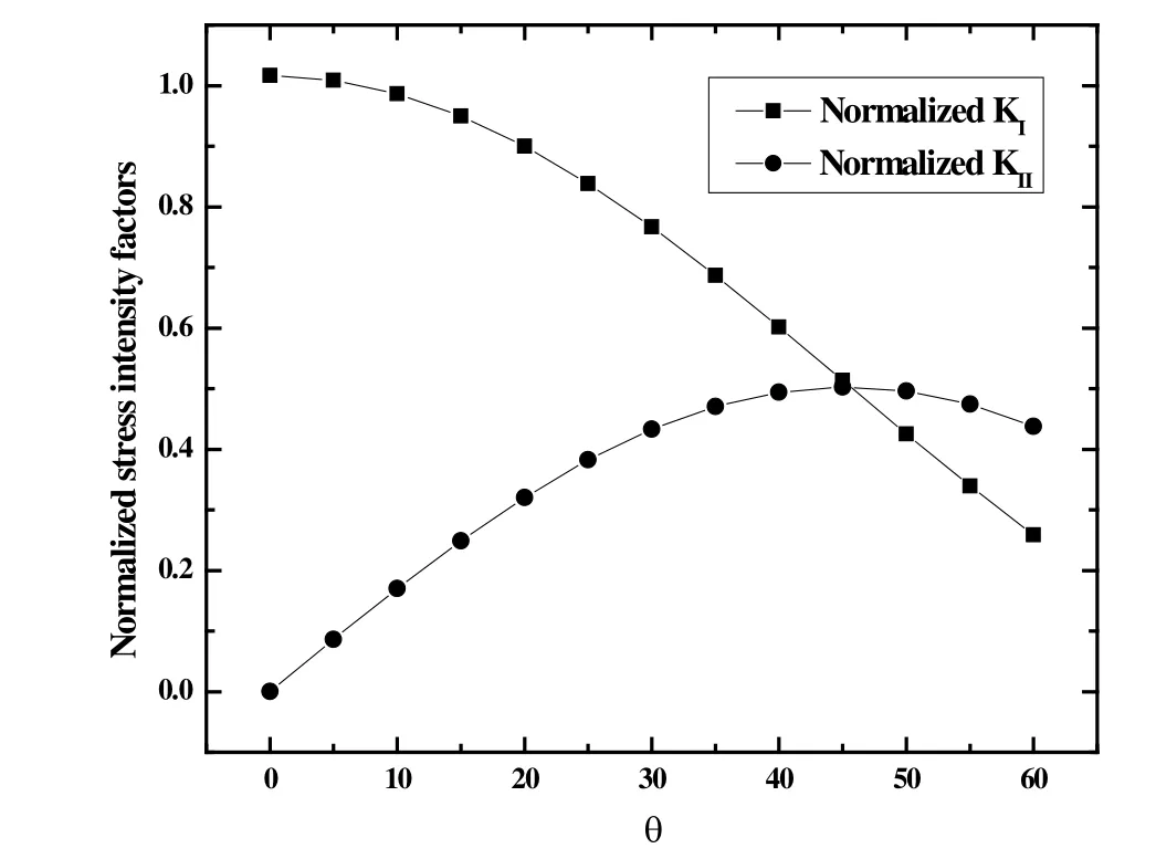
First,the angleθwas set as 45°.The accurate results at Tab.1 for this problem were published by Murakami et al.[Lv,Miao and Zhu (2014)].Five cases were considered witha/w=0.2~0.6,respectively.The results obtained are presented in Tab.1,as well as the results of the DBEM obtained by the displacement extrapolation method.The results are superior to those of the DBEM.Whena/w=0.6,the result is not accurate possibly due to the coarse mesh.The mesh refinement and convergence study were performed.It was found that if the mesh is refined around the crack,the results would be more accurate.For consistent and comparisons with the results in Portela et al.[Portela,Aliabadi and Rooke (1992)],the same mesh were employed without any refinement.Then,the graph of variation of normalized SIFs with slant angleθfrom 0° to 60° witha/w=0.2 was plotted as shown in Fig.5.From Fig.5,it can be observed thatKIdecreases along with the increase ofθand reaches the maximum value atθ= 0°.On the other hand,KIIfirstly increases and then decreases,which is in accordance with Laham et al.[Laham and Branch (1999)].

Figure5:Variation of stress intensity factors along with θ (a/ w =0.2)
5.2 Rectangular plate with a single edge crack
The second example considers a rectangular plate with a single edge crack as shown in Fig.6.The width of the plate isw,with a height of 2hand a length of the edge crackawith a slant angle ofθ.The plate is subjected to the action of a uniform tractiont,symmetrically applied at the ends.In order to compare with the results of the DBEM,a horizontal edge crack (θ= 0°) was considered withh/w=0.5.Five cases were considered,witha/w = 0.2~0.6,in which 2,3,4,5 and 6 discontinuous quadratic boundary elements were utilized to discretize the crack surface,respectively.A total of 24 discontinuous quadratic boundary elements were used to discretize the external boundary.
Table2:Normalized SIF KI/(t )for a single horizontal edge crack in a rectangular plate (θ = 0 °) [Portela,Aliabadi and Rooke (1992)]

Table2:Normalized SIF KI/(t )for a single horizontal edge crack in a rectangular plate (θ = 0 °) [Portela,Aliabadi and Rooke (1992)]
/a w Our results DBEM Reference 0.2 1.468 1.618 1.488 0.3 1.693 2.014 1.848 0.4 2.120 2.537 2.324 0.5 2.813 3.292 3.010 0.6 3.977 4.558 4.152

Figure6:Rectangular plate with a single edge crack (h/ w =0.5)
The results obtained with the proposed method and the DBEM are presented in Tab.2.In the table,the reference solutions were published by Civelek and Erdogan [Irwin,Paris and Tada (2000)].From Tab.2,it can be seen that the results for the edge crack are less accurate than those of the central crack as shown in the first example.In contrast,the proposed method results are more accurate and conservative compared with DBEM results.the graph of variation of normalized stress intensity factors with slant angleθfrom 0° to 55° witha/wequal to 0.2 was plotted as shown in Fig.7.From Fig.7,it can be observed thatKIdecreases along withθ,andKIIfirst increases and then decreases,which is similar to the central slant crack.

Figure7:Variation of stress intensity factors along with θ (a/ w =0.2)
5.3 Circular/Elliptical arc crack in infinite domain
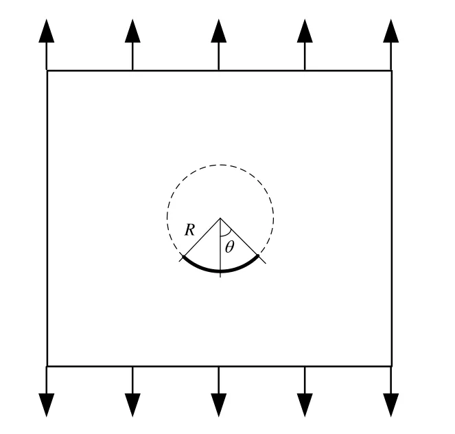
The last example considers about curved cracks.First,a circular arc crack in infinite domain is taken into account as depicted in Fig.8.The radius of the circle isR=1.0and 2θdenotes the central angle of the circular arc crack.Unit vertical traction is applied at infinity.The circular arc crack is discretized into 3 discontinuous quadratic boundary elements each 15 degrees.The exact solutions can be found in Civelek et al.[Civelek and Erdogan (1982)] as follows.Assumingθvaries from 15-75 degrees,the results obtained for the SIFs are listed in Tab.3.It can be seen from Table 3 that the results are in high agreement with the exact solutions.

Table3:SIFs for a circular arc crack in infinite domain under vertical traction
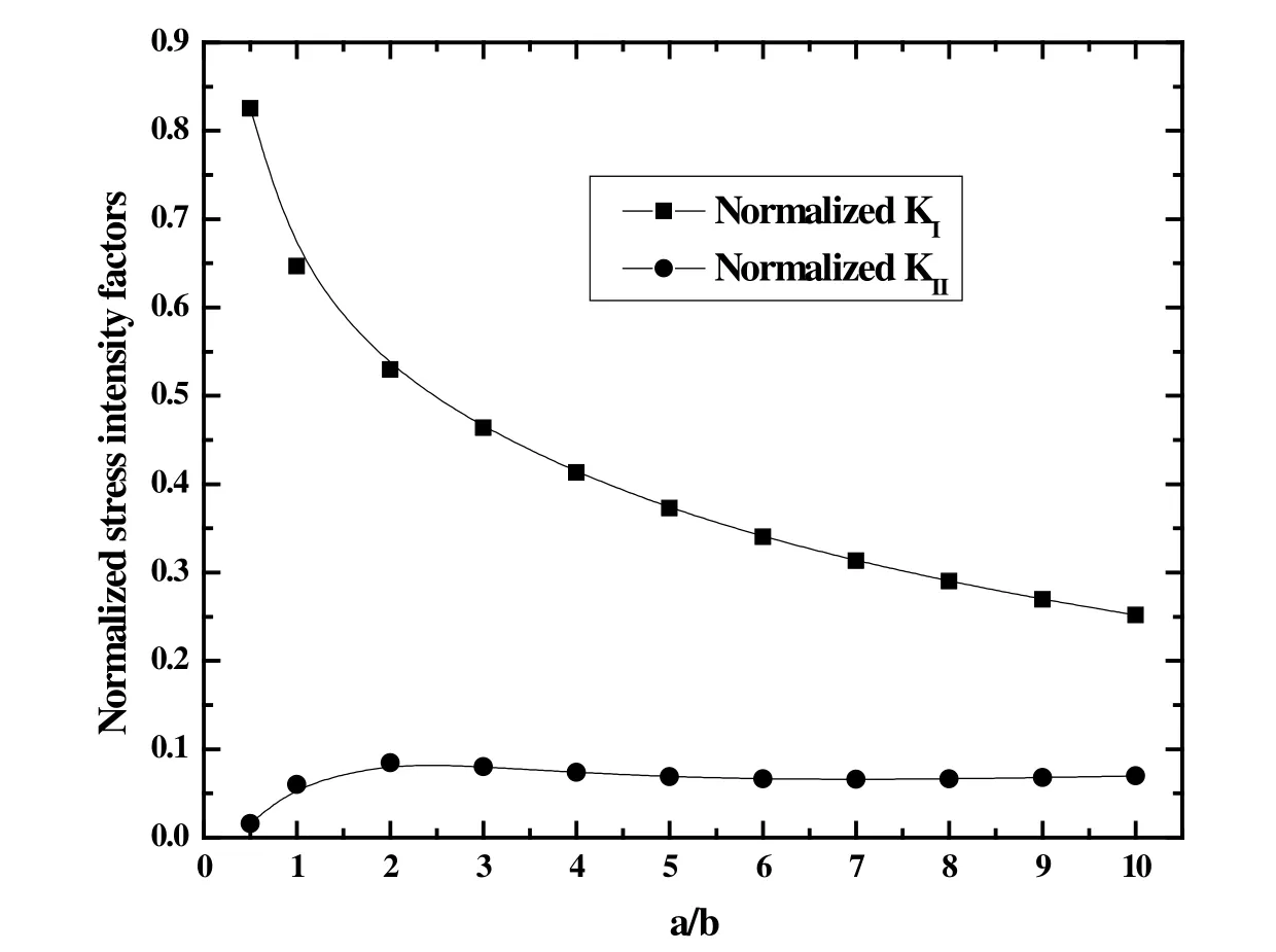
Then,a semi-elliptical arc crack in infinite domain as shown in Fig.9 is taken as another example.aandbdenote the semi-major and semi-minor axis,respectively.Unit horizontal traction is applied at infinity.Whena/bvaries from 0.5 to 10,the results for the normalized SIFs are plotted in Fig.10.Results have the same trend with the results reported by Narendran et al.[Narendran and Cleary (1984)].

Figure8:Circular arc crack in infinite domain under vertical traction


Figure9:Semi-Elliptical arc crack in infinite domain under horizontal traction

Figure10:Normalized SIFs for a semi-elliptical arc crack in infinite domain under horizontal traction
6 Conclusions
In this study,a direct traction boundary integral method for two-dimensional crack problems was presented as an alternative single-domain formulation.The traction boundary integral equation was collocated on both the external boundary and either side of the crack surfaces.The displacements and tractions were used as unknowns on the external boundary,while the RCOD was chosen as unknowns on either side of crack surfaces to keep the single-domain properly.Only one side of the crack surfaces was concerned and needed to be discretized.The proposed method resulted in a smaller system of algebraic equations compared with the DBEM.The existence of the principal integrals in the traction equation required continuity of the strain at the collocation node,thus both the external boundary and either of the crack surfaces were discretized with discontinuous quadratic boundary elements.For the crack-tips,a new set of shape functions was utilized to represent the strain field singularity exactly,and the SIFs were evaluated by the extrapolation of the RCOD.Both straight and curved cracks were taken as numerical examples,and the results of the presented method showed a lower Normalized SIFs,compared with those of the DBEM.It can be concluded that,the proposed method which is based on the crack tip element,is very straightforward in compared with other methods,such as the J contour integral and M domain integral.
In addition,applications of the BIEs to nonlinear problems need domain integrals or translating the domain integrals into boundary,which would be complicated and timeconsuming.Therefore,the BIEs is an optimal choice only for linear elastic fracture problem.Besides,the extension of applications to three dimensional will be considered in the future.Also,authors will investigate the detailed comparisons with the scaled boundary finite element method [Song,Ooi and Natarajan (2017)].
Acknowledgement:This work was supported by The National Key R & D Program of China (Grant No.2017YFC0804601),the National Natural Science Foundation of China(No.51741410),Open Research Fund of State Key Laboratory of Geomechanics and Geotechnical Engineering,Institute of Rock and Soil Mechanics,Chinese Academy of Sciences (Grant No.Z017017).
 Computers Materials&Continua2019年3期
- Computers Materials&Continua的其它文章
- Efficient Construction of B-Spline Curves with Minimal Internal Energy
- Modeling and Analysis the Effects of EMP on the Balise System
- Dynamic Trust Model Based on Service Recommendation in Big Data
- R2N:A Novel Deep Learning Architecture for Rain Removal from Single Image
- Controlled Secure Direct Communication Protocol via the Three-Qubit Partially Entangled Set of States
- Research on the Law of Garlic Price Based on Big Data
