
A method to deliver patterned electrical impulses to Schwann cells cultured on an artificial axon
2019-03-15 05:50AntonioMerolliYongMaoGregoryVoroninJosephSteeleSanjeevaMurthyJoachimKohn
中国神经再生研究(英文版) 2019年6期
Antonio Merolli , Yong Mao Gregory Voronin, Joseph A.M. Steele N. Sanjeeva Murthy Joachim Kohn
1 New Jersey Center for Biomaterials, Rutgers — The State University of New Jersey, Piscataway, NJ, USA
2 In Vivo Research Services, Rutgers — The State University of New Jersey, Piscataway, NJ, USA
Abstract Information from the brain travels back and forth along peripheral nerves in the form of electrical impulses generated by neurons and these impulses have repetitive patterns. Schwann cells in peripheral nerves receive molecular signals from axons to coordinate the process of myelination. There is evidence, however,that non-molecular signals play an important role in myelination in the form of patterned electrical impulses generated by neuronal activity. The role of patterned electrical impulses has been investigated in the literature using co-cultures of neurons and myelinating cells. The co-culturing method, however, prevents the uncoupling of the direct effect of patterned electrical impulses on myelinating cells from the indirect effect mediated by neurons. To uncouple these effects and focus on the direct response of Schwann cells,we developed an in vitro model where an electroconductive carbon fiber acts as an artificial axon. The fiber provides only the biophysical characteristics of an axon but does not contribute any molecular signaling.In our “suspended wire model”, the carbon fiber is suspended in a liquid media supported by a 3D printed scaffold. Patterned electrical impulses are generated by an Arduino 101 microcontroller. In this study, we describe the technology needed to set-up and eventually replicate this model. We also report on our initial in vitro tests where we were able to document the adherence and ensheath of human Schwann cells to the carbon fiber in the presence of patterned electrical impulses (hSCs were purchased from ScienCell Research Laboratories, Carlsbad, CA, USA; ScienCell fulfills the ethic requirements, including donor's consent). This technology will likely make feasible to investigate the response of Schwann cells to patterned electrical impulses in the future.
Key Words: Schwann cell; carbon fiber; myelination; electrical impulse; artificial axon; in vitro system; Arduino microcontroller; myelin basic protein
Introduction
Neurons located in the brain and in the spinal cord generate electrical impulses that travel along the peripheral nerves in the body. These impulses have repetitive “firing” patterns.Axons in a peripheral nerve are ensheathed and supported by Schwann cells which align themselves in a row along the axon path. The phospholipid-rich membrane of the Schwann cell wraps multiple times around axons of larger diameter. These wrappings appeared as a single thick lipid-rich sheath when observed through optical microscopy,so they were named “myelin” to define the supposed constituent substance of the sheath. Electron microscopy studies unveiled the cellular mechanism of membrane wrapping and showed how myelin sheath is produced during the process now called “myelination” (Geren and Schmitt, 1954).
The myelin basic protein (MBP) is a fundamental constituent of this wrapping. MBP keeps the cytoplasmic sides of the Schwann cell membrane close together at a distance of about 3.3 nm and it accounts for about 1/3 of the total protein content of the myelin sheath (Figure 1) (Salzer, 2015).The electrical insulating property of the myelin allows a faster conduction velocity of electrical impulses along “myelinated axons”. Smaller axons, however, are simply engulfed into a single wrap of the Schwann cell and, then, are named“unmyelinated axons”. The fundamentals of the myelination process have been defined in great detail in the past thirty years (Snaidero and Simons, 2014); this can help in trying to understand how pathological disturbances affect the process of myelination. Demyelinating diseases, however, are a growing concern for the public health; this is also because of their multifactorial nature which involves complex interactions between immune system cells, glia and neurons(Coggan et al., 2015). Myelinating cells (oligodendrocytes and Schwann cells) receive molecular signals from the axons which guide, or at least coordinate, myelination. These molecular signals are in the form of axonal membrane proteins which interact with their counterparts located in the membrane of the myelinating cell. There is evidence, however,that non-molecular signals contribute to the regulation of myelination in the form of neuronal firing of patterned electrical impulses (PEI). Brain activity has been shown to influence the pattern of connections in neural circuits during development (Buonanno and Fields, 1999). Activity-dependent myelination has been detected in oligodendrocytes and proposed as a mechanism of central nervous system plasticity (Fields et al., 1990; Stevens et al., 1998; Zalc and Fields,2000; Fields, 2014, 2015; Chang et al., 2016; Bechler et al.,2018). Electrical stimulation has been found to accelerate Wallerian degeneration and help Schwann cells to switch into migratory phenotype in vitro (Du et al., 2016). There is an interest in exploring the direct effects of patterned electrical impulses on the regulation of the myelination process.
Electrically stimulated living axons, such as those harvested from dorsal root ganglion cells, have been used to investigate on the effect of patterned electrical impulses on myelination in co-cultures of both neurons and myelinating cells in vitro(Stevens et al., 1998; Ishibashi et al., 2006; Lee et al., 2017). The co-presence of neuronal cells and myelinating cells, however,makes it difficult to un-couple direct effects of patterned electrical impulses on myelinating cells from indirect effects mediated by neurons (Althaus et al., 1984; Bullock and Rome, 1990;Howe, 2006; Gertz et al., 2010; Lee et al., 2012). The use of an artificial axon which provides only the biophysical characteristics of a living axon (namely an elongated structure of defined diameter and a periodic variation in the local electrical field)without contributing any molecular signaling would help in investigating the direct effect of patterned electrical impulses on myelinating cells. Several in vitro models have been proposed in which artificial fibers were used as surrogate axons(Althaus et al., 1984; Bullock and Rome, 1990; Howe, 2006;Gertz et al., 2010; Lee et al., 2012; Bechler et al., 2015; Merolli et al., 2017; Espinosa-Hoyos et al., 2018). None of them, however, has combined these three characteristics: 1) Schwann cell as the myelinating cell type: prior models cultured only oligodendrocytes in the absence of neurons (Althaus et al., 1984;Bullock and Rome, 1990; Howe, 2006; Gertz et al., 2010; Lee et al., 2012; Bechler et al., 2015; Espinosa-Hoyos et al., 2018). 2)a repetitive, multimodal observations of cells at the single-cell level: these repetitive observations are difficult to obtain in most of the published models where hundreds of cells are associated with hundreds of fibers (see Merolli et al., 2017 for a review); 3) the delivery of patterned electrical impulses to cells on the fiber; no experimental result has been published so far and, in any case, in very few number of papers the fibers used were electroconductive (Subramanian et al., 2012; Wu et al.,2016, 2018; Zhang et al., 2016).
Our aim was to develop a “suspended wire model”, in which the electroconductive fiber acting as an artificial axon is suspended in the culture media far from the floor of the well, so Schwann cells can interact only with it. At the same time, the Schwann cell can be exposed to periodic variation in the local electrical field produced by a microcontroller connected to the fiber. To the best of our knowledge, this is the first paper where a method to deliver patterned electrical impulses to Schwann cells cultured on a non-neuronal axon is described and where an actual PEI delivery is reported. In this study, we describe the technology needed to set-up and eventually replicate this model.
Materials and Methods
Artificial axon
An isolated electroconductive carbon fiber plays the role of the artificial axon. The carbon fiber (Fibre Glast, Brookville,OH, USA) provides an elongated structure of defined diameter (6.7 μm) with a 360-degree of surface available for the cells to wrap around. The carbon fiber diameter falls within the range of a common class of myelinated fibers in human(type II fibers) (Whitwam, 1976). Carbon fiber was chosen due to its mechanical properties, which allows the manufacturing of a linear elongated fiber that withstands stresses applied during the repetitive changes of culture media and the multiple imaging modalities.
Design of the pattern of electrical impulses
Characteristics of the pattern were completely defined via soft-ware. The voltage was set to a chosen value and the resistance was varied in the circuit to generate variable amperage. A pulsed electrical current and its pattern were shaped according to the following underlined characteristics: 1) the stimulus is constituted by a single impulse or multiple impulses; 2)this stimulus is followed by an interval, a period between two stimuli where no impulse is present; 3) the sequence of stimulus and interval can be repeated a number of times and this give us a frequency of stimulus firing and can be regarded as a tonic stimulation; 4) after a cycle of tonic stimulation, a rest pause follows where no stimulus is generated.
The parameter values of the three specific PEI used are shown in Table 1. We derived these values from a reading of the literature. However, we adopted quite arbitrarily a combination of tonic stimulation at different frequencies for 1 second, followed by a rest pause of 1 second (this combination over a prolonged time could be described as a phasic stimulation and may resemble a theta-burst stimulation pattern (Wilson et al., 2014)). Our goal was only to develop a system able to easily generate different patterns and the ones selected for this first experiment are not necessarily the best to apply.

Table 1 Parameter values of the three specific patterns electrical impulses that were selected
Design of the software
The PEI apparatus was created using an Arduino 101 microcontroller board (https: //www.adafruit.com /product/3033)which is based on the 32 bit, 32 MHz Intel Curie module and includes onboard Bluetooth Low Energy capabilities.The embedded software (termed a “sketch”), which generates the PEI and communicates over Bluetooth Low Energy,was written using the Arduino IDE (https: //www.arduino.cc /en/Main/Software). A visual programming environment,MIT App Inventor (http: //appinventor.mit.edu /explore/index-2.html), was used to develop an application for controlling the PEI apparatus wirelessly over blue tooth at low energy. Both the Arduino IDE and MIT App inventor are freely available on-line. Once programming of the Arduino 101 sketch and the PEI app were complete, validation of the output was conducted using a 1 GS/s 50 MHz 4-channel Rigol DS1054Z Digital Oscilloscope (https: //www.adafruit.com /product/2145) (Figure 2).
PEI was determined by software using five parameters: 1)half-impulse duration; 2) half-impulse number; 3) cycle period; 4) cycle number and 5) pause period. The half-impulse duration is the total time an individual either a positive or a zero signal is present on a digital pin. The half-impulse number defines the total number of positive and zero signals in a stimulus. The cycle period defines the amount of time between the beginning of the first half-impulse and the end of the last half-impulse in a stimulus. The cycle number determines the total number of stimuli before the pause. The pause period defines the time in between cycles of stimuli.After each pattern was set and transmitted over Bluetooth Low Energy from the app to the Arduino 101 boards, outputs of PEI were observed and recorded on the oscilloscope.(open source link to the software: https://github.com/lachendeKatze/PatternedElectricalImpulseProject).
Design of the scaffold device
The study of PEI requires manufacturing of a new scaffold,which supports the growth of cells on a carbon fiber while provides an electrical stimulus in vitro. The basic structure of the scaffold is that of a 3D printed poly(ε-caprolactone)frame which supports a suspended carbon fiber and its contact electrodes. An EnvisionTEC Manufacturer Series 3D-Bioplotter high-definition 3D printer was used to manufacture the support. The carbon fibers were acquired from“Fibre Glast” (Brookville, OH, USA). They have a consistent diameter of 6.7 μm, which was verified by visible light and electron microscopy analysis. This basic scaffold structure was further developed into at least eight major designs. Any design had advantages but also disadvantages and can be used for differential purposes (Figure 3).
Scaffold type A
The complex type A scaffold (Figure 3A) was ambitiously designed to exhibit several different properties: a) It has two carbon fiber wires, so one can deliver PEI and the other can be used as no-PEI control. b) It incorporates a thin scaffold suitable to support polycaprolactone (PCL) microfibers for a future application with oligodendrocytes. c) It can be fully 3D printed on an array of carbon fibers aligned and held in place by 3D printed silicone dots. d) It has a robust structure that can accommodate electrical contacts. e) It can be produced in nine copies per print (Figure 3). The thin scaffold suitable for a future use with oligodendrocytes provides a support to a network of electrospun polycaprolactone microfibers which are needed because oligodendrocytes myelinate multiple fibers at a time, in contrast with Schwann cells which myelinate a single nerve fiber. In this case, only oligodendrocytes that are in contact with the carbon fiber and the polycaprolactone fibers will be exposed to PEI.
Scaffold type B
A new design was developed that incorporated two main modifications from type A: a) It has only one carbon fiber.b) A square window of 1.5 mm × 1.5 mm suitable for microscopic observation with a full visualization at 5x magnification (Figure 3B).
Scaffold type C 3-layered
In this design, we retained the window design of type B (layer 1) and introduced a further improvement by adding the asymmetric notch to the viewing window, so the operator can check the correct positioning and sidedness under the microscope. We added the carbon fiber and two carbon-tape contacts to layer 1, then we add layer 2 to reinforce the structure. Copper wires were positioned on the sticky carbon contacts. Finally, a third layer was printed to keep the wires in place (Figure 4A-E).
Scaffold type D
The manual procedure to position the electrical contacts in type C hinders a high throughput production of such scaffolds and is likely to discourage its adoption by other research teams.
We hypothesized that the use of a 3D-printable electroconductive polymer to print contacts may streamline the process in an automated fashion. Poly(lactic acid) incorporating carbon powder was selected as the 3D printable conductive polymer. Two electroconductive stripes were printed on a scaffold similar to layer 1 of scaffold C (Figure 3D).
Scaffold type E
Scaffold type E was a smaller variant of scaffold D and was designed to fit into smaller tissue culture wells (Figure 3E).
Scaffold type F
To solve the problem of the bent of the carbon fiber, often observed in previous designs, a new design was tested in which an open geometry of the window was used (Figure 3F).
Scaffold type G
A column of conductive polymer was printed at the same height as the tissue culture well, with a central hole designed to fit connections to the ARDUINO board. Scaffold G was designed for making electrical measurements only (Figure 3G).
Scaffold type H
Scaffold H was the design proposed for a future automated production in relatively large numbers. It requires the optimization of the resistance value associated with the 3D printed contacts (Figures 3H and 4F).
Scaffold type C 2-layered
Since the scaffold development and the electronics development proceeded in parallel, as soon as we developed an effective software, as described in the Design of the software section, we selected an design from the all the scaffold types to be tested in vitro. A simplified scaffold type C with 2-layers(instead of 3-layers) seemed the most practical and was chosen for the initial tests in this study. Each face of the scaffold was sterilized under ultra violet light for 2 hours.
Design of the electronics
The electronics are built around the ARDUINO 101 board.We designed the circuitry to connect the board to the scaffolds and to control parameters such as the voltage and the amperage. A “bread-board” was used to connect up to three boards and up to three scaffolds. Resistors were put in serial in the circuit to obtain a controlled value of current amperage.
In vitro test
Human Schwann cell culture and immuno fluorescent staining
Human Schwann cells (hSC; ScienCell Research Laboratories, Carlsbad, CA, USA; ScienCell fulfills the ethic requirements, including donor's consent) have been isolated from human spinal nerve, cryopreserved and delivered frozen.The cells were thawed and then cultured in Schwann cell medium (SCM, ScienCell Research Laboratories, Carlsbad,CA, USA). To easily visualize the hSCs during in vitro testing, hSC were labeled with fluorescent CellTracker Green CMFDA Dye (Invitrogen, Carlsbad, CA, USA). hSCs were cultured to 85% confluent in the well of 6-well plate. Medium was removed and 1.5 mL of SCM base medium containing CellTracker Green CMFDA (10 μM) was added to each well and incubated at 37°C for 45 minutes. Labeled cells were trypsinized and counted. 1 × 10⁵hSCs were spun down and resuspended to 200 μL of SCM. The sterilized scaffolds were set up in the well of 12-well plate on the observation stage of microscope. 100 μL of concentrated cells were added to the carbon wire portion of the scaffold. After settling for 5-10 minutes, 1.5 mL of SCM was added to each scaffold.After observing the cells under microscope with or without PEI for a given period of time, cells on the wire were finally fixed in 4% paraformaldehyde for 30 minutes. The cells were then permeabilized by 0.5% Triton X-100 in Staining buffer(PBS + 10% bovine serum and 1% BSA) at room temperature for 1 hour. Rabbit anti-MBP antibody (ab124493; Ab-Cam, Cambridge, MA, USA) was diluted at 1:100 in Staining buffer. After incubated with primary antibodies at 4°C for overnight, the scaffolds were washed with PBS for three times. Then secondary antibody, anti-rabbit IgG-Alexa 555(Invitrogen) (1:500) and the DNA stain Hoechst Dye 33258(1:500; AnaSpec Inc. Fremont, CA, USA) in Staining buffer were added to the scaffolds and incubated at room temperature for 1 hour. After washing with PBS for three times, the scaffolds were ready for imaging analysis.
In vitro delivery of PEI to hSCs from carbon fiber
Observation and imaging were carried out on a fluorescent inverted microscope Zeiss Observer D1 (Zeiss). Images were acquired by Zeiss AxioVision software (Zeiss). Duration of PEI delivery in culture was set to 3 hours at 28°C. Images of the cells on the carbon fiber were taken every 15 min for 3 hours. Voltage was tested in two options at 32 and 75 mV.Amperage was kept to 26.5 ± 2 μA. Frequency was tested in two options at 5 and 10 Hz. The evaluation methodology has been significantly integrated and potentiated by the use of high definition laser confocal microscopy (Zeiss 780 HDCF)and helium ion Microscopy (Zeiss Orion HIM). HIM uses impinging helium ions instead of electrons as in a conventional scanning electron microscopy (SEM). In HIM the ion emission originates via field ionization from a tungsten (W)tip and is adjusted to correspond to emission from a single W atom. The extracted ions are accelerated down the column of the microscope in the same fashion as in SEM. The secondary electron yield is much higher than in SEM, giving the images a better signal-to-noise ratio. More importantly, HIM does not require a metal coating of the samples and enables the direct investigation of delicate surface features that may be obscured by the metal coating required in SEM (this is the case when cytoplasm channels rich in MBP blend into a wrapping membrane). The non-destructive sample preparation and analysis by HIM make it possible to re-image samples using other microscopy techniques.
Results
Software design
Four separate Arduino 101 boards were programmed and validated to be used for experiments. All four Arduino 101 boards demonstrated identical values for the five timing parameters required to produce the three chosen standard PEI.This indicates that all the differences in output values were below the detectable level of our oscilloscope, namely 0.01 ms. All four boards were able to have all five timing parameters changed wirelessly over Bluetooth Low Energy.
Scaffold design
Type A scaffold manifested two major problems: 1) The scaffold structure, produced from polyCaprolactone, deformed slightly after printing and minimally bent the carbon fiber.However, the slight bend prevented the carbon fiber from lying within a single focal plane along its length and became undesirable for observation under the microscope. 2) The scaffold window was too wide and the length of the carbon fiber could not be visualized in a single 5× image (low magnification), making it hard to calibrate and landmark across different microscopy platforms. Type B scaffold solved the problem of imaging. It was, however, very difficult to incorporate electrical contacts into this weak structure. Type C scaffold was very robust and its components could be 3D printed with ease in bulk. We observed that the middle layer 2 may be omitted and hence the 2-layered modification was later the design chosen for testing with cells. The major limitation of type C resides in the fact that the procedure to position the contacts was entirely manual, so a fully 3D printable type D scaffold was tested. It showed that electrical conduction along stripes was reproducible and the resistance increased with the length of the stripes. However, the scaffold shrunk after printing, resulting in excessive bending of the carbon fiber. Type E scaffold had the same shortcomings of type D. In scaffold type F, the carbon fiber was under proper tension, but placing the contacts or manipulating the scaffold transmitted excessive mechanical forces on the fiber and caused it to break.

Figure 1 Schwann cell wrapping.
Patterned electrical impulses delivery without cells
Delivery of PEI to the scaffold in air and at room temperature showed a regular and repeatable shape of the output signal that corresponded to the expected theoretical pattern(a square impulse). Delivery of PEI to the scaffold immersed in the culture media showed the appearance of a “capacitor effect” (distorsion of the square impulse). This was very limited and was not affected by the volume of the media (we tested three values for volume, namely: 1.50, 2.25, and 3.00 mL). The capacitor effect was totally reversible in less than two hours of drying of the scaffold in air.

Figure 2 The simultaneous reading of output generated by three boards shows three patterns.

Figure 3 The eight major scaffold designs.

Figure 4 Options for electric contacts.
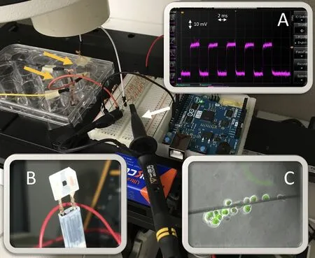
Figure 5 The experimental set-up on a fluorescence inverted microscope stage.
Patterned electrical impulses delivery to hSCs
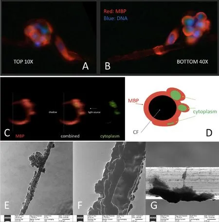
Figure 6 Wrapping on a patterned electrical impulse delivering carbon fiber.
Delivery of PEI to hSCs was attempted to investigate possible adverse effects of PEI on cells (Figure 5). Our results showed that hSCs can sustain the administration of PEI up to 3 hours (the maximum duration tested so far). hSCs have shown to start adhering to the carbon fiber and expanding their membrane on the surface of the fiber. Helium-ion scanning microscopy and high definition confocal laser microscopy showed evidence of a complete wrapping of the carbon fiber by hSCs in the presence of PEI together with the presence of cytoplasmic channels which spiral around the carbon fiber. These findings recapitulate the early steps of the myelination process. The test of two variable voltage and frequency (32 and 75 mV; 5 and 10 Hz) did not seem to significantly affect the cell behaviors on the wire in these initial experiments.
Discussion
Major results of the study
In 1984, Dr. Althaus and colleagues cultured oligodendrocytes on carbon fibers. At the end of their paper, they noted that the electroconductive property of the carbon fiber could be used to simulate the presence of an electrical-firing natural axon in vitro (Althaus et al., 1984). In 2006, Dr. Howe cultured oligodendrocytes on artificial fibers and reported about the Althaus experiment in his paper (Howe, 2006). Dr.Howe noted that the interesting feature of carbon fiber to be electroconductive let “this system has the potential for elegant studies of the role of electrical conduction in myelination”but it “was abandoned in 1984 for unknown reasons” (Howe,2006). We did not find any publications documenting any subsequent achievement of PEI delivery since 1984. It was our team at Rutgers University that delivered controlled patterned electrical impulses to hSCs cultured on a single carbon fiber on November 14 2017, more than 30 years after Althaus'proposal. Never before has any wrapping Schwann cell being subject to PEI others than that provided by natural neurons.We did not observe the detachment of cells from the fiber, a disruption in cell physiological morphology or an alteration in cell behaviors. The early two steps of adherence and wrapping that we observed are, notably, the physiological behavior of hSCs in un-myelinated nerve fibers. Therefore, this system demonstrated that at least the in vivo condition for unmyelinated nerve fibers can be recapitulated in vitro.
Microcontroller
The Arduino 101 board was chosen due to its relatively low cost, ease of programming, accurate timing properties, builtin Bluetooth Low Energy capabilities. The use of Arduino microcontrollers is reported in the literature since 2012 with increasing frequency (Schubert et al., 2013; Sheinin et al., 2015;Schultz and van Vugt, 2016; Nguyen et al., 2016; Wu et al.,2018). When considering our experimental needs, the ability to control and change impulse train parameters without disturbing the experimental apparatus was deemed highly desirable. To avoid both WiFi security and reliability concerns,Bluetooth Low Energy was chosen as the wireless protocol to do this. Bluetooth Low Energy depends only on the two radio transceivers in the transmitting and receiving devices to be operational and is limited to short distances of transmission.No other network overhead is required. The Arduino IDE contains libraries for accessing the Bluetooth Low Energy capabilities of the Arduino 101 board. Additionally, MIT App Inventor has a simple set of code blocks to access the Bluetooth Low Energy capabilities of the smartphone or tablet on which the app resides. The Arduino IDE also has a library,called CurieTimerOne, in order to access a timer present on the Intel Curie Module. One drawback to this approach is that it limits us to a single PEI impulse train pattern to each Arduino 101 board. An aim of our future software development effort will be to allow multiple, different PEI impulse patterns to be presented by a single Arduino 101.
Scaffold design
The most desired scaffold by design should be: 1) disposable,2) affordable, 3) scalable, 4) reliable. 1) Disposable: hSCs are seeded on a scaffold and observed using live-cell microscopy.They are then fixed and comprehensively imaged with several complementary modalities. At the end of the analysis the scaffold is no longer reusable. 2) Affordable: the use of gold and platinum as material for disposable electrodes seems unlikely for an affordable disposable scaffold. That is the reason why a more practical solution was investigated using copper or electroconductive poly(lactic acid). The cost of the scaffold should be kept low to encourage future widespread use.3) Scalable: initial scaffolds were produced using a manual procedure, then we gradually started to automate portions of the process by 3D printing. We aimed for a totally automated manufacturing process. 4) Reliable: reliability in the manufacturing process must guarantee that the performance of each scaffold is reproducible and superimposable.
Patterned electrical impulses delivery to cells
The electroconductive property of the carbon fiber is the most critical in this model to replicate the electrophysiological function of an axon. Our model is a true reductionist biophysical replication of the anatomy and physiology of an axon. Other authors have hypothesized that carbon fibers could be used to deliver electrical stimuli to oligodendrocytes in culture (Althaus et al., 1984; Howe, 2006), but no experimental results have ever been published neither for oligodendrocytes nor Schwann cells. Spiraling MBP-rich channels have been previously reported (Merolli et al., 2017); it may be speculated that they represent the HDCM image equivalent of the “Schmidt-Lanterman incisures” or of the “bands of Cajal”seen in transmission electron microscopy (Figure 6).
Clinical significance
Understanding of the regulation of myelination and re-myelination becomes critical in developing treatments for diseases caused by defect in myelination and re-myelination nowadays. However, we cannot study in vivo the role of potential regulatory factors of myelinating cells without the confounding effects derived from neuronal cells. Our in vitro system provides a unique opportunity to study how the external factors affect myelination of Schwann cells in the absence of neuronal factors. The clinical relevance of our research lies in the fact that the regulation of myelination process is lost in a number of diseases and, then, restoring re-myelination would be desirable in these conditions. In regard to Schwann cells, it is not easy to study them in vitro because they do not myelinate if they are cultured without axons. In vitro, Schwann cells are co-cultured with neurons which can provide them an axon to myelinate, otherwise they will simply lie flat on the culture dish floor and will not fully express their phenotype. Within in vivo models, Schwann cells and axons (and their neurons) are obviously always together. So, the study of isolated Schwann cells is extremely difficult. Our objective was to develop an in vitro system where hSCs are provided an “artificial axon” to myelinate and are exposed to patterned electrical impulses to better replicate the physiological conditions where they operate. The use of an artificial axon avoids the presence of neurons and eliminates any uncertainty if any stimulus input into the culture is acting directly on hSCs or via a neuronal-mediated mechanism. Finally, the use of hSCs, instead of animal Schwann cells, presents a much greater relevance in the light of the possible clinical translation of the research outcomes.
Conclusions
A new scaffold which used a electroconductive carbon fiber as an artificial axon was developed. An electronic control system was tested to successfully deliver patterned electrical impulses along the artificial axon. Having developed this technology, we made initial tests and delivered patterned electrical impulses to hSCs for the first time. The delivery of patterned electrical impulses did not impair the initial steps of myelination of hSCs on carbon fiber wires, so at least the in vivo condition encountered in unmyelinated nerve fibers was recapitulated in vitro.
There are some limitations in our study that will require additional effort. Currently, we are not able to use transmission electron microscopy to verify the possible formation of compact myelin on carbon fiber due to technical difficulties in sample preparation of the hSC-carbon fiber assembly. Transmission electron microscopy analysis remains our ongoing effort and promising technical solutions are being explored. Finally, the understanding of the roles of voltages and frequency on the myelination require additional detailed experiments in the future. However, our in vitro model opens a door to the investigation of the roles of patterned electrical impulses in the myelination/remyelination of Schwann cells and, hopefully, to better understand the regulation of myelination for designing treatments for diseases caused by defects in myelination.
The technology that we developed has the great potential to be reproduced, thanks to the choice of open-source hardware and software. We look forward to future studies to gain further understanding of the role of patterned electrical impulses in myelination.
Acknowledgments:The authors would like to thank Dr. Daniel Calado Martin and Prof. Prabhas V. Moghe (Department of Biomedical Engineering at Rutgers University) for the assistance with high definition confocal laser microscopy and Dr. Viaceslav Manichev, Prof. Torgny Gustaffson and Prof.Leonard Feldmann (Department of physics and Astronomy at Rutgers University) for the assistance with helium ion microscopy.
Author contributions:AM developed the “suspended wire model”, designed the study, took part in all the experimental steps, and wrote the manuscript.YM co-developed the “suspended wire model, was responsible for the cell culture methods and for the immunostaining, and co-wrote the manuscript.GV was responsible for the hardware integration, developed the software, and contributed to and revised the manuscript. JAMS was responsible for the 3D printing, and contributed to and revised the manuscript. NSM contributed in the development and testing of the electrical component, and contributed to and revised the manuscript. JK contributed in the design of the study, provided revision and criticism in the progression of the study, and contributed to and revised the manuscript. All authors approved the final version of the paper.
Conflicts of interest:There are no conflicts of interest to declare.
Financial support:Research reported in this publication was supported by the New Jersey Health Foundation under Grant #PC94-17 and by the National Institute of Biomedical Imaging And Bioengineering of the National Institutes of Health under Award Number P41EB001046 (both to JK). The content is solely the responsibility of the authors and does not necessarily represent the official views of the New Jersey Health Foundation and of the National Institutes of Health.
Institutional review board statement:hSCs were purchased from ScienCell Research Laboratories, Carlsbad, CA, USA; ScienCell fulfills the ethic requirements, including donor's consent.
Copyright license agreement:The Copyright License Agreement has been signed by all authors before publication.
Data sharing statement:Datasets analyzed during the current study are available from the corresponding author on reasonable request.
Plagiarism check:Checked twice by iThenticate.
Peer review:Externally peer reviewed.
Open access statement:This is an open access journal, and articles are distributed under the terms of the Creative Commons Attribution-NonCommercial-ShareAlike 4.0 License, which allows others to remix, tweak, and build upon the work non-commercially, as long as appropriate credit is given and the new creations are licensed under the identical terms.
Open peer reviewers:Tufan Mert, Department of Biophysics, School of Medicine, University of Cukurova, Turkey; Shan Lu, Ludwig Institute for Cancer Research, USA.
Additional file:Open peer review reports 1 and 2.

- 中国神经再生研究(英文版)的其它文章
- Busting the myth: more good than harm in transgenic cells
- Comparative study of microarray and experimental data on Schwann cells in peripheral nerve degeneration and regeneration: big data analysis
- Lessons from glaucoma: rethinking the fluid-brain barriers in common neurodegenerative disorders
- Characteristics and advantages of adenoassociated virus vector-mediated gene therapy for neurodegenerative diseases
- Gene expression changes in dorsal root ganglia following peripheral nerve injury: roles in in flammation, cell death and nociception
- Nicotinamide adenine dinucleotide phosphate oxidase activation and neuronal death after ischemic stroke