
Microstructure and wear resistance of Fe-based and Co-based coating of AISI H13
2019-02-19 05:32:58YunXiaoWangJingZhuQinghaiChenZhikaiHeBing
China Welding 2019年3期
Yun Xiao,Wang Jing,Zhu Qinghai,Chen Zhikai,2,He Bing,2
1.Jiangsu XCMG Construction Machinery Research Institute Co.Ltd,Xuzhou 221004,China;
2.State Key Laboratory of Intelligent Manufacturing of Advanced Construction Machinery,Xuzhou 221004,China
Abstract Fe-based and Co-based cladding layers were prepared on the surface of AISI H13 hot die steel by laser cladding technology.The microstructure,hardness and abrasion resistance of the two cladding layers were studied by means of optical microscope,scanning electron microscope,rockwell hardness tester,and high temperature friction and wear tester.Also,the red hardness of the cladding layers was measured,after holding the layers at 600 °C for 1 hour by muffle furnace and repeated 4 times.The rockwell hardness values of the substrate,the Fe-based and the Co-based alloy coating measured were HRC 47,HRC 52 and HRC 48,respectively.The red hardness values of the substrate and the Fe-based cladding layer were decreased,while that of the Co-based cladding layer was increased.The Co-based cladding layer has the minimal wear loss weight and friction coefficient among them.The wear mechanisms of the substrate,the Fe-based layer and the Cobased layer attribute mainly to abrasive wear,adhesion wear,and both of them,respectively.
Key words laser cladding,AISI H13,Co-based coating,red hardness,high temperature wear
0 Introduction
Since its excellent wear resistance,fatigue resistance and thermal shock resistance,the AISI H13 steel(4Cr5MoSiV1)after quenching and tempering is widely used in hot forging die,hot extrusion mould,die-casting mould,etc.However,due to the severe working environment such as high temperature and high pressure,impact load,and cold and hot fatigue,components would be damaged in a short time because of thermal wear,hot fatigue crack,deformation,and heat corrosion[1-2].Moreover,the cost of a new mould is expensive,but also the manufacturing cycle is long.The failed parts were usually repaired by machining or welding process.However,when using the machining process,the number of cycles of reuse is limited,and it is irreversible and wastes a lot of materials.When using welding repair,porosity and other problems easily occur because of the high heat input[3-4].Compared with the traditional repairs,laser cladding technology has the characteristics of high machining accuracy,small thermal deformation degree,and less follow-up processing.Hence,it has more economic benefits and application value,especially in the surface repair of large and expensive failure equipment[5].
Zhang et al[6]studied the laser cladding of Stellite X-40 cobalt-base alloy on the surface of H13 hot working die steel,and found that its wear resistance and corrosion resistance were obviously improved,and the average life of the mold was increased by more than 3 times.Li et al[7-8]studied the microstructure of Co-based alloy laser cladding on Ni-based superalloy.Ye et al[9]studied the quality of laser cladding H13 alloy coating on H13 steel surface.The parameter models for predicting cladding width in different processes were established and verified by experiments.Telasang[10]obtained an uniform microstructure by laser cladding H13 powder on H13 mold steel and by laser surface tempering for 2 hours,and the microstructure is fine.
From the perspective of cladding materials,the ironbased cladding layer with compositions similar to the H13 substrate is more resistant to cracking and wear.The cobaltbased coating has good characteristics of high temperature strength,hardness and thermal fatigue resistance,and it has been widely used in laser cladding surface strengthening of mold steel.Therefore,in this study we used H13 steel(4Cr5MoSiV1)as the substrate,and selected the Co-based layer with heat-resistant fatigue and the Fe-based layer with similar components to the substrate in the working conditions of the hot-work die steel.The microstructure,hardness,red hardness,and high temperature friction and wear properties of two cladding layers and substrates were compared and studied.

Table 1 Chemical compositions of the H13 substrate(wt%)
1 Test method
In the test,a hot-work die steel H13 in quenching and tempering state was used as the substrate.The size of the test block is 150 mm×100 mm ×40 mm,and the main alloying elements (mass fraction,%)are shown in Table 1.
The chemical compositions of the Fe powder and Co powder are listed in Table 2 and Table 3,respectively.The diode laser (Laserline LDF 6000-100,German),with the wavelength of 1.064 μm and the maximum power of 6000 W,was used for the cladding experiment.The spot diameter is 5 mm and the cladding parameters are as shown in Table 4.The whole test block was deposited by each powder in laser coaxial cladding and was deposited by vertical cross cladding between layers.The specimens were preheated to over 350 ℃ for 2 hours,and after deposition they were tempered to over 350 ℃ for 2 hours.
The microstructures of the substrate and the cladding layer,after enchanted by 4% nitric acid alcohol solution,were observed by a DMI5000M metallographic microscope and a tungsten filament scanning electronic microscope(SEM,Inspect).The hardness of the substrate and the cladding layer were tested by a rockwell hardness tester.To study the red hardness,the specimens were held at 600 ℃for 1 hour by muffle furnace,and then cooled it with air.After repeated four times,the rockwell hardness was measured.

Table 2 Chemical Compositions of the Fe-based powder(wt%)
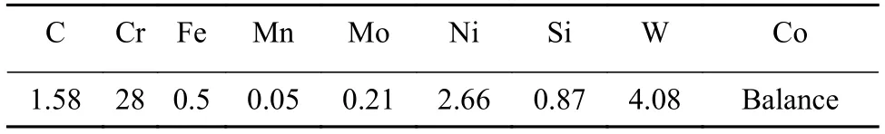
Table 3 Chemical Compositions of the Co-based powder(wt%)

Table 4 Technology parameters of the laser cladding
A HT-1000 high temperature friction and wear tester was used to study the high temperature performance of friction and wear.The dry friction was tested by the ball-plate contact way,with load of 20 N,speed of 365 r/min,friction radius of 5 mm,test time of 30 min,and test temperature of 600 ℃.The upper sample was grinded by a Si3N4ceramic ball (1590 HV0.3)with a diameter of 6 mm.The substrate and the cladding layer were respectively used as the under sample,which was a wafer (26 mm × 5 mm).The friction torque was automatically collected by the system and the friction factor can be obtained by conversion.The abrasion loss was measured by electron microbalance,and all the test data were the average values of the three measurements under the same conditions.Finally,the worn morphologies were observed by SEM.
2 Test results and analysis
2.1 Microstructure observation
Fig.1 shows the microstructure of the two cladding layers and the substrate.From Fig.1a and 1b,it can be seen that the H13 substrate is in the quenching and tempering state,and it is composed of tempered martensite,tempered troostite and residual carbide.Fig.1c and 1d show that the Fe-based layer is composed of white reticulated dendritic carbide,black intergranular carbide,tempered martensite and residual austenite.The points of A and B in Fig.1e and 1f on the primary solid solution were analyzed by energy spectrum analysis.As shown in Table 5,the points A and B were both rich in Co and Cr.The Co-based layer is composed of primary Co-Cr solid solution dendrites and eutectic structure (eutectic Co-Cr solid solution+matrix structure).The primary Co-Cr solid solution has certain directional developed dendrites,and there are multiple eutectic structures among the dendrites.

Fig.1 Microstructure of H13 substrate (a)OM image (b)SEM image;microstructure of Fe-based layer (c)OM image (d)SEM image;microstructure of Co-based layer (e)OM image (f)SEM image

Table 5 EDS analysis of the point A and point B
2.2 Rockwell hardness and red hardness
Fig.2 shows the results of the rockwell hardness and the red hardness for the cladding layer and the substrate.The average hardness value was HRC52 for the Fe-based layer,HRC 48 for the Co-based layer,and HRC 47 for the substrate.Both of the layers are harder than the substrate.

Fig.2 Hardness and red hardness of substrate and layers
The substrate and the two cladding layers were insulated by 600 ℃×1 hour×4 times.The red hardness of the substrate and the Fe-based layer were decreased to HRC 45 and HRC 49,respectively.The hardness of the Co-based layer was increased to HRC 52.It may be due to that the non-carbide forming element Co can delay the precipitation and aggregation of carbide during tempering.Moreover,the martensite containing a large amount of W and Mo has high tempering stability.Also,the dispersion of special carbides is precipitated in Co-based layer,resulting in secondary hardening effect during 500-600 ℃ tempering.
2.3 High temperature friction and wear test
The average weight loss values of the cladding layers and the substrate are shown in Fig.3.The weight loss of the substrate after 30 min was 0.004 3 g.It can be seen that the weight loss of the Co-based layer in 30 min is the least,which is 0.001 4 g.The weight loss of the Fe-based layer after 30 min was 0.002 9 g.And that of the Co-based and Fe-based layer after 30 min was 28.6%,59.2% of that of the substrate,respectively.
Fig.4 shows the curve of the friction coefficient versus time for the two cladding layers and the substrate.As can be seen,the curves are divided into two stages.The first stage is a sharp rise,which was also known as the stage of breaking-in.As the wear goes on,the contact point growth leads to a sharp increase in contact area and friction coefficient.And plastic deformation or removal of heterogeneous particles occurs on the surface of the material,and the friction surface is worn flat and enters the sTable stage.As the third body is bound to be produced in the process of wear and bear load,the friction coefficient will fluctuate slightly.It can be seen that under the high temperature of 600 ℃,The sTable friction coefficients are about 1.05,0.8 and 0.7 for the substrate,the Fe-based layer and the Co-based layer,respectively.The high temperature friction coefficient of the Co-based layer is lowest and its friction performance is best.
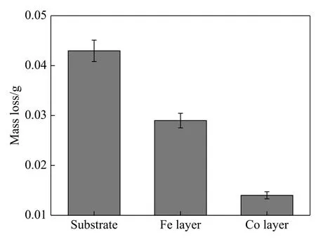
Fig.3 Worn mass loss of substrate and layers.

Fig.4 Curves of the frictional resistance coefficients for the substrate and the layers.
Because friction pair (Si3N4ceramics ball)has higher hardness,the wear losses of the substrate and the two cladding layers were large.Overall,the wear trace of the substrate and two cladding layer can be approximately regarded as the irregular circle.They were respectively divided into three regions and amplified as shown in Figure 5,6 and 7 from the inside to the outside.Fig.5a is the overall worn morphologies of the substrate,where the width of the wear ring was 1.492 mm.The wear ring widths for the Febased layer and the Co-based layer were,respectively,1.119 mm and 0.979 mm,as shown in Fig.6a and Fig.7a.The wear track width follows that:the Co-based layer < the Fe-based layer < the H13 substrate.This is consistent with the results of the friction loss weight and the friction coefficient,which also means the Co-based layer has good high temperature wear resistance.In addition,the inner ring and outer ring of three wear track have folds on the edge,indicating that a small amount of plastic deformation occurs at high temperatures.Fig.5b shows the enlarged worn morphologies for the inner side of the substrate ring wear traces.The groove had obvious plough friction surface wrinkle formation.The main wear mechanism of the coating is abrasive wear.The soft substrate is ploughed by the hard friction pair Si3N4ceramic ball,which is similar to the interaction between tool and workpiece in cutting processing.Because the substrate has a certain toughness,the concentrated compressive stress can make the friction surface produce plastic deformation.Because a large number of abrasive particles are pressed into the friction surface repeatedly and densely,the material subjected to plastic deformation flows back and forth,and finally is destroyed due to fatigue.Fig.5c shows the middle part of wear track,which is the wear serious area of whole wear trace.The furrow is obvious,which is because the Si3N4ceramic ball is easy to compress the surface of the substrate,and the substrate is the ground intensively to form the furrow grinding.As shown in Fig.5d,there was massive shedding and contact damage on the friction surface,and some tiny cracks were generated under the cutting action of abrasive particles,and the spalling caused by confluence formed pits and abrasive particles.

Fig.5 Worn morphologies of the substrate (a)The overall (b)The inside (c)The middle (d)The outside
The attachment points of Ⅰ and Ⅱ on the wear track were analyzed by energy spectrum analysis,as shown in Table 6.The points Ⅰ and Ⅱ were rich in N.It came from the friction pair of Si3N4ceramics ball.The friction pair and the mating pair suffered severe wear.It could be the adhesive material attached on the surface wear track.In addition,because of high temperature and dry process,there are a large number of oxygen elements on the surface.The wear mechanism includes oxidation wear,too.The wear mechanism of the substrate is mainly abrasive wear,accompanied by slight adhesive wear and oxidative wear.
Worn morphologies of Fe-based and Co-based layer were shown in Fig.6,Fig.7.Fig.6b,6c and 6d are the partial enlarged worn morphologies of the Fe-based layer wear track.With plastic deformation on the friction surface,a large number of abrasive grains,which are continuously rolled,and more furrows and pits appear on the surface layer-it is typical adhesive wear.Fig.6c shows the middle section of wear track,which is the wear serious area.As shown in Fig.6d,a sticking point cut and adhesion in new places,then they were cut and transferred.Such adhesion,shear,transfer and then adhesion cycle unceasingly.This constitutes adhesion wear.

Fig.6 Worn morphologies of Fe-based layer (a)The overall (b)The inside (c)The middle (d)The outside

Fig.7 Worn morphologies of the Co-based layer (a)The overall (b)The inside (c)The middle (d)The outside
The attachments of the Fe-based layer are mostly crushed,where the capture point Ⅲ was analyzed by energy spectrum analysis,as shown in Table 7.Different from the substrate,the attachment did not have a large number of nitrogen element,indicating that the wear track of the Febased layer is shallow.Because of high temperature and dry process,there are a large number of oxygen elements on the surface.The wear mechanism includes oxidation wear,too.
Fig.7b,7c and 7d are the partial enlarged worn morphology of the Co-based layer wear track.Compared with the substrate and the Fe-based layer,the Co-based layer has slight adhesion and peeling marks on the worn surface.Small abrasive grains and fine scratches on the surface of some areas on the friction surface are due to the strong antigrinding ability of the cobalt-base cladding layer at high temperature.When the Si3N4ceramic ball meets the hard phase in the cladding layer,the furrowed surface is shallow,small and even stops,so the wear loss is small.
The attachments of Co-based layer worn surface were smaller.The point Ⅳ was carried out,as shown in Table 7.Different from the substrate,attachments contained less nitrogen element.It explained the Co-based layer is crushed shallower.Different from the substrate,the attachment did not have a large number of nitrogen element,indicating that the wear track of Fe-based layer is shallow.Because of high temperature and dry process,there are a large number of oxygen elements on the surface.The main wear mechanism of Co-based layer is adhesive wear and abrasive wear,accompanied slight oxidative wear.
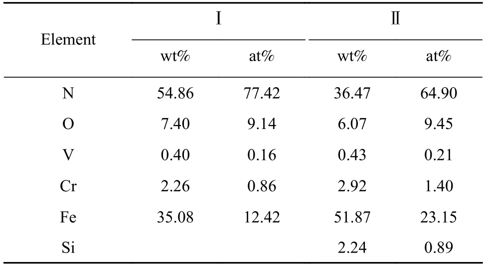
Table 6 EDS analysis of the points Ⅰand Ⅱ

Table 7 EDS analysis of the point Ⅳ
3 Conclusions
(1)The structure of substrate H13 was tempered martensite,tempered tortonite and residual carbide.The Febased cladding layer was composed of white reticulated dendrites,black intercrystalline carbides,tempered martensite,and residual austenite.The Co-based layer was composed of Co-Cr solid solution dendrites and eutectic structure.
(2)The hardness values of the H13 substrate,the Febased layer and the Co-based layer were HRC 47,HRC 52 and HRC 48,respectively.Their red hardness values were respectively HRC 45,HRC 49 and HRC 52.
(3)The worn weight loss was minimum for the Cobased layer,more for Fe-based layer,and the most for the H13 substrate.Compared with the H13 substrate and the Febased layer,the worn surface of the Co-based layer showed slight furrows.The wear mechanism of the H13 substrate attributes to abrasive wear,accompanied with slight adhesive wear and oxidation wear.The wear mechanism of the Fe-based layer attributes mainly to adhesion wear,accompanied with slight abrasive wear and oxidation wear.The wear of the Co-based layer is caused by both adhesive wear and abrasive wear,as well as by slight oxidation wear.
- China Welding的其它文章
- Thermal cycle and its influence on the microstructure of laser welded butt joint of 8 mm thick Ti-6Al-4V alloy
- Effect of the heat input on microstructure and properties of submerged arc welded joint of 08Cr19MnNi3Cu2N stainless steel
- Numerical analysis of influence of expansion joints on welding residual stress of an EGR cooler
- Filling technique for keyhole of friction stir spot welding based on the principles of resistance spot welding
- Cold cracking susceptibility of X100 pipeline steel
- Study on microstructure and properties of 590 MPa class welding wire deposited metal on hull