
Cold cracking susceptibility of X100 pipeline steel
2019-02-19 05:32:52YanChunyanJiangXinyiYuanYuanJiXiulinZhangKezhao
China Welding 2019年3期
Yan Chunyan,Jiang Xinyi,Yuan Yuan,2,Ji Xiulin,Zhang Kezhao
1.College of Mechanical and Electrical Engineering,Hohai University,Changzhou 213022,China;
2.CRRC Zhuzhou Locomotive Co.,Ltd.,Zhuzhou 412001,China
Abstract The y-groove Tekken test has been performed to evaluate the cold cracking susceptibility of X100 pipeline steel.The impact of preheating state on the microstructure,distribution of hardness,and the stress-strain state in the welded joint was analyzed.The results show that X100 pipeline steel reveals a low susceptibility to cold cracking with cracking ratios below 20%.It is found that elevated preheating temperature leads to longer cooling time in the welded specimen and ultimately results in a lower cold cracking susceptibility.Preheating temperatures of up to 100 ℃ are favorable in decreasing the cold cracking susceptibility due to a relative fine microstructure and low M-A constituent amount in coarse grained heat affected zone,a low hardenability,and low-level residual stress and strain.However,excessive preheating temperatures of 150 ℃ and 200 ℃ lead to grain coarsening,higher M-A constituent amount,higher residual stress level and increasing strain level in the Tekken specimens.Preheating temperature above 150 ℃ is not favorable for decreasing the cold cracking susceptibility of X100 steel.
Key words numerical simulation,temperature field,residual stress,strain,M-A constituent
0 Introduction
Cold cracking,also referred to as hydrogen-induced cracking (HIC),usually occurs at relative low temperatures below 150 ℃.Among the welding cracking issues for relative higher strength grade pipeline steel,cold cracking is perhaps the most significant and may happen abruptly,causing disastrous accidents if not well disposed.The occurrence of cold cracking is determined by the interaction of three factors:the hardenability of the steel,hydrogen content and distribution,and the local restraint stress and strain in the welded joint.To assess the cold-cracking sensitivity of the steels,y-groove Tekken test is frequently adopted due to its easy implementation.Węglowski et al.[3]suggested the cold-cracking tendency was decided by heat input and preheating temperature.Yi et al.[4]investigated the cold cracking in weld metal,and concluded that acicular ferrite is beneficial to prevent cold cracking and is more influential than the other factors.Chen et al.found that cold cracking could occur in pipeline steel welding when celluloid electrode was used[5].Tomić et al.[6]studied the susceptibility towards cold cracking for API 5L X80 steel,and found that different welding materials showed different sensitivity and cold cracks could form in both the HAZ and the weld metal(WM)zone.According the above review,it is concluded that there is still lack of available information on cold susceptibility of X100 steel.
The cold-cracking sensitivity of X100 steel based on Tekken test results and relative analysis of welding residual stress-strain distribution in weldments were investigated in this research.Effects of preheating temperature on cold cracks,microstructure in the weldments,hardness distribution were analyzed.Three dimensional (3D)finite element models were developed to evaluate stress distribution and investigate the effect of preheating temperature on its magnitude and distribution in the weldments.The residual strain distribution in the specimens was also analyzed.
1 Experimental
The base metal was provided as 18.4 mm thick plate and the element contents are provided in Table 1.Cellulosic welding consumables of grade E10018 with 4 mm core wire diameter were used.The scanning electron microscope(SEM)morphology of the etched X100 steel specimen is displayed in Fig.1.The microstructure of the X100 steel reveals a mainly ferritic/bainitic structure.

Table 1 Composition of investigated X100 steel(wt%)

Fig.1 X100 steel microstructure
The y-groove Tekken test was carried out with reference to AWS B4-2007.The Tekken test specimens were machined to the configuration illustrated in Fig.2.Shielded metal arc welding was adopted to conduct the welding process.The ambient temperature was 20 ℃ and the relative humidity was 45%.The welding conditions consist of 175 A welding current,24 V average arc voltage,and 16 cm/min travel speed.Five different preheating temperatures (20 ℃,60 ℃,100 ℃,150 ℃,and 200 ℃)were selected.Following welding,the specimens were left at ambient temperature for a minimum period of 48 h before examination for cracks.The test weld area of the assembly was examined for surface cracks and cross-sectional cracks,and surface cracking ratio and cross-sectional ratio were determined and recorded.
Transverse sections of the test welds under different preheating temperatures were etched with a 2 % nital reagent to reveal the microstructure using an optical microscope.For revealing the martensite-austenite (M-A)constituents in different regions of the investigated welded specimens,Le Pera’s reagent was adopted[7].The morphology and distribution of the M-A islands was studied using field emission SEM.The statistical analysis of M-A constituent area fraction was performed using the MATLAB software based on quantification from at least ten images for each investigated zone.Composition analysis of the M-A particles and the vicinal matrix metal was conducted using energy dispersive X-ray spectroscopy (EDS).Vickers hardness test was performed for all the welded specimens using 500 g load and 15 seconds loading time.
2 Finite element model
In this work,the SYSWELD finite element program was utilized to perform both the thermal and mechanical analysis.Due to the asymmetry of the welded joint across the width direction,it is required to establish the whole FE model of the joint.In general,it is best to adopt a fully identical 3D model in the numerical simulation,but these models are time consuming and costly.Therefore,simplified 3D models were adopted for welding related simulation due to the high numerical effort.Fig.3 shows the 3D mesh for the simplified y-groove Tekken test model.To decrease CPU time and storage capacity,the test weld area was modeled.
The sequentially coupled thermal-mechanical analytical method was employed to save computation time.The welding temperature field was solved first and its history was recorded.The residual stress field was solved later using the thermal data.In view of calculating precision and efficiency,a fine mesh density was selected for the deposit metal and the HAZ.The nonlinearity of material properties used in the numerical simulation was considered.In the thermal analysis,convection and radiation boundary conditions was also set and optimized.
One day three Princes, whom their father had sent abroad to travel, came to the town where Parsley lived and perceived the beautiful girl combing and plaiting her long black hair at the window

Fig.2 Shape and dimensions of the Tekken test specimen

Fig.3 FE mesh used for the analysis of Tekken test
The heat transfer analysis depends on the solution of appropriate heat equation with suitable boundary conditions.The heat input was represented by a double ellipsoid heat source to simulate the practical welding process.For representing the influence of heat input,all the parameters of the heat source were tried and confirmed based on the weld configuration and the thermal cycles.The power density distribution of the double ellipsoid heat source was determined by the following equations:

whereQis the heat input;x,y,zaccount for coordinates;ηis the heat source efficiency;qfandqraccount for heat distribution in the front and rear heat source respectively;ffandfrare distribution fractions satisfyingff+fr=2;a,b,cfandcrare shape parameters of the ellipsoids.
3 Results
3.1 Cold cracking ratio
The cracking ratio obtained is given in Table 2.It is found that the surface cracking ratio is zero for all the tested specimens.Cold cracks were inspected only on the cross sections.The cracking ratio is below 20% even without preheating and decreases with increasing preheating temperature.With a relative low preheating temperature of 60 ℃,the cracking ratio decreases to zero.Generally,if the cracking ratio of y-groove Tekken test for low-alloy steels is less than 20%,the welded structures will be safe from cold cracks[8].The results indicate adequate cold cracking resistance of the X100 steel.

Table 2 Cold cracking ratio result.
3.2 Microstructure
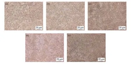
Fig.4 CGHAZ microstructures in y-groove Tekken test specimens (a)No preheating (b)60 ℃ preheating (c)100 ℃ preheating (d)150 ℃ preheating (e)200 ℃ preheating
It is commonly known that mechanical properties are mainly determined by its microstructure,and the worst toughness has been found associated to the coarse grain HAZ (CGHAZ).The microstructure of CGHAZ under different preheating temperatures is shown in Fig.4.The CGHAZ of the specimens exhibits a typical bainitic structure.Lath bainite and granular bainite appeared under no preheating condition and relatively low preheating temperature.With 150 ℃ and 200 ℃ preheating,less lath bainite and more granular bainite are observed.Moreover,the increase of preheating temperature from 150 ℃ to 200 ℃coarsens the microstructures of CGHAZ in comparison to that observed in specimen with no preheating and 60~100 ℃ preheating.Besides,higher preheating results in longer cooling timet8/3andt8/5,which means slower cooling rate.It is believed that the slower cooling rate is required to eliminate cold cracking,which is proved by the low cracking ratio of 60 ℃ and 100 ℃ preheating.
It was reported by previous researchers that M-A constituents in the microstructure seriously impaired toughness of the high-strength welded joint[9-10].Firstly,the M-A constituent amounts were calculated for CGHAZ,fusion zone(FZ),and weld metal under all preheating temperatures respectively.Then the carbon contents of M-A constituents were measured using EDS,and compared with that of the matrix.Representative morphology of M-A constituents in CGHAZ is exhibited in Fig.5.Both blocky and elongated M-A constituents can be recognized.The blocky M-A islands mostly formed at the grain boundaries,with the width of 0.5-2 μm and the length of 1-3 μm.The slender M-A constituents are mostly distributed between two ferrite laths,with the width of 0.2-0.5 μm and the length of 1~6 μm.It is reported blocky M-A constituents which are mostly located at the prior austenite grain boundaries dominantly promote impact toughness deterioration.
The effect of preheating temperature on M-A constituent amount in CGHAZ,WM and FZ is shown in Fig.6.As the preheating temperature increases,the area fractions of M-A constituent in CGHAZ,WM and FZ tend to decrease until it reaches a minimum with 100 ºC preheating.However,the area fractions of M-A constituent increase with preheating temperature in the range of 100 ºC to 200 ºC.This result indicates that larger amount of M-A constituent generates due to excessive preheating.Besides,over preheating can lead to incidence of more blocky M-A constituents in CGHAZ which in turn contributes to worse impact toughness and higher sensitivity to cold cracking.Furthermore,the microstructure coarseness can be enhanced with high preheating temperature,which further impairs the toughness.

Fig.5 SEM observation of M-A constituents in CGHAZ (a)Morphology at 2 000× (b)Morphology at 10 000×

Fig.6 Effect of preheating temperature on fraction of M-A constituent
EDS spectra of the M-A constituent and the adjacent matrix metal marked with arrow 1 and arrow 2 in Fig.5b is displayed in Fig.7.The comparison of Fig.7a and Fig.7b indicates that the compositions of the matrix metal and the M-A constituents are similar.Carbon content analysis based on EDS shows that M-A constituents are more enriched with carbon compared with the matrix metal.The difference of the two is estimated to be about 1.55 wt %.
3.3 Hardness
Traditionally,the maximum hardness value in HAZ is often used to evaluate the cold cracking sensitivity in HAZ.It is suggested that 350 HV is the maximum tolerable HAZ hardness for avoiding welding cold cracks.Hardness distribution across the welded joints under different preheating temperatures is presented in Fig.8.
It is obvious from Fig.8 that HVmaxvalue of unpreheated specimen is 270 HV.The HVmaxvalues under all five conditions are below 350 HV,which means relative low hardenability of the HAZs.However,preheated specimens exhibit lower HVmaxvalues.Under preheating condition,hardness values in both HAZ and the weld metal slightly decrease.Under preheating temperatures of 150 ℃and 200 ℃,the hardness profiles are relatively flat compared to that of the unpreheated specimen.For the preheating temperature of 200 ℃,the HVmaxvalue (240 HV)is slightly below the hardness of the base metal.

Fig.7 EDS spectra analysis result (a)Matrix (b)M-A constituent

Fig.8 Hardness distribution in the welded joints
3.4 Thermal analysis
Investigation on the temperature distribution and the thermal cycles in the welding process is of great importance,as the thermal cycle data is the basis of many other analyses like the prediction of microstructures in weld metal and HAZ,prediction of residual welding distortion and stress,and susceptibility of the weld joint for cracking,etc.The transient temperature distribution in the weldments with preheating of 100 ℃ is illustrated in Fig.9.The temperature distribution is unsteady at the initial stage of welding (t=5.3 s),and gradually becomes steady (t=15 s).Due to a preheating of 100 ℃,the peak temperature in the welding process can reach 2 488 ℃,which is much higher than the peak temperature of 1 888 ℃ with no preheating.It is also obvious that the temperature distribution in the weld piece is nonsymmetrical due to the asymmetrical Y joint shape.
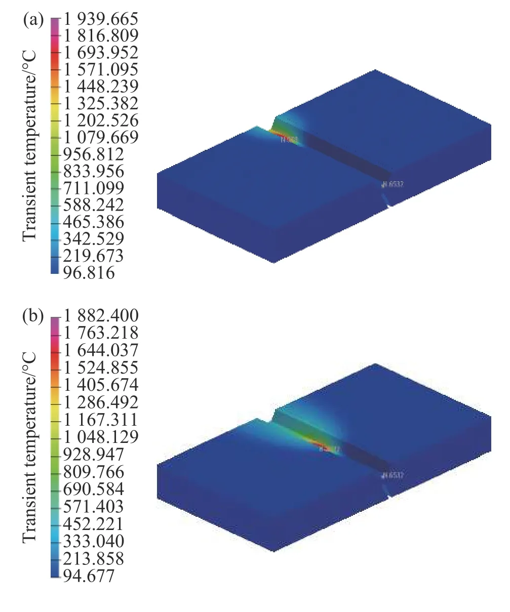
Fig.9 Transient temperature distribution (a)5.3 s (b)15.0 s
Fig.10a and Fig.10b show the thermal cycles at the locations which are 3.0 mm from fusion-line in 1/2 weld thickness on both sides of the weld,respectively.The overall temperature is high at a high preheating temperature.

Fig.10 Simulated thermal histories in the weld (a)nonsymmetrical side (b)symmetrical side
The cooling timest8/5andt8/3of a node in HAZ were plotted against preheating temperature,as shown in Fig.11.With higher preheating temperature,the cooling rates in both HAZ and WM decrease,changing the HAZ microstructure accordingly.Besides,a high preheating temperature enlarges the austenite formation and may lead to in grain coarsening in the HAZ.
3.5 Mechanical analysis

Fig.11 Impact of preheating temperature on cooling time

Fig.12 Distribution of Von Mises stress with different preheating conditions (a)No preheating (b)100 ℃ preheating(c)150 ℃ preheating

Fig.13 Distribution of longitudinal residual stress with different preheat conditions (a)No preheating (b)100 ℃preheating (c)150 ℃ preheating
The residual stress distribution in the weldments under different preheating conditions is provided in Fig.12 to Fig.14.It is apparent that the residual stress distribution in the entire joint is clearly uneven due to the asymmetrical Y joint shape.Tensile stress occurs in both WM and HAZ close to fusion boundary while compressive stress occurs in base metal remote from the weld center.It can be seen from the figures that the stress levels of the stop positions of welding are higher than that of the start positions.
The maximum magnitudes of two stress components and the equivalent stress were described in Fig.15.The magnitude of longitudinal stress is higher than that of the transverse stress.Orientation of maximum principal stress is close to the weld direction.It is therefore believed that the main crack propagates along the transverse weld direction.This agrees with the experimental findings of the present work.As one can see,Von Mises stress magnitude decreases with preheating temperature until the preheating temperature reaches 100 ℃,and then increases with the preheating temperature.The longitudinal residual stress magnitude decreases with the preheating temperature until 150 ℃ and then increases with the preheating temperature.

Fig.14 Distribution of transverse residual stress with different preheat conditions (a)No preheating (b)100 ℃ preheating (c)150 ℃ preheating
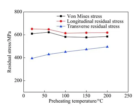
Fig.15 Variation of maximum residual stresses with preheating temperature

Fig.16 Calculated distribution of equivalent strain
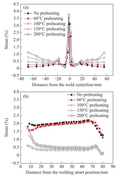
Fig.17 Effect of preheating temperature on equivalent strain distribution (a)Width direction (b)Length direction
The calculated equivalent strain for non-preheated specimen is shown in Fig.16.It can be seen that the highest strain appeared at the symmetrical side of the weld root,indicating high possibility of cracking occurrence in this position.The variation of strain distribution under different preheating conditions is shown in Fig.17.Under a relative low preheating temperature of 60 ℃,the distribution of strain in the welded specimen becomes more even and the residual strain level is depressed.Yet,under a higher preheating temperature of 150 ℃,the residual strain level ascends and strain localization adjacent to WM is developed.This implies that the relationship between the preheating temperature and mechanical properties is not monotonous.Up to 100 ℃,preheating is beneficial and a preheating temperature above 150 ℃ is not appropriate for cracking prevention.
4 Conclusions
In the present paper the cold cracking susceptibility of HAZ in X100 pipeline steel was evaluated using the Tekken test.Effects of preheating on distribution of microstructures,the hardness distribution,the welding temperature histories and the stress-strain state were discussed.The useful conclusions are summarized as below.
(1)Experimental Tekken test results show that the susceptibility of investigated X100 steel to cold cracking is low and the cracking ratio is significantly decreased with preheating.
(2)The microstructures in the welded joints are significantly influenced by the preheating temperature.Preheating at above 150 ℃ leads to grain coarsening and increase in fraction of M-A constituents.
(3)Preheating of 60 ℃ and 100 ℃ results in a reduction in the magnitude of residual stress and strain level.
However,preheating above 150 °C is not appropriate for reducing the cold cracking susceptibility of X100 steel due to increasing level of residual stress and strain.
- China Welding的其它文章
- Thermal cycle and its influence on the microstructure of laser welded butt joint of 8 mm thick Ti-6Al-4V alloy
- Microstructure and wear resistance of Fe-based and Co-based coating of AISI H13
- Effect of the heat input on microstructure and properties of submerged arc welded joint of 08Cr19MnNi3Cu2N stainless steel
- Numerical analysis of influence of expansion joints on welding residual stress of an EGR cooler
- Filling technique for keyhole of friction stir spot welding based on the principles of resistance spot welding
- Study on microstructure and properties of 590 MPa class welding wire deposited metal on hull