
自动驾驶车辆E/E架构的安全因素
2019-02-14 06:27:14高仕宁周时莹龚宝泉
汽车文摘 2019年2期
高仕宁 李 超 周时莹 刘 晔 龚宝泉 陈 博
(中国第一汽集团有限公司智能网联开发院电子电气研究所,长春 130013)
主题词:E/E架构 自动驾驶 冗余系统 功能安全
Abbreviations
EEA E/EArchitecture,E/E:Electrical/Electronic
HAD Highly Automated Driving
CDS Chassis Domain System
ESC Electronic Stability Controller
EPS Electronic Power Steering
MCU Micro Control Unit
ASIL Automotive safety integrity level
OEM Original Equipment Manufacturer
Introduction
At present,the two grading systems accepted by the global automotive industry are proposed by the National Highway Traffic Safety Administration(NHTSA)and SAE International respectively.The more detailed SAE version of the classification is used as an example to outline what kind of job responsibilities and corresponding functions each level of autopilot technology from Level 0 to Level 5[1].
●Level 0(No Automation):only environmental perception,the purpose of functions is to help enhance the driver's perception of the environment and danger.The main functions:Front collision warning(FCW),Traffic Sign Recognition(TSR),Lane Departure Warning(LDW),Blind Spot Monitoring(BSM),Rear-Cross Traffic Alert(RCTA),etc.
●Level 1(Driver Assistance):the system can control lateral or longitudinal movement of the vehicle,but not both.The main functions:Adaptive Cruise Control(ACC),Automatic Emergency Braking(AEB),Lane Keeping Assist(LKA),etc.
●Level 2(Partial Automation):the system can control lateral and longitudinal movement of the vehicle at the same time.The driver can give up the main control,the driver needs to observe the surrounding situation,and provide safe operation.The driver must be on standby at any time when the system exits.The main functions:Advanced Cruise System(ACS),Automatic Parking(AP)etc.
●Level 3(Conditional Automation):under certain conditions,the driver can completely give up control,the system is responsible for driving.If the system requires the driver to take over,the system notifies the driver to take over for a certain amount of time(i.e.10 s).If the driver does not take over,the vehicle enters a safe fall back condition.The main functions:Traffic Jam Pilot(TJP),Highway Pilot(HWP),etc.
●Level 4 (High Automation):under certain conditions,full automatic driving from point A to point B is achieved.
●Level 5(Full Automation):in all conditions,full automatic driving from point A topoint Bisachieved.
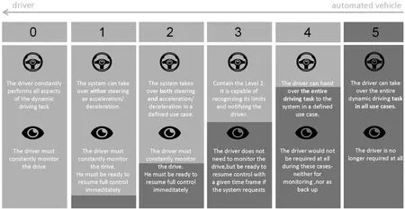
Figure1.The responsibility of driver and system in different levels[1]
Level 3 is currently more controversial topics in the field of automated driving,because automated driving primary responsibility for Level 3 is the driver rather than the system.Figure 1 shows the responsibility of driver and system in different levels,and dark blue represents the degree of automated driving system involvement.On the other hand,Level 3 are different between Level 4 and Level 5 by their fallback operation,Level 3 system needs to hold for a certain amount of time before the driver takes over,however the Level 4 and Level 5 system does not require driver any more,it can even cancel the steering wheel and brakepedal(i.e.Cruise AV from GM).
Therefore,for the OEMs,as long as the automated driving level is higher than Level 3,it is necessary to ensure the absolute safety of the vehicle's automated driving system.With the launch of automated driving technology,safety design has become the most important consideration for automated driving.NHTSA released“AUTOMATED DRIVING SYSTEMS 2.0:A Vision for Safety”in September 2017.This document highlights 12 safety elements to consider for autonomous driving[2].The goal is to ensure that automated driving technology is safe throughout the entire process.The most important factors of automated driving are human,vehicles and the environment.Level 4 and Level 5 does not have driver anymore,the human's factor is only considered in Level 3.Table 1 shows the safety aspects to be considered for the three factors.
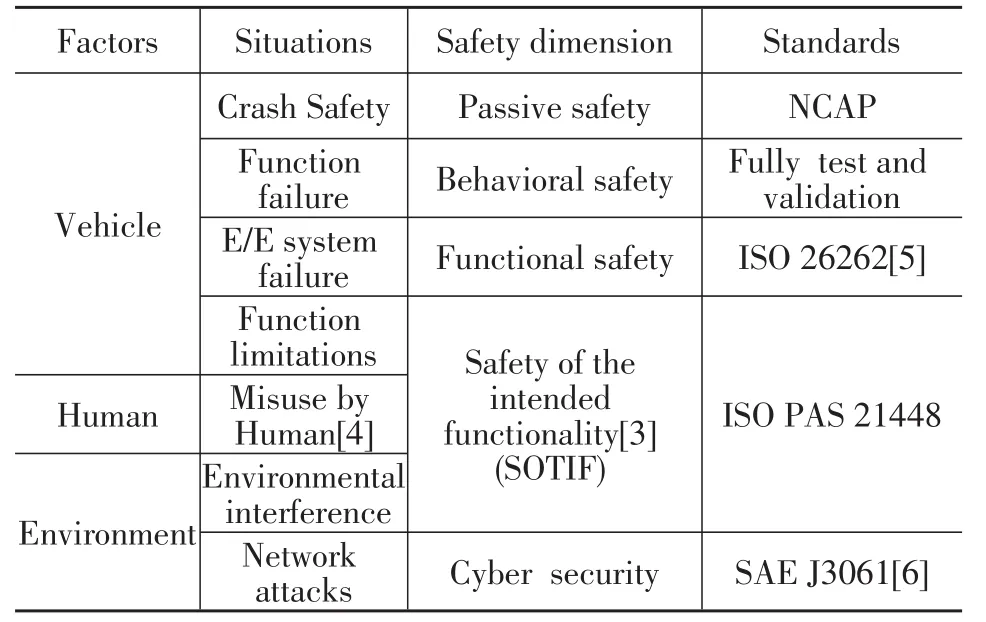
Table1.Safety aspects tobe considered for the 3 factors
In recent years,a large number of studies on the safety of automated driving are relatively broad.This study focuses on the vehicle itself,which discusses how to design a new E/E architecture to meet the safety needs of automated drivingvehicle.
Thefallback of Autopilot
Vehicles with lower levels of automation rely on a human driver to take back control if a situation on the road becomes too complex for the technology to handle,or if the technology itself fails.But the Level 3 and above automated driving vehicle must be robust enough to handle these situations on its own.If the vehicle fails,the vehicle will fall back to a safe state.This might include situations when the automated driving system experiences problems,when the vehicle is involved in a collision,or when environmental conditions change in a way that would affect safe driving beyond the operational design domain.On the other hand,the backup requirements for different levels of autonomous driving are not exactly the same.Scenario is the mainline of autonomous vehicle design.The reliability of autonomous vehicle depends on the completeness of the scenario library.If a scenario that was not taken into account during the design process actually occurred while in automated driving mode,the system will not be able to handle it,and serious accidents may even occurred.Similarly,fallback requirements are also derived from the scenario library.The fallback requirements in every scenario are must be considered
The automated driving system should be designed to meet every fallback requirement.This paper presents a methodology for deriving fallback requirement,it provides the foundation for the design and verification of automated driving system.It should be noted that because the logic algorithm of driver takeover requires complex and reasonable Human Machine Interface(HMI)design,so this paper only covers the fallback requirements when the driver did not take over(Level 3)or need not to take over(Level 4 and Level 5).
The example of fallback requirements derivation process is shown in Table 2.When dealing with the same situation,the backup requirements are different in different situations.For example,if a single point of failure of the braking system occurred during the automatic parking,because the brake system is redundant backup which can still meet the performance in low-speed conditions,due to the system can continue to complete the automatic parking.If the same fault occurs at Traffic Jam Pilot,the braking system will fail or degrade,the vehicle should stop in the current lane.If it occurs at Highway Pilot,the vehicle should stop in emergency lane to prevent affecting other driving vehicles.If it occurs at Urban Pilot,the vehicle should reduce the speed and stop in a safe place.
In order to make safe driving technology safer,It is necessary to establish a basic fallback library in the early stages of automated driving system design.With the simulation and validation of automated driving system development,it can also continue to improve the fallback library,then meet the new fallback requirements through software iteration even hardware upgrade.
The safety design of EEA
The safety of a self-driving vehicle itself consists of 3 layers.
●Layer1:Individual ECU
Hardware Security Module
Protect integrity of ECU SW&data
●Layer2:EEA in the vehicle
Separate domains by gateway
Firewalls in the vehicle
Redundant systems
●Layer3:Firewalls
Outside vehicle firewalls
Security standards for external interfaces
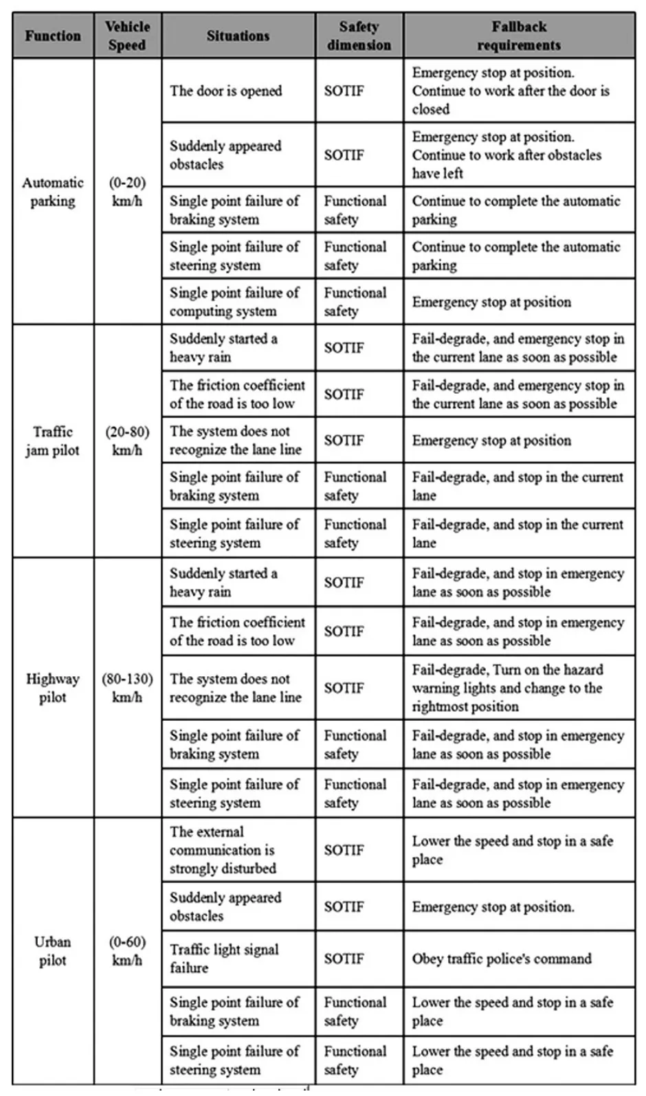
Table2.The example of fall back requirement derivation process
The E/E architecture is the top-level design of the electrical and electronic system.It is a comprehensive work that contains requirements analysis,functional definition, system configuration definition, network topology,and functional verification.Therefore,in order to ensure the security of subsystems and functions,a topdown design from the E/E safety and security architecture isrequired.
This study focuses on the Layer 2.The safety design of the E/E architecture of autonomous vehicles mainly considers the following aspects:
●Secure network topology
●The main control system redundancy
●The brake system redundancy
●The steering system redundancy
●The power supply redundancy
●The communication redundancy
●The sensor redundancy
The design of each aspect will be described in the following sections.
Secure network topology
The new EEA network topology design is shown in Figure 2.The topology consists of central security gateway and 5 domain controllers,which contain body domain,infotainment domain,powertrain domain,chassis domain and autopilot domain.The backbone of this EEA is Ethernet(Due to the fact that the TSN protocol is temporarily unavailable for mass production on vehicles,it still uses the CAN bus as a backup network for domains that requiring high real-time,like powertrain,chassis and autopilot).The central gateway plays an important role in data transmission in the vehicle.In order to control the communication between the security domain layer isolation within the vehicle architecture strictly,for example,do not allow the most vulnerable attacked infotainment domain communicate with autopilot domain directly,as well as the security risk of external requests for identity authentication,at the top of the architecture,a gateway firewall is introduced to ensure that only ECU nodes in the same domain and reliable users or services can legitimately interact with the target node.
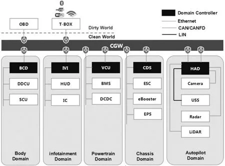
Figure2.The network topology of EEA
In this EEA,T-BOX is the only entrance to the outside of the vehicle wireless communication,and the OBD interface is the only entrance to the outside of the vehicle wired communication.The central security gateway is the firewall between in-vehicle and external-vehicle,through its powerful feature-rich firewall to achieve“clean world”and the“dirty world”outside isolation,which plays a crucial role in the vehicle's cyber security,in Figure 2,the firewall functions of the CGW include message whitelist,blacklist,Deep Packet Inspection(DPI),Message Authentication Code(MAC),Digital signature verification,etc.,the firewall also loads a dedicated hardware security module for efficient encryption and decryption operations to enhance security.In the automated driving functions,the CGWthrough physical isolation and firewall features to prevent vehicles from being remotely controlled by hackers,However,the Highly Automated Driving(HAD)system itself also needs enough security to prevent the gateway from being compromised as the last layer of protection.
The main control system redundancy
As mentioned in the previous section,Level 3 autopilot allows drivers to take over in hazardous conditions.Therefore,if the HMI for driver takes over is designed to be reasonable enough,it can reduce the complexity of the HAD system,ultimately Level 3 autopilot responsibility is the driver.Satoshi Otsuka and Kohei Sakurai had proposed a safety concept based on a“safety sustainer”for highly automated driving systems.The safety sustainer is designed for keeping a vehicle in a safe state for several seconds if a failure occurs in the system and notifying the driver that the system is in failure mode and requesting the driver to take over control of the vehicle[7].It can reduce the cost of automated driving vehicles by canceling the redundancy of system.It should be noted that the method above is only suitable for low-speed automated driving,like Traffic Jam Pilot(TJP).Due to the slow speed,even the driver does not take over the vehicle after the system reminds,the vehicle can be braked directly after HAD has failed,this operation has less impact on other vehicles on the road,so it is acceptable.If HAD fails during high-speed autopilot,like Highway Pilot(HWP),and the driver does not take over after receiving the alert for a certain period of time,the vehicles must not be allowed to brake directly in the current lane,this operation can lead to serious accidents like a rear-end collision.In the situation,the vehicle needs to continue to drive automatically to the emergency lane or to a safe state within a certain time.Therefore,HAD must be backed up to deal with high-speed automated driving and other similar conditions.
On the other hand,the HAD redundancy is required for Level 4 or Level 5 automated driving,because Level 4 or Level 5 automated driving is completely responsible for the vehicle system.In any fault situation(including the internal E/E system failure,the external environment caused the failure,such as collision and water penetration),the vehicle system needs to ensure that the vehicle can be automatically driven or automatically reach a safe state.In summary,the HAD redundancy is necessary under the following conditions:
●In condition of high speed by Level 3 automated driving
●Under all conditionsby Level 4 automated driving
●Under all conditionsby Level 5 automated driving
The redundant design of the main control system is shown in Figure 3.HAD and CDS are redundant with each other as automated driving controllers.When HAD is running normally,HAD is responsible for the perception,decision-making,path planning and vehicle dynamics control in automated driving mode.If the function of HAD completely failed,CDS will take over the control of automated driving.The CDS can store perception,decision,path planning data from the HAD for a certain time before and after HAD failure.The amount of time it can store data depends on the performance of the HAD and the data storage capabilities of the CDS.Once CDS takes over the control of automated driving,it will put the vehicle in a safe state based on stored data from HAD as well as the front camera and three radars(front radar,right side radar and left side radar).CDS only needs to receive the result data processed by radars and front camera,without having to deal with the raw data,so the hardware configuration of CDS can be much lower than HAD.Such a design can significantly reduce the cost of the automated driving computing system.In addition,CDS is also responsible for the coordinated control of the chassis domain.
It should be noted that the redundancy design of the main control system above is a way to fail-degraded,so it can not meet the Level 5 automated driving requirements,which are not allowed for fail-degraded under any condition.

Figure3.There dundant design of the main control system
The brake system redundancy
Currently,brake system of the vehicle without automated driving function of (≤Level 2)generally consists of ESC and vacuum booster system.The brake system of an automated driving vehicle must be able to respond to external braking requests,which are the basic requirements for automated driving.The traditional vacuum booster system relies entirely on the vacuum force that the driver depresses on the brake pedal,so it is impossible to respond to external braking requests.At present,most of the ESC can achieve active braking,for example,it is common to see longitudinal deceleration control with activated ACC function,HBA(Hydraulic Brake Assist)and HHC(Hill Hold Control),etc.,are achieved through the ESC active braking.However,in the Level 3 and above automated driving vehicles,once the ESC fails,the vehicle will lose the active braking capability in the automated driving mode,which is very dangerous for the users in the car.Therefore,the active braking function of the braking system must be redundant as long as the vehicle has Level 3 and above automatic driving ability,in other words,in addition to the ESC,an additional system that can responds to external braking requests is required instead of the traditional vacuum booster system.
In order to solve this problem,the new EEA selects the electrical brake booster system(called e Booster in the VDA standard)and the ESC to form a redundant braking system for each other,so as to meet the requirements of the autonomous driving system.Why choose e Booster system in the new EEA? In addition to the redundant requirements,the reareseveral reasonsbelow:
1)e Booster can improve the braking system response speed greatly,thereby shortening the braking distance,and this performance improvement can increase the scope of automatic driving ODD(Operational Design Domain).The response time of e Booster is 120 ms to 150 ms,which is 200 ms to 300 ms shorter than the response time of the ESC module,which means if the vehicles at speeds of 100 km/h,the braking distances for vehicles with e Booster can be reduced by 6 mto 9 m.
2)When working in coordination with ESC,eBooster achieves almost 100%recovery of braking energy,not only increases the cruising range of EV and PHEV,but also reduces the fuel consumption and carbon dioxide emissions of PHEV,which contributes to improving urban air quality.
3)The e Booster can apply reverse torque to the brake pedal while braking,which in turn changes the brake pedal effort,so the e Booster system can adjust the brake pedal effort to make driving more enjoyable.
The EEA of braking system is shown in Figure 4.In normal operating mode,ESC is the primary controller of the brake system,in this case,the interface between ESC and e Booster refers to the VDA standard[8].ECS and e Booster interact with each other through the CAN bus in real-time to determine if the other system has failed.The fault types include power supply failure,communication failure,system function failure and the sensor failure.If the ESC fails in any condition above,the braking request from the upper system will be executed by e Booster.Although e Booster can not control the brake pressure of each wheel cylinder,eBooster can still achieve the basic ABS and TCS functions based on the four wheel speed sensors(WSS)that are backed up to prevent the vehicle from slipping,this is a protection for the lateral stability of the vehicle.If the e Booster fails in any condition above,the braking request from the upper system will be executed by ESC,it can achieve most of the braking function,but braking performance will be reduced,the braking system will enter the fail-degraded state.Therefore,in the automated driving mode,especially in the high-speed automated driving mode,the upper system needs to actively change the vehicle track following strategy according to the reduction of the braking performance.Even if both ESC and e Booster fail,the driver can still apply mechanical braking through the mechanical structure of the braking system.
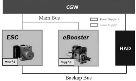
Figure4.The EEA of braking system[8]
The steering system redundancy
Similar to the braking system,the steering system also requires redundant design in Level 3 and above automated driving vehicles.The EEA of steering system is shown in Figure 5.In order to achieve Level 4 automated driving,EPS should meet this level of functional safety requirements in product design and adopt higher redundancy architecture.The hardware topology needs to meet the following requirements.
●Two separate ECUs,each with its own power supply and communication.
●Two dual-core processor MCUs,the functional safety level reached ASIL D.
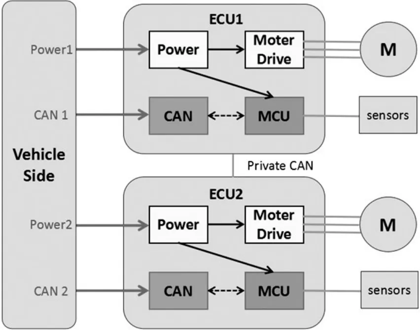
Figure5.The EEA of steering system
●Two torque sensors,the functional safety level reached ASIL D.
●Two angle sensors,the functional safety level reached ASIL D.
●Two current sensors.
●Two motor position sensors.
●Two independent power management chips for MCU power supply,the functional safety level reached ASIL D.
●Two motor drive chips,the functional safety level reached ASIL D.
●The motor uses 6-phase windings,each 3-phase windings driven by a separate driver chip.
Under normal conditions,the two ECUs verify each other through private CAN.Once any of the ECUs fails,another ECU takes over steering assist to achieve faildegrade.If any sensor has a single point of failure,one of the ECUs will send backup sensor signal to another ECU via private CAN,which guarantee the function and performance of the steering system will not be affected.If one group of the motor windings fails,the steering system will be enter the fail-degrade status,another group of motor windings will achieve 50%assist.In addition to the basic functions of the EPS,the steering systems for vehicles with automated driving should have the following features.
●External steering angle response function:Responding to the control activation signal and angle control signal issued by the upper system;
●In order to ensure the safety of the system,EPS needs to monitor its own status and the signal reliability of the upper system in real time.If a fault is detected,the EPS system performs redundancy and notifies the upper system.
●Determine whether the driver is operating the steering wheel,if the steering wheel torque exceeds the threshold of takeover by driver,EPS will cancel the angle response function.
The power supply redundancy
The above sections have mentioned that several important systems of automated driving vehicles require power redundancy.Similar to the design concept of system redundancy,the power supply redundancy requires that the power supply system of the vehicle can keep available after a single point of failure.It will puts forward new requirements for power distribution scheme of the vehicle.In this new EEA,a low-cost solution to the redundancy of the power supply system is proposed.By optimizing the power distribution design,redundancy is realized without increasing the power supply components(such as extra battery or DCDC).
The vehicle's power supply system consists of a number of components:power modules,fuses,fuse boxes,wiring harness and ground point.Failure of any one of the components will result in the failure of the corresponding power supply circuit,which leads to the function failure.The redundant power distribution scheme for automated driving vehicle is shown in Figure 6.Each component is labeled in the figure,and the single point failure analysis of power supply system is shown in Table 3,it can be seen that any single point of failure will not lead to functional failure.
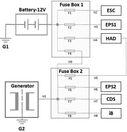
Figure6.The redundant power distribution scheme
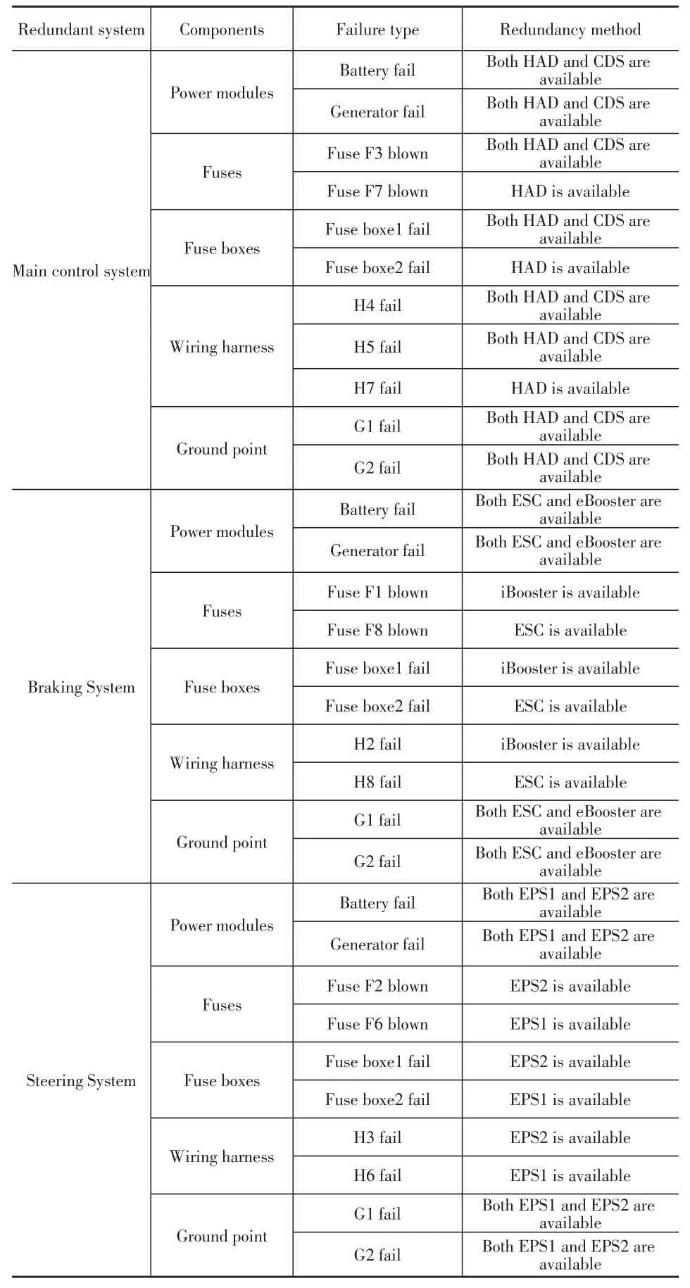
Table3.Single point failure analysis of power supply system
It should be noted that,in the case of power module redundancy,all low-voltage power supply of the vehicle is provided by the 12 V battery,once the generator(it should be DCDC on the EV)fails,and the 12 V battery can only be maintained for a certain period of time,that depending on the capacity of 12 V battery,the State Of Charge(SOC)of battery,and the vehicle's low-voltage power load.It requires the time that battery can be sustained power supply should be longer than the time it takes for the vehicle to reach a safe state in automated driving mode.In order to ensure that the vehicle can maintain enough time in automated driving mode,it requires special design of energy management strategy that turn off unnecessary load immediately(such as infotainment system,body comfort system).The energy management strategy should ensure that the necessary systems for automated driving can work properly(such as the drive system,brake system,steering system,main controller,and related sensors).On the other hand,due to different failure modes lead to different levels of risk,all the failure modes should correspond to different fall back strategies,which are parts of the fall back design methodology.
The communication redundancy
Currently,in some industry field with high reliability requirements(such as aerospace,marine,railways,etc.),redundant communications are usually used,which fault detection and switching strategies with high real-time performance ensure that after a network failure,another network communication is still valid.However,the traditional vehicle without automated driving function only performs redundancy verification on the CAN bus signal in the software layer.Vehicles with Level 2 and below features are fully controllable by the driver,so that even if a bus communication fails,the vehicle remains under control.However for Level 3 and above autonomous vehicles,the important system must have communication redundancy,the systems that require communication redundancy include:Main control system,Braking system,Steering system.There are two kinds of CAN hardware redundancy scheme,the Type 1 is CAN controller level redundancy,and the Type 2 is MCU-level redundancy.In order to ensure the safety of communication,all the redundancy systems need Type 2 as shown in Figure 7.

Figure7.The communication redundancy scheme
In normal working conditions,both the master CAN and the backup CAN can transmit message,so that after the fault is recognized,the switching information can be transmitted through the backup bus.The transmission of the switching information can not be affected even if the working bus was interfered.Whatever fault occurs,once a node identifies a fault and confirms that a fault has occurred,the master MCU can inform the backup MCU through internal communications and send a takeover message to the backup CAN.The time required to complete the switch depends on the fault identification time required by the first node that identified the fault.
There are self-recovery fault and not self-recovery fault about CAN bus failure.Depending on the severity,failure of the CAN bus can generally result in 3 failure consequences below,but not every failure requires a switch to backup CAN.
1)One node failure:the node can not send and receive message.
2)CAN bus failure:most of the nodes can not send and receive message.
3)Error frame:the reareerror frames on the CANbus.
This document specifies the types of faults that require redundant switching,as shown in Table 4.
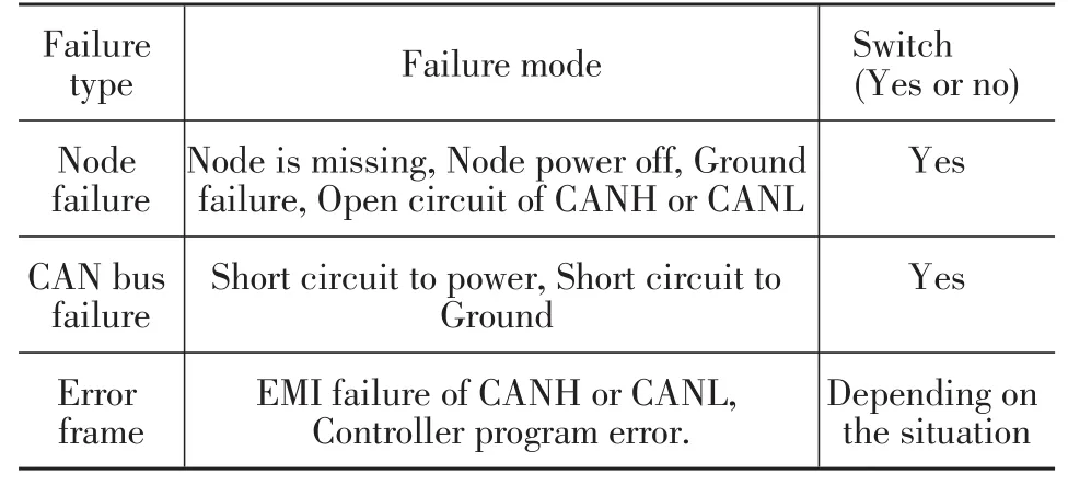
Table4.The requirements of redundant switching
The sensor redundancy
Sensor selection should consider the vehicle positioning and the cost target of the ADAS.Once the sensor selection is determined,the transmission bandwidth and process speed of the ADAScan be calculated,so this is the basis of the hardware design and algorithm design.Lidar can get a better performance,but its price is a major crisis in practical applications.Meanwhile,radar is a more affordable option which can also provide satisfying performance.It is more compact design and robust to various weather conditions.Some 77 GHz radars can measure up to 200 m,which is important in driver modelling,especially in highway scenarios.Meanwhile,radar has been widely adopted in the automobile industry,mainly for adaptive cruise control and collision avoidance.Binocular cameras are more commonly used as range finder,some studies indicate that monocular cameras can also measure distance under some assumptions.
Different sensors have different performance and advantages,as shown in Table 5
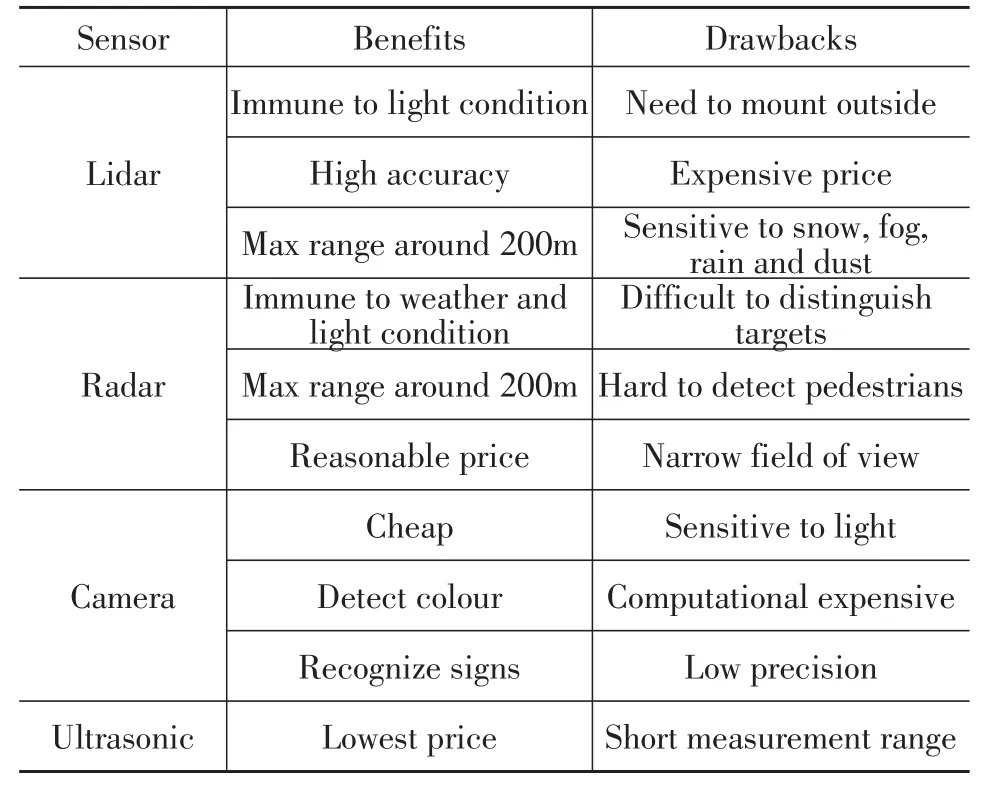
Table5.Comparison between different sensors
As the scenario of ADS is complex,we can’t use single sensor in ADS design,multiple sensor fusion is an inevitable trend.For different OEDR requirements,there are different sensor could be chosen.
Table 6 shows an example of sensors could be selected according to different OEDR requirement.
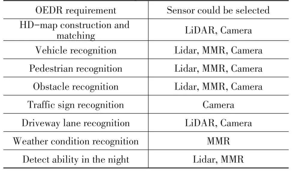
Table6.Example of sensor selection
Discussion
The safety redundancy design is endless,In theory,the more redundant means the more safe of automated driving system,but this also means that the cost of the vehicle increases.For the OEMs,the purpose of developing a car is for mass production and profitability,therefore,it must take into account cost factors in the redundant design.For this reason,the safety design of EEA mentioned in this paper considers the use of low-cost solutions in many ways,such as the power supply redundancy and the main control system redundancy.This EEA supports up to Level 4 automated driving in some scenarios,the specific scenarios that can be supported are determined by the performance of each system and the algorithms of automated driving.
If people want to cover the scene library for automatic driving more completely,considering only the redundancy of the vehicle EEA can not meet all the safety requirements,The high-precision maps and V2X must be introduced as a complementary to the perception,and need to enhance the performance of the actuator,for example,the introduction of chassis domain coordination control to improve vehicle stability in automated driving mode.In fact,these similar needs are based on Level 4 autopilot scenario library and fall back library design.It needs to be considered that how to ensure the scenario library and the fall back library completely and reasonable.
Summary/Conclusions
Based on SAE's classification of automated driving,this paper summarizes the safety factors of automated driving system from the aspect of human,vehicle and environment,this paper also illustrates the derivation methods and idea of fall back requirements.Finally,from the perspective of the seven safety dimensions,the methodologies to design a new EEA that meets the requirements of automated driving safety are introduced,and a detailed introduction to the design of each safety dimension was presented here in the paper.
猜你喜欢
工业经济论坛(2020年6期)2020-04-13 00:38:20
汽车零部件(2019年10期)2019-11-13 06:55:26
汽车观察(2018年12期)2018-12-26 01:05:26
汽车观察(2018年10期)2018-11-06 07:05:20
现代制造技术与装备(2015年4期)2015-12-23 10:20:22
汽车纵横(2015年6期)2015-04-29 00:44:03
西北工业大学学报(2015年1期)2015-02-22 00:29:19
西北工业大学学报(2015年1期)2015-02-22 00:29:19
沈阳医学院学报(2014年4期)2014-12-27 13:44:34
汽车零部件(2014年4期)2014-06-23 13:53:47
