Horizontal-Based Orchestration for Multi-Domain SFC in SDN/NFV-Enabled Satellite/Terrestrial Networks
Guanglei Li, Huachun Zhou*, Bohao Feng, Guanwen Li, Qi Xu
School of Electronic and Information Engineering, Beijing Jiaotong University, Beijing 100044, China
I. INTRODUCTION
With the development of satellite communications and network technologies, the integration of satellite network and terrestrial network has gotten much attention. Satellite communications can play an important role in future communication networks [1]. An integrated satellite and ground communication network brings many benefits, such as improved service coverage and footprint expansion, rapid dynamic and/or infrastructure-independent service deployment, increased network resilience, broader range of service provisioning with lower costs and improved Quality of Service/Experience (QoS/QoE). Software-De fined Networking (SDN) and Network Functions Virtualization (NFV) technologies have many advantages for future network. It’s promising to use SDN and NFV to integrate satellite and terrestrial networks[2][3].
Satellite network consists of access subsystem, core subsystem and control & management subsystem [1]. Figure 1 shows their components. The access subsystem consists of satellite terminals (STs), satellite gateways(GWs) and communication satellites. The core subsystem consists of backbone network with IP/Multi-Protocol Label Switching (MPLS)and/or Carrier Grade Ethernet technologies and Point of Reference (PoPs). Satellite GWs and PoPs are connected by the backbone network. The control and management subsystem consists of Network Control Centre (NCC)and Network Management Centre (NMC),which control connection and manage the system elements in satellite network respectively.GWs are co-located with their NCC and NMC and they are referenced as satellite hub. The backbone network, satellite hub and Customer Premise Equipment (CPE) are the places to implement network functions such as Performance Enhancing Proxy (PEP), HTTP content caching, switch and routers.
In this paper, we propose a horizontal-based multi-domain orchestration framework for Md-SFC in SDN/NFV-enabled satellite and terrestrial networks.
Figure 2 shows a hybrid access scenario,where satellite network and terrestrial network both provide network access for customers.The hybrid access has benefits such as high network availability and seamless alternative/optimal access choice [1]. The SDN-enabled hybrid CPE makes it easy to steer traf fic and switch between satellite access and terrestrial access. The SDN-enabled satellite hub and backbone network make it possible to handover in time for STs, if the hub it connects suffers signal degradation due to meteorological events such as clouds or rain [3]. In the NFV-enabled satellite network, network functions such as PEP, NAT and firewall can also be virtualized and instantiated as required,which improves flexibility and reduces costs.Depending on SDN and NFV, it’s feasible to construct SFC flexibly and dynamically in an integrated satellite and terrestrial network.

Fig. 1. Satellite networks.
Reference [2] uses a federated network resources manager to manage and control terrestrial and satellite communication segments.A unified control plane is proposed to integrate and optimize the operation of the hybrid network. However, it only focus on the edge network. End-to-end multi-domain SFC orchestration is not taken into consideration, either. In this paper, we consider a multi-domain situation, where user traf fic may pass through different operators’ domain and visit a remote datacenter, we propose to use a Multi-domain Orchestrator (MdO) to integrate and orchestrate the hybrid network. Furthermore,we design a horizontal-based multi-domain orchestration framework to realize end-to-end orchestration and cooperation between operators.
We organize this paper as follows. Sec. II gives related work about SDN, NFV and SFC.In Sec. III, we propose a horizontal-based Md-SFC orchestration framework. Sec. IV presents an Md-SFC mapping algorithm including intra-domain mapping and inter-domain mapping. Sec. V gives evaluation of the framework and algorithm. Sec. VI concludes this paper.
II. RELATED WORK
SDN decouples network control from forwarding with programmable ability. With the decoupling and programmability, SDN brings many benefits such as efficient configuration,improved performance, higher flexibility and encouraged innovation [4]. European Telecommunications Standards Institute (ETSI)NFV [5] architecture virtualizes network functions and enables dynamic and flexible selection of service functions. In ETSI NFV architecture, Network Function Forwarding Graph (VNF-FG), which consists of multiple network functions, is defined to describe Network Service (NS). IETF Service Function Chaining (SFC) working group also proposes the SFC architecture in RFC 7665 [6]. A service function chain defines an ordered set of network Service Functions (SFs) for delivery of end-to-end services. RFC 7498 [7]describes problems the group aims to address,including topological dependencies, configuration complexity, application of service policy,limited end-to-end service visibility and etc.Reference [8] designs a protocol named Network Service Header (NSH) to decouple the service from topology. An intelligent control plane is proposed to construct service function chains but does not consider the multi-domain situation [9].
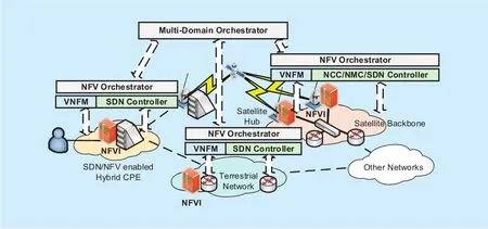
Fig. 2. A hybrid access scenario.
As orchestration technology matures and brings benefits in cloud environment, orchestration in communication networks has been a hotpot of SDN and NFV research. Moreover, orchestration for end-to-end service in multi-domain environment has got much attention recently. ETSI NFV designs a basic frame for NFV Management and Orchestration(MANO). It defines Virtualized infrastructure manager (VIM), VNF Manager (VNFM) and NFV Orchestrator (NFVO) for management and orchestration of Network Functions Virtualization Infrastructure (NFVI), Virtualized Network Functions (VNF) and Network Services [10]. Multi-domain NFV and orchestration is a hot research topic. Reference [11]gives many motivating use cases of distributed multi-domain NFV and potential benefits such as bandwidth negotiation across different domains. It indicates that connected-centered NFV-MANO, placement of control plane,business model and etc. are challenges and research directions. The Unify [12] architecture proposes a recursive orchestration method for multi-domain NFV. Focusing on endto-end connectivity in cloud computing, the authors in [13] compare two different SDN orchestration architecture. The authors in [14]summary SDN Orchestration approaches for Data Center Multi-Domain Optical Networks,including single controller model, multiple SDN controllers in mesh and in a hierarchical setting. NFV research group of IRTF also pays attention to multi-domain situation. Draft [15]discusses “Hierarchical” and “Cascading” architectural approaches and relies on a trading agent such as Entry-Point Provider. Focusing on data plane, draft [16] in SFC working group designs a hierarchical architecture for multi-domain SFC controlled by the same organization. We focus on control plane and submit a draft [17]. We consider inter-domain negotiation between different organizations and propose to use horizontal interfaces.
Building on the basic frame of NFV, we design a distributed orchestration framework for multi-domain (multi-operator, multi-administer and multi-technology) SFC in SDN/NFV-enabled satellite and terrestrial networks.Horizontal interfaces are used for inter-domain cooperation. A heuristic SFC mapping algorithm and a cooperative inter-domain path cal-culation method are furtherly proposed to map service function chains to infrastructures. In this method, operators do not need to provide topology information to others. The master multi-domain orchestrator and intra-domain orchestrators coordinate to select proper inter-domain links.
In this paper we do not give implementation of the MdO and intra-domain NFV orchestrator. Orchestrators designed in the literatures usually takes advantages of the network abstractions, programmability and resources allocations ability provided by SDN,NFV or cloud control and management components, although they have different points of focus. Focusing on traf fic steering in SFC,the authors in [18] conclude works of academic researchers, industry, standards and open source communities and propose a L2-based Openflow-OpenDaylight chaining solution in the NFV scenario. Related works in data plane are orthogonal with our works and can be used for future implementation. In our framework,SDN controllers should expose its northbound interface to the intra-domain NFV orchestrator and intra-domain NFV orchestrator should expose its north-bound interface to the MdO. SDN is utilized to connect intra-domain service functions but also construct inter-domain chains.
III. HORIZONTAL-BASED MULTIDOMAIN SFC ORCHESTRATION
In this section, we describe the proposed orchestration framework. Firstly, we give an overview of the framework. Then, we give an Md-SFC example with the hybrid access scenario.
3.1 Overview
As network service functions span different administrative domains, multi-domain orchestration is needed to make better utilization of resources. And we believe end-toend inter-domain service performance can be guaranteed by cooperation. By flow steering,the MdO in the hybrid access scenario can integrate and share terrestrial network resources and satellite network for access service. And when the flow passes through other operators’domains, inter-domain cooperation is needed to ensure good end-to-end performance.Figure 3 presents a scenario where user traf fic pass-es multi-operators’ domains to visit a cloud datacenter (DC). The operator 1 owns the hybrid satellite and terrestrial network. The SDN transport network is managed by operator 2 and connects the access network and DC(owned by operator 3). To make it possible to orchestrate multi-operator domains, a horizontal-based orchestration framework is designed.Comparing with vertical control, we believe that horizontal interfaces make operators more willing to cooperate with each other. In this framework, MdOs communicate with each other by message exchange and no one is on top of everything. That can avoid vendor lockin even though a certain super orchestrator is able to coordinate many domains.
In figure 3, we assume all operators have their own MdOs. In each network, a Domain NFV Orchestrator (DoNFVO) presents the domain in a centralized way, with knowledge of resources and topology information in the domain. MdOs coordinate DoNFVOs by vertical interfaces. To orchestrate the multi-domain network in a global view, a master orchestrator should be selected from MdOs to coordinate other MdOs by horizontal interfaces. As users access to operator 1’s domain in our use case,the MdO of operator 1 is the best choice for the master orchestrator. MdO 1 forwards the Md-SFC request to other MdOs by signal messages and informs DoNFVOs it controlled by vertical interfaces. Other MdOs become slave orchestrators and also inform DoNFVOs by vertical interfaces. DoNFVOs are responsible for intra-domain orchestration computation.The master MdO collects orchestration results from slave orchestrators and DoNFVOs it controlled. Then, the master MdO makes a Md-SFC installation decision. In this way, a service function chain spanning multi-domain can be mapped to infrastructures.
3.2 Md-SFC example
In figure 3, we assume a user requests a service chain for video stream with bandwidth demand and hope the end-to-end delay is as less as possible. The video server is located in the cloud data center and the flow has to pass through 4 domains (CPE domain, satellite or terrestrial network, a transport domain and the cloud domain).
In general, a service function chain has typical SF combination. We presume a service layer translates users’ demand into specific function combination. As figure 4 (a) shows,according to the domains’ attribute, location and role it plays in the Md-SFC provisioning,the service layer of operator 1 divides the request into five specific Sub-SFCs for each domain and one of them is an generalized transport function (Sub-SFC3). Each domain receives a request with performance demand and orchestrates for this Sub-SFC including selecting proper psychical nodes for SFs and psychical paths for virtual links between SFs.After intra-domain orchestration computation, each domain replies results to the master MdO. If all domains’ mapping succeed, the master MdO will hold a global view like figure 4 (b) shows. It contains the alternative Sub-SFC2-1 and Sub-SFC2-2, and if there are more interconnected domains or administrative networks, there will be more candidate Sub-SFCs.
IV. MD-SFC MAPPING ALGORITHM

Fig. 4. Md-SFC example.
In this section, we describe a Md-SFC map-ping algorithm based on the proposed orchestration framework. The SFC mapping problem is similar to Virtual Network Embedding(VNE) problem, which is NP-hard. Approaches used in VNE can be utilized in SFC mapping, but we do not discuss requests online process and scheduling in this paper. Differing from a virtual network, a flow usually passes through all SFs and virtual links in a service function chain. Bandwidth performance of a chain is decided by the bottleneck virtual link and end-to-end delay of a Md-SFC is decided by chosen Sub-SFCs and inter-domain paths.Our algorithm is modified from a VNE approach. We use greedy algorithm for SF mapping and K-Shortest Paths (KSP) algorithm for virtual link mapping [19].
4.1 Problem formulatio n
To formulate SFC mapping problem, firstly we discuss it in a single domain. Figure 5 depicts two SFC requests mapped onto the same infrastructures. That a SF sfiis mapped onto a physical node nscan be denoted as (1). That a virtual link l (sfi, sfj) between sfiand sfjis mapped onto a physical path Wlis denoted as (2).

Fig. 5. SFCs mapped onto infrastructures.

Fig. 6. A Md-SFC mapped onto inter-connected domains.

To instantiate a chain, computation resources and bandwidth resources of infrastructures should be allocated to SFs and virtual links.Resources constraint can be denoted by (3),(4) and (5), where CPU(sfi) and Mem(sfi) present CPU and memory resource needed by sfiand B(l(sfi,sfj)) presents bandwidth demand of virtual link l(sfi,sfj). Similarly, CPU(ns) and Mem(ns) present remaining CPU and memory resources of node ns, B(l(ns, nt)) presents remaining bandwidth resources of physical link l(ns, nt) between node nsand nt.

We use a directed graph S = (SF, CSF, LS,CL) to denote a SFC. SF presents the set of service functions and LSpresents virtual links between them. CSFpresents the set of constrains to SFs, including functional constrains such as service function type and variable parameters such as CPU and memory. CLpresents the set of constrains to links such as bandwidth and delay. An undirected graph I = (N, PN, LN, PL)is used to present the infrastructure network.N presents the set of physical nodes and LNpresents the set of physical links. Similarly, PNand PLpresent the parameters of substructure nodes (SF instance types, CPU and memory)and links (bandwidth and delay).
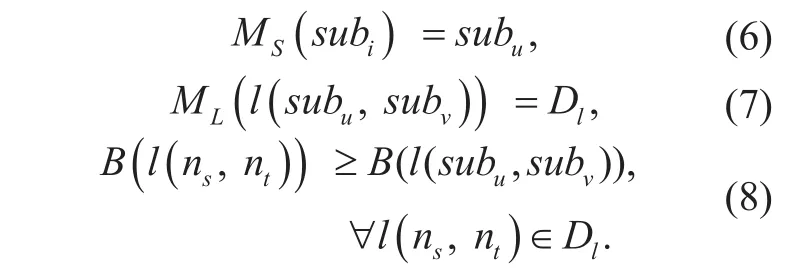
In our multi-domain situation, an Md-SFC consists of several Sub-SFCs. After all domains’ intra-domain mapping finished,inter-domain mapping chooses candidates according to intra-domain mapping results. Selecting candidate Sub-SFCs and inter-domain paths is also regarded as a mapping process.Figure 6 depicts a Md-SFC mapped onto four inter-connected domains, where domain 2 and 3 are candidates for Sub-SFC 2 and domain 2 is selected. That a candidate Sub-SFC subuin domain u is selected to construct the Md-SFC can be denoted as (6). That a virtual link l(subu, subv) between subuand subvis mapped onto an inter-domain path Dlis denoted as (7).Similarly, remaining bandwidth of any physical link in inter-domain path Dlmust be larger than bandwidth demand, that is denoted as (8).
Delay of a Sub-SFC is the sum of its virtual links’ delay a flow will pass through and delay of a virtual link is the sum of physical links’delay it’s mapped onto. In the multi-domain situation, we aim to select proper domains and inter-domain paths from candidates to minimize end-to-end delay. The object is presented by (9), where delay(subu) presents delay of selected Sub-SFC subuand delay(Dl) presents delay of inter-domain path between selected Sub-SFCs.

DoNFVOs in each domain are responsible for Sub-SFC mapping. The master MdO is responsible for candidate Sub-SFCs and inter-domain paths selection. In section 4.2, we describe the intro-domain Sub-SFC mapping algorithm. In section 4.3 and 4.4 we further give a cooperative inter-domain mapping method and algorithm.
4.2 Intra-Domain Sub-SFC mapping
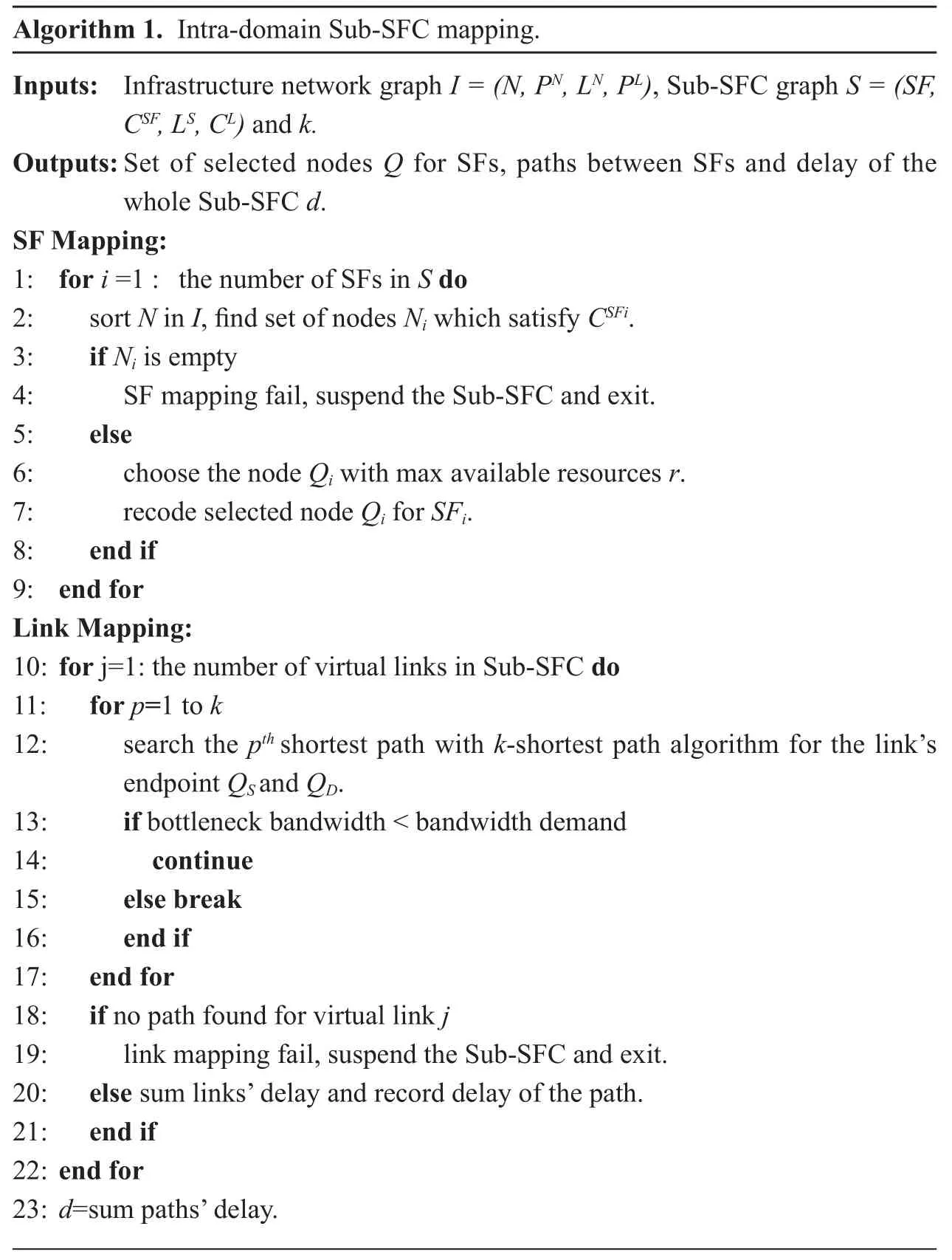
Like the decomposition of VNE problem into virtual node mapping and virtual link mapping, SFC mapping problem can be decomposed into SF mapping and virtual link mapping. We use a greedy algorithm for intra-domain SF mapping. The physical node with max available resources will be selected from all candidate nodes which have required SF type. Available resources of node n is defined as (10), where CPU(n) presents available CPU, Mem(n) presents memory capacity and L(n) presents the set of all links that the node n is adjacent to. Besides CPU and memory capacity, bandwidth is also considered for the following virtual link mapping stage. Equation (10) reflects available resources of a node comprehensively and it has low complexity when calculating node ranks. We use KSP algorithm for link mapping. Link mapping calculates physical paths for virtual links and any physical link in a physical path should have greater bandwidth than required bandwidth. At the same time, we hope delay of the path is as less as possible. The KSP algorithm finds the path satisfies bandwidth from the first k shortest paths. In a transport domain, no service function is provided but edge routers/switches selection can be regarded as SF mapping and the KSP algorithm also can be used for intra-domain path calculation. The intra-domain Sub-SFC mapping is as follows: the first phase is SF mapping which selects physical nodes for each SF using greedy algorithm; The second phase is link mapping which searches shortest paths between physical nodes until bandwidth demand is satisfied or k paths have been searched.
?

4.3 Cooperative Md-SFC mapping method
Differing from a undirected cycling virtual network, a network function chain is usually directed and acyclic. Traffic flows pass through the whole chain, thus, the performance of any sub-chain affects the end-to-end performance, and the performance of inter-domain path should also be good. Based on these factors, we propose a cooperative inter-domain mapping method and compare it with a naive uncooperative method in section V.

Fig. 7. Candidate Sub-SFC selection based-on multistage graph.

Fig. 8. Inter-domain path selection.
If the traf fic must pass through several domains in order (e.g. four cascaded domains:CPE, Satellite/Terrestrail access, Transport and DC) and each domain provides multiple candidates, the number of inter-domain path increases obviously compared with figure 4.Figure 7 presents a multistage inter-domain graph, except for the first domain, other domains provide multiple options. If there are more candidate Sub-SFCs and a upstream Sub-SFC has inter-domain paths with all downstream Sub-SFC, the number of inter-domain paths will be greater.
In an uncooperative inter-domain path mapping method, the master MdO can calculate inter-domain paths for Sub-SFCs directly using KSP algorithm, under the premise that the master MdO has enough computation ability and operators are willing to provide topology information. Besides the load of master orchestrator grows with the number of inter-domain path, that some operators may be unwilling to provide topology information is the other reason why we need a cooperative way.We hope DoNFVOs calculate inter-domain paths. However, we still hope the best edge nodes and inter-domain link can be selected from a global standpoint.
In this cooperative way, DoNFVOs calculate paths between domain’s all edge nodes and end SFs of the Sub-SFC. DoNFVOs report mapping results which contain the performance of the Sub-SFC and all candidate paths to edge nodes. The master orchestrator selects the best edge nodes for each domain according to the performance of the whole inter-domain path between Sub-SFCs. Figure 8 presents the inter-domain path selection when there are two edge nodes for each Sub-SFC. In this way, domain’s DoNFVO calculates paths to candidate edge nodes and does not need to provide topology information to the master orchestrator. The master orchestrator only compares performance and chooses the best inter-domain path. As all path search missions are finished by DoNFVOs, the computing load of the master orchestrator is light.
After inter-domain path selection between Sub-SFCs, a shortest end-to-end inter-domain path can be calculated based on delay of Sub-SFCs and their inter-domain paths. If there are many candidate Sub-SFCs, comparing every feasible end-to-end inter-domain path is not necessary. Whether or not the topology of multi-domains is a multi-stage graph, the master of orchestrator can build a general weighted multi-domain directed graph. The candidate Sub-SFC selection problem can be equivalent to single-source shortest path problem. Single-source shortest path algorithms, such as multistage graph algorithm and Dijkstra algorithm, can be used depending on different situations.

Figure 9 and (11) present how to build a weighted multi-domain directed graph. A candidate Sub-SFC and its inter-domain path with its downstream Sub-SFC can be transformed into a weighted directed edge and a vertex. In(11), dp(ij-1)presents the delay of inter-domain path between Sub-SFCs, dsub-sfc(i)presents the whole delay of Sub-SFC(i).
4.4 Inter-domain Md-SFC mapping
In the cooperative method, after intra-domain Sub-SFC mapping, the path between end SFs of a Sub-SFC and edge nodes should also be searched by DoNFVOs using KSP algorithm.DoNFVOs report not only the delay of the whole Sub-SFC but also delay of all candidate paths to edge nodes and inter-domain links.
Following is the process of cooperative inter-domain Md-SFC mapping algorithm. Firstly, the master orchestrator compares candidate inter-domain paths and chooses better ones for Sub-SFCs to build a weighted multi-domain directed graph based on domains’ mapping results. Then, based on this weighted graph, the end-to-end inter-domain path with minimum delay is selected by Dijkstra algorithm.
V. EVALUATIONS
Firstly, to verify our framework and method,we compare performance between the uncooperative and cooperative method with inter-connected satellite and terrestrial multi-domain networks. Then we compare the cooperative method with random inter-domain link selection. Our simulation is based on MATLAB.
5.1 Simulation parameters
To produce optional Sub-SFCs, we use the multi-domain topology in figure 10. Each domain is managed by different operators. Four different network topologies are used as figure 11 shows. The CERNET topology ( figure 11(a)) is used in domain 1. The USNET topology ( figure 11 (b)) is used in domain 2 and 3.The NSFNET topology ( figure 11 (c)) is used in domain 4, 5 and 6. A tree topology ( figure 11 (d)) is used in domain 7. In each topology,edge nodes are depicted in black. If not all edge nodes are connected with other domains(in domain 4 and domain 6), the upper one in the topology is used. Domain 2 is the satellite domain and four nodes depicted in gray in the USNET topology are set as (Geosynchronous Earth Orbit) GEO satellite. Domain 1 is the source of traffic and we assume domain 1’s MdO is the master MdO. It executes inter-domain mapping algorithm after intra-domain mapping stage.

Fig. 9. Weighted multi-domain directed graph.

Algorithm 2. Inter-Domain Md-SFC mapping.Inputs: Each Sub-SFC mapping result including delay of the whole Sub-SFC and delay of all paths to edge nodes, delay of all inter-domain links between edge nodes.Outputs: Selected Sub-SFC, inter-domain links and end-to-end delay.1: for i=1 : the number of domains do 2: if i is not the last domain 3: compare delay of all candidate inter-domain paths between domain i and its downstream domain. Select the one with minimum delay.4: add up the delay of Sub-SFC to the delay of its inter-domain path with downstream domain,5: add the domain i into the multi-domain graph, the sum of delay in step 4 is the weight of the edge.6: else add the last domain as the last vertex into the graph.7: end if 8: end for 9: calculate the shortest end-to-end inter-domain path based on the weighted directed graph, using single-source shortest path algorithm such as Dijkstra algorithm.10: add the delay of last domain’s Sub-SFC to the delay of the shortest interdomain path as the end-to-end delay.
We assume that each domain provides two SFs for a Md-SFC. The CPU demand of each SF is 20-25 units and memory is 10-15 units.The bandwidth demand between SFs is 20 units. 14 different Md-SFC requests are generated with random SFs.

Fig. 10. Inter-connected multiple domains.

Fig. 11. Different network topologies.
In each domain, except edge nodes which are not allowed to install SF, the probability that every network node has the required SF type is set to 0.5. CPU of nodes is 200-250 units and memory is 100-150 units. Besides domain 2 and domain 3, remaining bandwidth of links in domain 4, domain 5 and domain 6 is also set to 100-150 units (including all inter-domain links). In other domains, bandwidth is 200-300 units. Two adjacent SFs are likely to be mapped to the same node, then there is no need to calculate paths for this two SFs and delay between them can be ignored.However, in our simulation, adjacent SFs are not allowed to be installed in the same node to avoid interfering performance comparison.
Domain2 consists of space segment and two ground segments. Delay of satellite-ground links is set 120-130 ms as the altitude of GEO is about 36,000km above the equator and ground terminals or GWs could locate near or far from the equator. Two SFs must be mapped to left and right side of satellites respectively.Delay of other links is 1-2 ms. The value of k is set to 4.
5.2 Performance comparison between two methods
To verify the framework and cooperative way,we compare it with the method that master orchestrator calculates inter-domain path for Sub-SFCs directly based on global topology.Figure 12 shows end-to-end delay of 14 different Md-SFCs. Figure 13 shows the sum of bandwidth cost of physical links for each Md-SFC request, and it reflects hop counts of the end-to-end path. The larger the cost is the more hops the end-to-end path has to traverse.This two kinds of method get the same result.The 1st, 7th, 9th and 13th Md-SFC requests are mapped onto domain 1, 3, 6 and 7. The 2-6th and 8th Md-SFC requests are mapped onto domain 1, 3, 5 and 7. The 10-12th and 14th Md-SFC requests are mapped onto domain 1, 2, 4 and 7 and get larger end-toend delay. In domain 3, four paths (k=4) are searched for their virtual links between SFs or SFs to edge nodes but bandwidth demand is not satisfied. If the virtual link between two SFs fails or all virtual links from any SF to edge nodes fail, the Sub-SFC will report failure, so this four Md-SFC requests use the satellite domain. It turns out that the integrated satellite and terrestrial network brings benefits and the framework construct bandwidth guaranteed Md-SFC by horizontal-based cooperation. At the same time, domains with less delay can be selected from candidates.
Because this two methods use the same intra-domain mapping algorithm and can both find the shortest available inter-domain path for Sub-SFCs, all Md-SFC requests get the same mapping result and resource consumption is also the same since from the first Md-SFC request. It proves that the master orchestrator does not need to know each domain’s topology information and proper edge nodes can be selected by a cooperative way.
In addition, we compare this two methods’mapping delay. The mapping process consists of two stages: intra-domain mapping and inter-domain mapping. As we ignore message exchange and assume each domain’s DoNFVO starts its intra-domain mapping at the same time, the maximum intra-domain mapping delay of domains can be regarded as delay of intra-domain mapping stage. Hence, the total mapping delay is the sum of maximum intra-domain mapping delay and inter-domain mapping delay.
As figure 14 shows, in a cooperative way,DoNFVOs have to calculate paths to all edge nodes and that makes intra-domain mapping delay larger than the uncooperative way. With the growth of bandwidth resources consumption, additional paths have to be searched by DoNFVOs. For example, in the 12th Md-SFC request, it fails to find available paths between two SFs and paths between SFs and all edge nodes for the Sub-SFC in domain 3, so the mapping delay is great.

Fig. 12. End-to-end delay comparison.
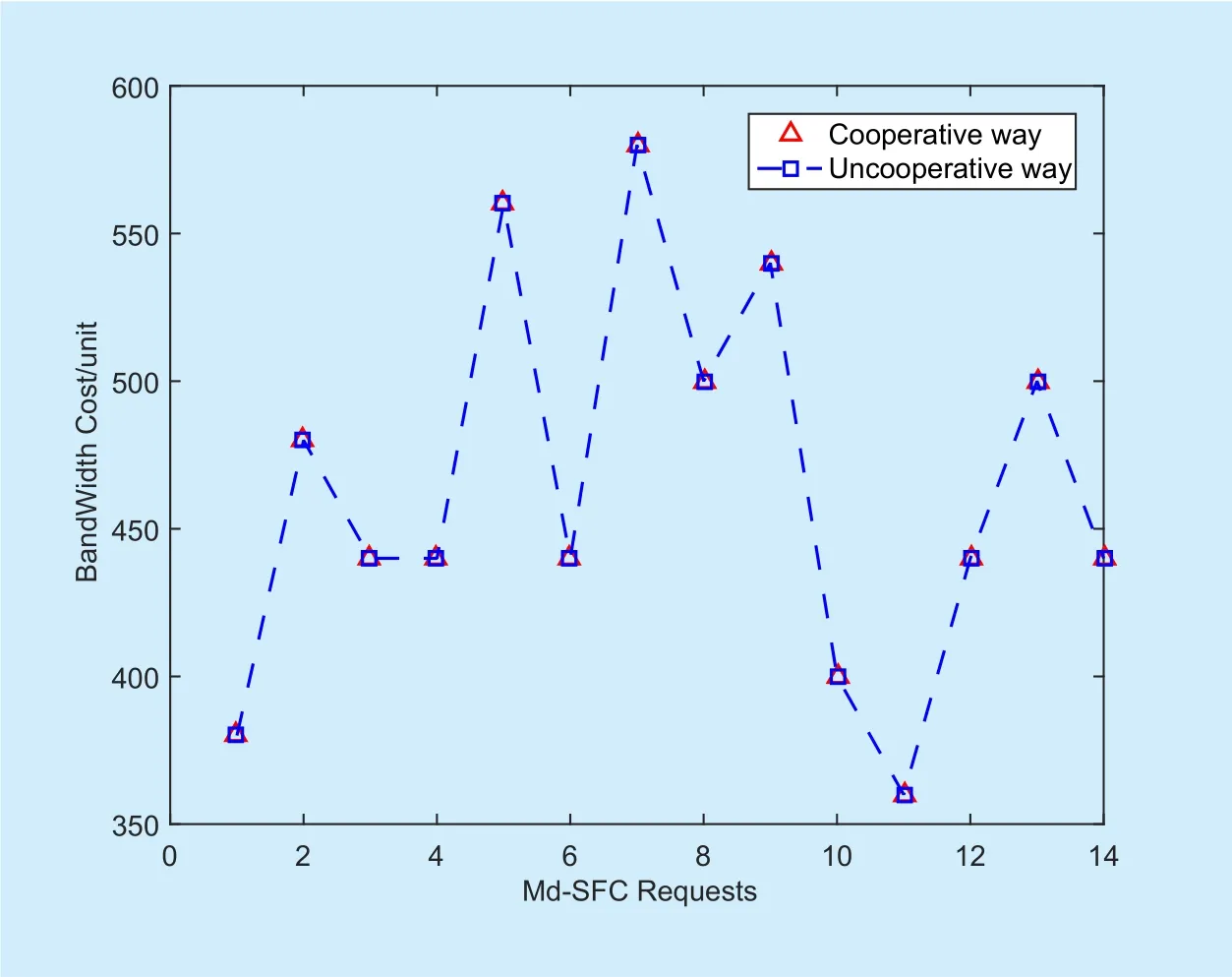
Fig. 13. Bandwidth cost comparison.
However, as figure 15 shows, the inter-domain path mapping delay of cooperative way is pretty small, as the master orchestrator does not search inter-domain paths for Sub-SFCs and just calculates the shortest path based on the multi-domain graph with 7 vertexes and 9 edges. In a cooperative way, computation load is distributed to each domain, so the total mapping delay is much less than the uncooperative way as figure 16 presents. Although we use the global multi-domain topology when calculating inter-domain paths for Sub-SFCs with the uncooperative way, it’s believed that the total mapping delay is still much larger when using a part of global topology.

Fig. 14. Maximum intra-domain mapping delay comparison.

Fig. 15. Inter-domain mapping delay comparison.
According to the simulation result, the cooperative inter-domain path calculation method is valid. If the master orchestrator has no enough computation ability or operators do not provide topology information, it’s a good choice to use the cooperative way, although it requires each intra-domain DoNFVO to execute more computation.
5.3 Performance comparison with random inter-domain link selection
Calculating paths to all edge nodes for each Sub-SFC increases intra-domain’s computation load and cost, but it is necessary. If an improper edge node is selected and reported to the master orchestrator, it may cause larger end-to-end delay or failure due to lack of a global view.
In order to compare end-to-end delay with and without global view, we do the same simulation in two different situations. In the first situation, we let DoNFVOs select edge nodes randomly for Sub-SFCs and are not aware of its inter-domain link’s bandwidth resources condition. In the other situation, we let DoNFVOs select edge nodes from available ones whose inter-domain links have enough bandwidth resources. In both situation, we let each DoNFVO make a wrong choice each time, which means an inter-domain link with no enough bandwidth or a longer inter-domain path from candidates will be selected for all Sub-SFCs.
Figure 17 shows the end-to-end delay comparison between this two situations and the cooperative way. In the first situation, the first 11 Md-SFC requests succeed and the 7th to 11th request use the satellite domain. The wrong choice of edge nodes leads to larger end-to-end delay and reduces the level of resources utilization as there still are available inter-domain links for the last 3 Md-SFCs. In the second situation, the first 6 Md-SFCs get the same result with the first situation, but the 7th to 11th one still use available inter-domain links of domain 3 and last 3 ones uses satellite domains. In the cooperative way, 4 Md-SFC requests (the 10-12th and 14th) use satellite domains as bandwidth demand is not satisfied when searching paths in domain 3. Most Md-SFC requests get less end-to-end delay compared with the second situation, except the 7th, the 10th and the 11th Md-SFC request.Figure 18 presents bandwidth cost comparison between different situations. In the first situation, except the 9th Md-SFC, others get the same or larger cost compared with the second situation. With the cooperative way, except the 7th and 9th Md-SFC requests, others have lower costs than the other two situations. Not all 14 Md-SFC requests get better result (less end-to-end delay and bandwidth cost) with the cooperate way, because the difference of mapping result (since the first Md-SFC) leads to different physical nodes and links’ resources usage and that affects mapping result of subsequent Md-SFC requests. In this paper,we only discuss how to calculate the shortest end-to-end path under the present condition of resources. Request online scheduling and resources reallocation based on propriety is a feasible way to distinguish traf fic and allocate resources reasonably.
VI. CONCLUSION
In this paper, we propose a horizontal-based multi-domain orchestration framework for Md-SFC in SDN/NFV-enabled satellite and terrestrial networks. In our framework, DoNFVOs located in different domains control and compute intra-domain Sub-SFCs. That different MdOs communicate with each other with messages can be regarded as a distributed approach. That the master MdO selects Sub-SFCs from candidate domains is a centralized computation. Compared with a naive uncooperative inter-domain path calculation method,the cooperative way has less mapping delay,and operators do not need to provide topology information as it distributes computing load to DoNFVOs. It also ensures the shortest available inter-domain path to be selected and the mapping result is the same with the uncooperative way.
ACKNOWLEDGEMENTS
This paper is supported by National High Technology of China (“863 program”) under Grant No. 2015AA015702, NSAF under Grant No. U1530118, NSFC under Grant No.61602030 and National Basic Research Program of China (“973 program”) under Grant No. 2013CB329101.
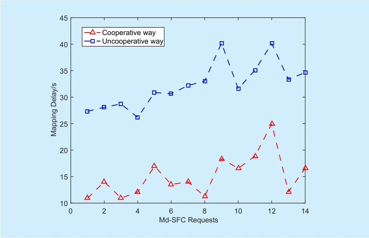
Fig. 16. Total mapping delay comparison.

Fig. 17. End-to-end delay comparison with random edge node selection.

Fig. 18. Bandwidth cost comparison with random edge node selection.
[1] R. Ferrús, et al., “SDN/NFV-enabled satellite communications networks: Opportunities, scenarios and challenges,” Physical Communication, Vol. 18, no. 2, 2016, pp. 95-112.
[2] R. Ferrús, O. Sallent, T. Rasheed, A. Morelli, H.Koumaras and G. Agapiou, “Enhancing Satellite & Terrestrial Networks Integration through NFV/SDN technologies,” IEEE COMSOC MMTC E-Letter, vol. 10, no. 4, 2015, pp. 17-19.
[3] L. Bertaux et al., “Software defined networking and virtualization for broadband satellite networks,” IEEE Communications Magazine, vol. 53,no. 3, 2015, pp. 54-60.
[4] W. Xia, Y. Wen, C. H. Foh, D. Niyato and H. Xie, “A Survey on Software-De fined Networking,” IEEE Communications Surveys & Tutorials, vol. 17,no. 1, 2015, pp. 27-51.
[5] ETSI GS NFV 002 V1.1.2: “Network Functions Virtualisation (NFV); Architectural Framework,”2014.
[6] J. Halpern and C. Pignataro, “Service Function Chaining (SFC) Architecture,” No. RFC 7665,2015.
[7] P. Quinn, T. Nadeau, “Problem statement for Service Function Chaining,” No. RFC 7498, 2015.
[8] P. Quinn and Elzur, U. “Network Service Header”, draft-ietf-sfc-nsh-12, February 2016.
[9] M. Boucadair, “Service Function Chaining (SFC)Control Plane Components & Requirements,”draft-ietf-sfc-control-plane-07 (work in progress), August 2016.
[10] ETSI GS NFV-MAN 001 V1.1.1: Network Function Virtualisation (NFV); Management and Orchestration, 2014.
[11] Rosa R V, Silva Santos M A, Esteve Rothenberg C. “MD2-NFV: The case for multi-domain distributed network functions virtualization,” Proc.IEEE International Conference and Workshops on Networked Systems, 2015.
[12] B. Sonkoly, R. Szabo, D. Jocha, J. Czentye, M.Kind and F. J. Westphal, “UNIFYing Cloud and Carrier Network Resources: An Architectural View,” Proc. IEEE GLOBECOM, 2015, pp. 1-7.
[13] A. Mayoral, R. Vilalta, R. Muñoz, R. Casellas and R. Martínez, “SDN orchestration architectures and their integration with Cloud Computing applications,” Optical Switching and Networking,Vol. 26, no. 2017, pp. 2-13.
[14] L. Liu, “SDN orchestration for dynamic end-toend control of data center multi-domain optical networking,” China Communications, vol. 12,no. 8, 2015, pp. 10-21.
[15] CJ. Bernardos, LM. Contreras and I. Vaishnavi, “Multi-domain Network Virtualization,”draft-bernardos-nfvrg-multidomain-01, October,2016
[16] D. Dolson, et al., “Hierarchical Service Function Chaining”, draft-ietf-sfc-hierarchical-01 (work in progress), September 2016.
[17] Li G, Li G, Li T, Xu Q and Zhou H, “Hybrid Hierarchical Multi-Domain Service Function chaining,”draft-li-sfc-hhsfc-02, April 2017.
[18] I. Trajkovska, et al., “SDN-based service function chaining mechanism and service prototype implementation in NFV scenario,” Computer Standards & Interfaces, vol. 54, no. 4, 2017, pp. 247-265.
[19] M. Yu, Y. Yi, J. Rexford and M. Chiang, “Rethinking virtual network embedding: substrate support for path splitting and migration,” Proc.ACM SIGCOMM Computer Communication Review, vol. 38 no.2, 2008, pp. 17-29.
- China Communications的其它文章
- Geometric Mean Decomposition Based Hybrid Precoding for Millimeter-Wave Massive MIMO
- Outage Performance of Non-Orthogonal Multiple Access Based Unmanned Aerial Vehicles Satellite Networks
- Outage Probability Minimization for Low-Altitude UAV-Enabled Full-Duplex Mobile Relaying Systems
- Optimal Deployment Density for Maximum Coverage of Drone Small Cells
- Energy Efficient Multi-Antenna UAV-Enabled Mobile Relay
- Energy-Efficient Trajectory Planning for UAV-Aided Secure Communication

