Numerical Simulation of Deterministic Freak Wave Based on Energy Distribution
GAO Ning-bo,YANG Jian-min,ZHAO Wen-hua,LI Xin
(1.State Key Laboratory of Ocean Engineering,Shanghai Jiao Tong University,Shanghai 200240,China;2.Faculty of Engineering,Computing and Mathematics,The University of Western Australia,35 Stirling Highway,WA6009,Australia)
Numerical Simulation of Deterministic Freak Wave Based on Energy Distribution
GAO Ning-bo1,YANG Jian-min1,ZHAO Wen-hua2,LI Xin1
(1.State Key Laboratory of Ocean Engineering,Shanghai Jiao Tong University,Shanghai 200240,China;2.Faculty of Engineering,Computing and Mathematics,The University of Western Australia,35 Stirling Highway,WA6009,Australia)
In this study,a theoretical freak wave sequence is numerically simulated and compared with the theoretical results.To accomplish this objective,velocity inlet method is applied.At the wave-maker boundary,linear velocity components are input,which takes no consideration of higher-order wave components.Numerical simulation in three different grid models is conducted to determinate which model is efficient as well as being capable to track the free surface.As Fast Fourier Transformation(FFT)can not reflect the temporal-frequency of the freak wave,thus wavelet analysis is introduced to investigate the energy of the wave package during the wave propagation.Comparison of wavelet transform of the freak wave recorded in North Sea and present freak wave is made.
Navier-Stokes equations;freak wave;wave-wave interaction;wavelet analysis
0 Introduction
In the past decades,freak wave has been affirmed by more and more observations and reports gathered by ships and oil platforms,and heated researched in oceanography and marine engineering.It comes from nowhere and disappears without a trace.Considering their unexpectedness and anomalous features,these billows can pose destructive damages on ships and marine structures despite their low probability of occurrence[1-2].
Both the definition as well as the formation mechanisms of freak waves are still under intensive investigations.Commonly,researchers tend to accept this freak wave definition that the maximum wave height is at least two times of the significant wave height(Hmax≥2HS).Kharif and Pelinovsky[3]summarized the mechanisms of freak waves and classified them as two catalogues:linear theories and nonlinear theories.Linear dispersive focusing theory has been widely used to model freak waves experimentally and numerically.This can be accomplished by the focusing of numbers of component waves to form a localized extreme wave.Baldock,Swan et al[4]experimentally designed focused wave groups using many superimposed regular wave trains through modulating the initial phase,and examined the effects of nonlinear wave-waveinteractions on the structure of unidirectional wave groups.
Kjeldsen[5]and Koola et al[6]had given the details of the generation of freak waves,and Sundar[7]applied their method to conduct a wave tank experiment to investigate dynamic pressure on inclined cylinders due to freak waves.Kriebel[8]improved the linear superposition model by combining a transient wave group and a random wave series.Based on this model,an experiment was conducted in a wave flume,and the particle horizontal velocity field was compared with those of the equivalent-size laboratory Stokes 5th-order wave,and it was found that the peak particle velocity of the freak wave is 2.4 times than that of the laboratory Stokes 5th-order wave[9].Wavelet transform based on coherence analysis has been applied to a laboratory-generated freak wave and its impact forces on a vertical truncated cylinder[10].Cui et al[11]numerically simulated the freak wave based on linear dispersive focusing mechanism and investigated the effects of uneven bottom topography on freak wave transformation and energy transfers.Zhao and Hu[12]conducted numerical and experimental study on a 2-D floating body under extreme wave conditions which is achieved by combining regular wave and focused wave.
Although some nonlinear theories have been put forward to explain the formation of freak waves,like nonlinear cubic Schrodinger equation[13],the Majda-McLaughlin-Tabak(MMT)equation[14],it is not easy to use those nonlinear theories to simulate freak wave experimentally and numerically.Moreover,most experimental wave tanks are based on linear transfer function to get wave-maker control signal[15].In general,freak waves are rare events embedded in random seaway.Linear dispersive focusing method makes it unnecessary to wait for rare events by intentionally selecting a suitable phase shift,and reproduces a deterministic wave sequence of waves converging at preset site[16].
In this paper,a theoretical wave sequence which satisfies the definition of freak wave that maximum wave height is at least twice times of the significant wave height is chosen as the target wave.Velocity inlet method is applied to generate this freak wave in a numerical wave tank.The propagation of the freak wave is investigated.This paper is organized as follows.In Chap.1 the numerical model is presented.A theoretical freak wave series is defined in Chap.2,and it is reproduced numerically in Chap.3.Moreover,wavelet transform method is applied to investigate the time-frequency characteristics of the freak wave.Finally,some conclusions are drawn in Chap.4.
1 Mathematical model
1.1 Governing equations
A commercial CFD package FLUENT is used in this paper.The governing equations that need to be solved by the FLUENT solver are the mass continuity equation which are expressed as

and the Navier-Stokes equations which are given as

where u and v are the components of the velocity vector V→in the x and y directions,respectively;ρ is the fluid density;μ is the dynamic viscosity and t is the time;Si,with i being x and y,is the source terms acting on i-direction,in which the gravity forces are included.
In order to trace the position of the free surface,the volume of fluid[17]method is applied.This technique was also employed by Liang et al[18].This method adds another governing equation of fluid fraction αq(x,y, )t,given by

where,aq=0:the cell is empty(of the qthfluid);aq=1:the cell is full(of the qthfluid)0<αq<1:the cell contains the interface.Here,aq=0.5 is regarded as the free surface and its vertical coordinate which is given as surface elevation time history is extracted at the position of the wave gauges for every time step.
In this study,laminar model is adopted.Pressure-velocity terms are calculated using PSIO algorithm.The convection and diffusion terms are discretized using Second Order Upwind scheme.Geo-reconstruct scheme is employed to track the free surface.
1.2 Numerical wave tank model
The detailed configuration of the geometric model is shown in Fig.1.Coordinate origin O locates at the left side of the wave tank bottom.The wave tank length is 15 m,with a 4m length wave absorbing zone.The height of this numerical model is 1.2 m and the initial water depth is 0.9 m.The preset position of wave focusing is 7 m downstream of the left velocity inlet boundary.The distances to other wave gauges,measured from the left boundary are detailed listed in Tab.1.

Fig.1 Configuration of numerical wave tank
Structured grids are used to get smooth free surface in this study.For saving calculating resources as well as improving accuracy,meshes in the vicinity of static free surface are re-fined,together with coarse mesh is used in the wave absorbing zone.As to grid convergence,Paulsen et al[19]has pointed out that 10~15 points per wave height(p.p.w.h)is enough for regular wave simulation.In this study,the target wave is one theoretical freak wave sequence which does not have characteristic wave height like regular wave.Here,the number of point per freak wave height(p.p.f.w.h)is chosen as the criterion.

Tab.1 Distances of wave gauges to left-hand boundary
The left-hand boundary is velocity inlet,where the horizontal and vertical velocity components are defined together with the volume fraction of air and water.The top boundary is defined as pressure inlet which permits fluid flow through the boundary.The bottom and the righthand of the model are non-slip boundary.At the wave absorbing zone,the dynamic viscosity of the water fraction increases linearly from 1.003×10⁻³Pa.s to 800.0 Pa.s as the following formula

where,xLand xRare the left and right coordinates of the wave damping zone,respectively.
2 Theoretical freak wave sequence
In this section,a theoretical freak wave is embedded into a random wave sequence,which is achieved by separating the total wave energy into two parts with one part of the energy going into transient wave and the other part going into the underlying random wave[20].The wave elevation can be expressed as

where N is the number of component wave;a1iand a2iare the amplitude of the random and transient waves which are calculated askiand ωiare the wavenumber and frequency of the ith component wave;is the average value of the angular frequency interval which means;εiis the phase of the wave components which is a random number in the interval[0,2 ]π ;xcand tcrepresent the focus point and time,respectively,and S( ωi)is the target wave spectrum:JONSWAP spectrum which is expressed as

where α=0.062 4/[0.230+0.033 6γ-0.185( 1.9+ γ )-1];H1/3and TPare significant wave height and peak period,respectively;γ is the peakness parameter(the average value of γ is 3.3);σ is the shape parameter which σ=0.07 if f≤fPand σ=0.09 if f>fP;and ω=2πf.
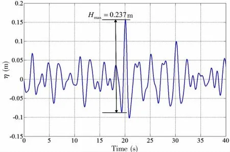
Fig.3 Theoretical freak wave sequence
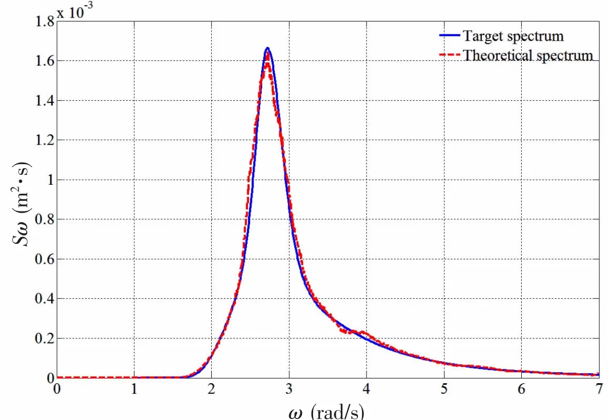
Fig.4 The comparison of wave spectrums
Here,the significant wave height equals 5.9 cm,and peak period is 2.31 s.For keeping the statistics property of the wave train,only a small part of the total energy is used to gener-ate transient wave,which means P1=0.95 and P2=0.05.The theoretical freak wave sequence is shown in Fig.3.The comparison of target wave spectrum and theoretical spectrum is presented in Fig.4 which shows that the agreement goes quite well.
3 Numerical results
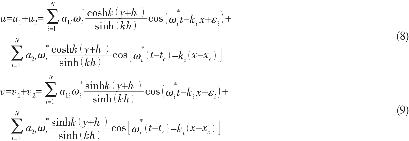
In this study,velocity inlet method is employed to generate waves.The horizontal and vertical velocity are defined together with the volume fraction of air and water.The horizontal and vertical velocity components are written as:
It can be drawn from Fig.3 that the freak wave height is 0.237 m and the wave crest is 0.155 m.Three grid models are applied here,and the detailed information is listed in Tab.2.

Tab.2 Summary of grid model set-up
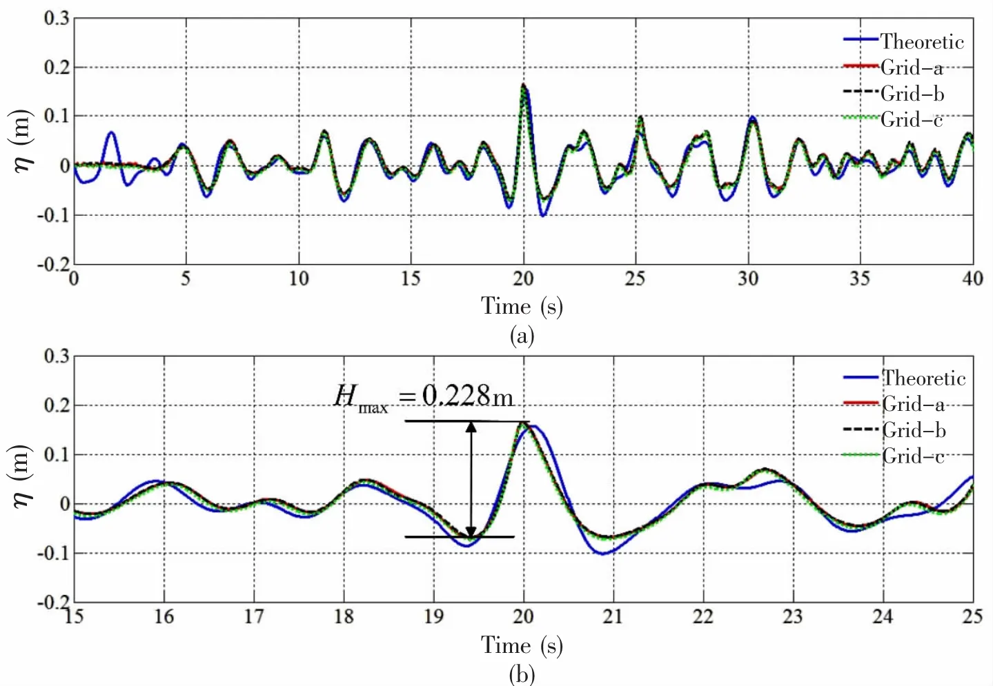
Fig.5 Comparison of theoretic results and numerical results in three grid models
Fig.5 shows the comparison of theoretical freak wave train and numerical results in three grid models.It can be concluded that it presents little difference for three models which means 25 points per freak wave height is enough to trace the free surface.Moreover,the numerical results agree well with the theoretical sequences except that the wave trough is much shallower than that of theoretical results.In order to reflect the propagation of the freak wave,wave elevations at several locations are presented in Fig.6.Before freak wave occurring,there has been an extreme wave envelope ahead of the target position.The power spectrum of the numerical wave trains at three locations is determined via a fast Fourier transform(FFT)which is shown in Fig.7 and it gives a clue that freak wave’s occurrence does not change the power spectrum of the background wave state.
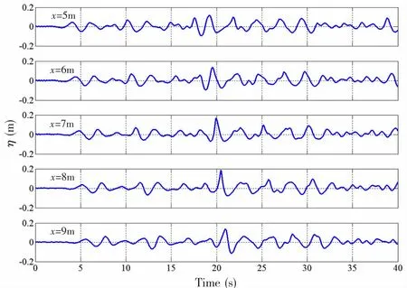
Fig.6 Wave elevations at five different locations(x=5 m,x=6 m,x=7 m,x=8 m,x=9 m)

Fig.7 Wave spectrum at three locations(x=5 m,x=7 m,x=9 m)
Unlike fast Fourier transformation,wavelet method has been applied in the time-frequency characteristics analysis on freak waves[21].The priority to apply continuous wavelet transform(CWT)method is to determinate window function.Here,Morlet wavelet[22]is selected as the window function and expressed as

where t is the time;ω0is the peak frequency of the wavelet,usually chosen to be 6.0 to meet the admissible condition.
The continuous wavelet transform of a discrete wave train η()
tis defined as the convolution of η(t)with a scaled and translated version of ψ0(t)

where the asterisk means the complex conjugate ands is the wavelet scale.
From Fig.8,it is obvious that the wave energy is focusing during freak wave occurrence.Before freak wave occurring,the wave energy is smaller,and it seems no premonition to explain that the freak wave will happen which agrees with the fact that freak waves sometimes appear suddenly in calm sea states.Interestingly,we can see that the wavelet energy of the freak wave is at least 2 times of that of normal waves.
Considering that the freak wave in this study is only theoretically defined,there is still doubt that whether the definitional freak wave can reflect the characteristics of the measured freak wave in the real sea state or not,even though the defined wave sequence here satisfies the freak wave definition.Following,the comparison of wavelet energy of recorded field wave train and the defined freak wave is conducted.New Year Wave is world-renowned freak wave which was recorded in North Sea[1].In order to conduct the wavelet energy comparison,the recorded New Year Wave is transformed into model scale which the scale ratio is 100.Fig.9 shows the time history of New Year Wave in model scale.
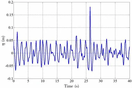
Fig.9 New Year Wave recorded in North Sea
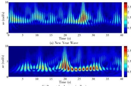
Fig.10 Comparison of wavelet energy of New Year Wave and present freak wave
From Fig.10(a),we can find that most energy is flocked around 26 s when the New Year Wave occurring,and it means that freak wave owns enormous energy and can pose destructive damages on ships and marine structures.Comparing Fig.10(a)and Fig.10(b),it can be concluded that the defined theoretical freak wave shares the similar time-frequency characteristics with the recorded New Year Wave,which means that the above numerical model can be applied to generate freak wave.This serves as a strong basis for the following research on freak wave impact on marine structures.At last,the wavelet transform is an efficient method which can be used to reveal the detailed information on the time-frequency characteristics of the freak wave train.
4 Conclusions
In this paper,velocity inlet method is applied to simulate water waves in a numerical wave tank based on the commercial CFD software package FLUENT.A wave sequence which satisfies the freak wave definition is numerically simulated and compared with the theoretical freak wave train which proves that this numerical model is feasible to simulate definitional freak wave series.Fast Fourier Transform is employed to analyze the numerical results,and no useful information is obtained which proves the FFT method is not suited for non-stationary series like freak wave sequence.Continuous wavelet transform is applied to reveal the timefrequency characteristics of the freak wave.During the freak wave occurring,the wave energy bumps up severely from the mild sea state which agrees with the fact that freak wave occurs suddenly leaving no rescue time for staffs on ships and offshore structures.By comparing the wavelet transform of the recorded New Year Wave and the definitional freak wave,we find that they both share similar time-frequency characteristics which means the definitional freak wave can be regarded as one prototype of real freak wave,and this lays a solid foundation for the following research on freak wave impact on marine structures.
Acknowledgement
The authors would like to thank Dr.Sverre Haver from Statoil for kindly providing the New Year Wave sequences.This work is supported by the National Nature Science Foundation of China(Grant No.51239007).The 3rd author is supported by the Shell EMI offshore engineering initiative at University of Western Australia.These forces of support are gratefully acknowledged.
[1]Haver S.A possible freak wave event measured at the Draupner jacket,January 1 1995[C].Proc Rogue Waves 2004,2004.
[2]Nikolkina I,Didenkulova I.Catalogue of rogue waves reported in media in 2006-2010[J].Natural Hazards,2012,61(3):989-1006.
[3]Kharif C,Pelinovsky E.Physical mechanisms of the rogue wave phenomenon[J].European Journal of Mechanics-B/Fluids,2003,22(6):603-34.
[4]Baldock T,Swan C,Taylor P.A laboratory study of nonlinear surface waves on water[J].Philosophical Transactions of the Royal Society of London Series A:Mathematical,Physical and Engineering Sciences,1996,354(1707):649-76.
[5]Kjeldsen S P.Breaking waves[M].Springer,1990.
[6]Koola P,Sundar V,Kaldenhoff H,et al.Pressure distribution around cylinders due to freak waves[C]//Proc.Int.Conf.in Ocean Engineering.Madras,India,1996:189-194.
[7]Sundar V.Dynamic pressures on inclined cylinders due to freak waves[J].Ocean Engineering,1999,26(9):841-63.
[8]Kriebel D L.Efficient simulation of extreme waves in a random sea[C]//Proceedings of the Rogue Waves 2000 Workshop.Brest,F,2000.
[9]Kim N,Kim C H.Investigation of a dynamic property of Draupner freak wave[J].International Journal of Offshore and Polar Engineering,2003,13(1):38-42.
[10]Kwon S H,Lee H S,Kim C H.Wavelet transform based coherence analysis of freak wave and its impact[J].Ocean Engineering,2005,32(13):1572-1589.
[11]Cui C,Zhang N C,Yü Y X,et al.Numerical study on the effects of uneven bottom topography on freak waves[J].Ocean Engineering,2012,54:132-141.
[12]Zhao X,Hu C.Numerical and experimental study on a 2-D floating body under extreme wave conditions[J].Applied O-cean Research,2012,35:1-13.
[13]Akhmediev N,Ankiewicz A,Taki M.Waves that appear from nowhere and disappear without a trace[J].Physics Letters A,2009,373(6):675-678.
[14]Pushkarev A,Zakharov V E.Quasibreathers in the MMT model[J].Physica D:Nonlinear Phenomena,2013,248:55-61.
[15]Clauss G F,Schmittner C E,Hennig J.Systematically varied rogue wave sequences for the experimental investigation of extreme structure behavior[J].Journal of Offshore Mechanics and Arctic Engineering,2008,130(2):021009.
[16]Clauss G,Klein M.The New Year Wave in a seakeeping basin:Generation,propagation,kinematics and dynamics[J].O-cean Engineering,2011,38(14):1624-39.
[17]Hirt C W,Nichols B D.Volume of fluid(VOF)method for the dynamics of free boundaries[J].Journal of Computational Physics,1981,39(1):201-25.
[18]Liang X,Yang J,Li J,et al.A numerical study on local characteristics of predetermined irregular wave trains[J].Ocean Engineering,2011,38(4):651-657.
[19]Paulsen B T,Bredmose H,Bingham H B,et al.Forcing of a bottom-mounted circular cylinder by steep regular water waves at finite depth[J].Journal of Fluid Mechanics,2014,755:1-34.
[20]Cui C,Zhang N,Kang H,et al.An experimental and numerical study of the freak wave speed[J].Acta Oceanologica Sinica,2013,32(5):51-6.
[21]Lin E B,Liu P C.A discrete wavelet analysis of freak waves in the ocean[J].Journal of Applied Mathematics,2004,2004(5):379-94.
[22]Torrence C,Compo G P.A practical guide to wavelet analysis[J].Bulletin of the American Meteorological Society,1998,79(1):61-78.
基于能量分配的特定畸形波序列的数值模拟
高宁波1,杨建民1,赵文华2,李 欣1
(1.上海交通大学 海洋工程国家重点实验室,上海200240;2.澳大利亚珀斯西澳大利亚大学工学院,WA6009澳大利亚)
文章对一个理论畸形波序列进行了数值模拟并且将数值结果与理论值做了对比。采用速度入口方法以实现波浪模拟。在造波边界处不考虑高阶波浪成分,只输入线性波浪速度。分别采用三种不同分辨率的网格进行数值模拟,以找到足够有效捕捉自由面的网格模型。考虑到快速傅里叶变换不能反映畸形波的时频特征,因而引入小波变换研究畸形波传播过程中的能量变化。最后比较了北海实测畸形波和文中理论畸形波小波变换的差异。
N-S方程;畸形波;波—波相互作用;小波分析
O353.2
A
国家自然科学基金资助项目(51239007)
高宁波(1988-),男,上海交通大学博士研究生;
杨建民(1958-),男,上海交通大学教授,博士生导师;
赵文华(1986-),男,博士,澳大利亚珀斯西澳大利亚大学工学院;
李 欣(1975-),女,上海交通大学副教授。
O353.2 Document code:A
10.3969/j.issn.1007-7294.2017.12.001
date:2017-09-13
Supported by the National Natural Science Foundation of China(Grant No.51239007)
Biography:GAO Ning-bo(1988-),male,Ph.D.candidate,E-mail:jiaxiang3708@sjtu.edu.cn;
YANG Jian-min(1958-),male,professor/tutor,E-mail:jmyang@sjtu.edu.cn.
1007-7294(2017)12-1449-11
- 船舶力学的其它文章
- Low-Cycle Fatigue Crack-Propagation Behavior for Ship Cracked Plate Considering Accumulative Plastic Damage
- Method of Estimating the Effect of Marine Fouling on Frictional Resistance of Ships
- Evaluation of Viscous Effect on Wave Excitation Force of a Vessel with Transom Stern
- Numerical Predictions of the PPTC Propeller Tip Vortex Cavitation in Uniform Flow
- Enhanced Extinction Curve Method for Roll Damping Estimation
- Algorithm Simulation of Ship Dynamic Positioning Using Adaptive Fading Memory Filter

