Evaluation of Viscous Effect on Wave Excitation Force of a Vessel with Transom Stern
SUN Xiao-shuai,DONG Wen-cai,YAO Chao-bang
(Department of Naval Architecture Engineering,Naval University of Engineering,Wuhan 430033,China)
Evaluation of Viscous Effect on Wave Excitation Force of a Vessel with Transom Stern
SUN Xiao-shuai,DONG Wen-cai,YAO Chao-bang
(Department of Naval Architecture Engineering,Naval University of Engineering,Wuhan 430033,China)
The accurate prediction of wave excitation force is essential for the prediction of ship motions in waves.The wave excitation force of a ship with transom stern in wave is studied here by two different calculation methods:complicated CFD simulation based on an unsteady RANS approach and boundary element method based on three dimensional translating and pulsating Green Function(3DTP).Comparisons are made between the experimental data and numerical results to validate each numerical method.The viscous effect on wave excitation force is investigated by taking advantage of CFD.The results indicate that both RANS method and 3DTP method give good prediction of wave excitation force,while the RANS method gives slightly better result in the long wave range.The viscous effect accounts for a large component of the roll moment in oblique wave.
wave excitation force;RANS;viscous effect;three dimensional translating and pulsating Green Function
0 Introduction
The accurate solution of diffraction problem of vessel with forward speed is critical for the prediction of ship motions in waves.At the present time,both model experiments and numerical methods are utilized to deal with the diffraction problem.As for the traditional model experiment,it is still difficult to monitor the complex flow field around the ship due to limitation of instrument and technology in measurement[1].
The numerical methods include potential theory and viscous theory.A lot of efforts have focused on using both linear and nonlinear potential flow for seakeeping problems[2-5].The use of 3D panel method to study seakeeping problem is becoming more common in recent year.However,the potential theory cannot take the effect of viscosity into consideration,which results in poor ability to predict strong nonlinear motions[6].To deal with this situation,Chen&Lu[7],Dutykh[8]added viscous effect into potential theory,but it has not been validated.
As high-performance computers become more powerful and more accessible,CFD-based RANS methods are rapidly gaining popularity for seakeeping problems.Carrica[9]developed asoftware called CFDSHIP IOWA based on RANS to solve diffraction from with viscosity.Wilson[10]carried out CFD simulations to predict the pitch and heave transfer functions of the S175 ship in head wave.Fang[11]built a numerical wave tank based on RANS and computed the wave forces on forwarding Wigley hull in both head wave and oblique wave.Guo[12]and Kim[13]utilized two different solvers respectively based on RANS to predict the motions and added resistance of KVLCC2,which indicated good agreement with the experimental results.
To evaluate the effect of viscosity on wave excitation force,the wave excitation of a ship with transom stern in wave is studied here numerically.A numerical wave tank is established based on an unsteady RANS approach and Volume of Fluid(VOF)method,by utilizing the User Defined Function(UDF)in the commercial CFD software Fluent.The boundary element method based on three dimensional translating and pulsating Green Function(3DTP)is applied here to solve the diffraction problem to make comparison with other methods.By taking the advantage of CFD,the viscous effect on wave excitation force is investigated based on RANS.Comparison of different methods indicate that both RANS method and 3DTP method give good prediction of wave excitation force,while the RANS method gives slightly better result in the long wave range.The viscous effect accounts for a large component for the roll moment in oblique wave.
1 Ship model
The model in the present work is a hull with bulbous bow,flare side wall and transom stern.The model is a bare hull without rudder or propeller.The main parameters of the hull are given in Tab.1 and the side view is shown in Fig.1.
The experiments are carried out at three different Fn in head waves with wave amplitude A/L=0.008 67 and λ/L=0.578~3.467 as shown in Tab.2.The numerical calculations including both CFD and BEM are also carried out at one velocity in oblique wave( β=150°).
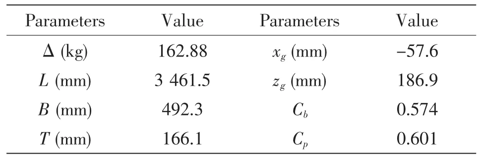
Tab.1 Main parameters of the hull model


Tab.2 Experimental and numerical test cases
2 CFD simulation
2.1 Governing equations
The viscous flow control equations contain continuity equations and momentum equations,which may be written as follows:

where ρ is the fluid density, μ is the fluid viscosity degree,p is the static pressure,fiis the mass force,uiand ujare the velocity components.
To model the viscous fluid flow,the solver employed use a finite volume method which discretizes the integral formulations of the Navier-Stokes equations.
The turbulent model selected in this study is a RNG k-ε model,which is shown as:
Turbulent fluctuation kinetic energy equation(k equation)is:

Turbulent energy dissipation rate equation(ε equation)is:

The free surface is captured by the ‘Volume of Fluid’ (VOF)method which is shown as follows:

where q=1,2,a1and a2refer to the volume of air-phase and water-phase.
The second order upwind scheme is adopted to discretize the momentum equation and the turbulent model.The volume fraction of phase is discretized with Geo-reconstruct.The couple method of velocity and pressure is chosen as SIMPLEC.
2.2 Meshes and boundary conditions
The calculation field meshes and boundary conditions are shown in Fig.2 and Fig.3.In the process of grip generation,the practical guidelines recommended by the International Towing

Fig.2 Flow field
Tank Conference recommended are followed.The total length of the calculation field changes with the wave length λ.The entrance is 1λ ahead of the bow and is set as velocity-inlet which is defined by the User Defined Function(UDF).It is divided into upper and lower layers along the waterline.While the upper layer is air,the lower layer is water.The export is 3λ behind the stern and is set as pressure-out,where the hydrostatic pressure increases with the water depth.The side face and bottom face are set as velocity-inlet and are one hull length L away from the hull surface.The length of the damping zone is 1.5λ.The hull surface is set as wall,which meets the impenetrable condition and no-clip condition.The direction of gravity is perpendicular to the static water.
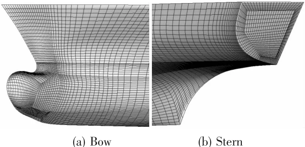
Fig.4 Meshes of the hull
The calculation field is dispersed by full structured grid in software ICEM.The total number of calculation field grid is around 1.5 million.An O-block is introduced around the hull surface to refine the grids in the boundary layer to obtain the complex flow features.Besides,the grids near the waterline are also refined to capture precise information about the free surface.A wall function is used to model the flow around the hull and y+at the hull surface is kept in the range of 40 to 200 except in a limited area close to the bow and stern.The grid of the damping zone increases along the wave spreading direction to provide numerical damping.
2.3 Numerical wave tank
The numerical wave tank that can precisely generate the required wave is the basis to solve the diffraction problem.It consists of wave-generating zone,working zone and damping zone,which is depicted in Fig.5.
The boundary simulation by inputting the velocity function of wave at the entrance is utilized in this essay.In the theory of infinite linear wave,the wave surface and velocity function of regular wave in the fixed coordinate system are shown as follows:
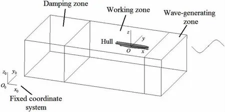
Fig.5 Numerical wave tank

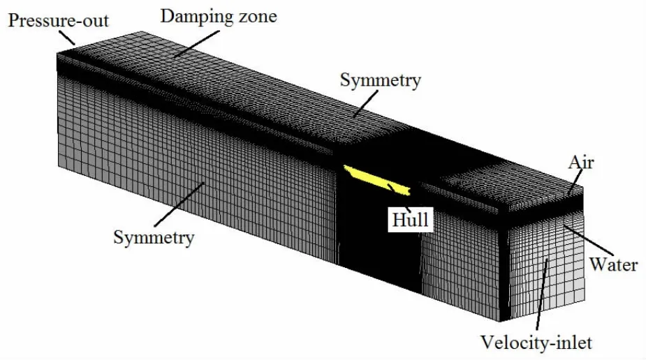
Fig.3 Meshes and boundary conditions

where A is the amplitude,k0is the wave number,ω0is the wave frequency,O0x0is the wave propagate direction,O0y0is the transverse direction,O0z0is the fluctuant direction.
In the reference coordinate system Oxyz that move with the hull at the forward velocity U0,the wave surface and velocity function of regular wave are shown as follows:

where ωeis the encounter frequency,β is the wave to course angle.ωe=ω0-kUcosβ.
A damping zone extends 1~2 times of wavelength is set before the output boundary to eliminate wave reflection and secondary reflection.In order to maintain the continuity of horizontal flow,the damping is just applied to the vertical velocity.The damping coefficient is

where γ is the control parameter of damping coefficient,xsand xeare the x coordinate of the start point and end point of the damping zone,zband zfare the z coordinate of the damping zone bottom and free surface.
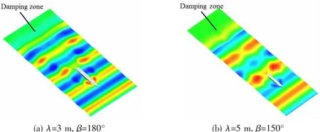
The Fig.6 indicates the wave surface of the regular wave comes from two different directions(λ=6 m,hw=0.1 m).

Fig.6 Simulation of regular wave(λ=6 m,hw=0.1 m)
A wave surface monitor is set six miters after the inlet boundary.The comparison of time history of wave elevation between the numerical wave and the theory wave is shown in Fig.7.As depicted in Fig.7,the results match well with each other,which verifies the wave generat-ing method.Besides,the numerical wave trough is smoother than the theory one,which indicts the effect of nonlinearity.
The wave pattern of the NWT free surface at one certain time after the computation becomes steady is shown in Fig.8.While no attenuation of the wave height is found along the wave propagate direction before the damping zone,the wave surface becomes smooth in the damping zone.Thus the effectiveness of the damping absorption method is demonstrated.
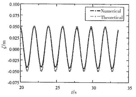
Fig.7 Time history of wave elevation at point x=6 m from inlet
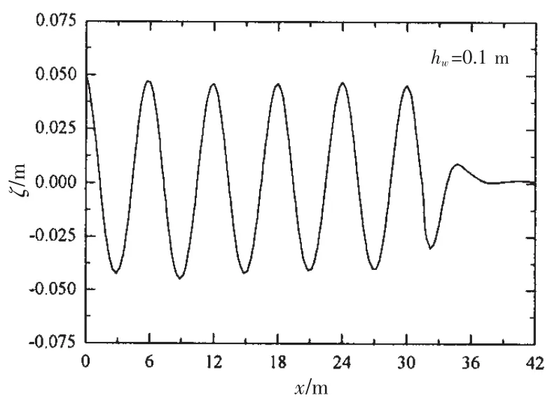
Fig.8 The wave pattern of NWT free surface
3 Boundary element method based on 3DTP
The Green function method has the advantages that it requires distribution of singularities on only the wetted hull surface and it satisfies the radiation condition automatically.In the present work,the boundary element method based on the Bessho form three-dimensional translating and pulsating Green function(3DTP)in frequency domain is utilized to predict the wave excitation force,since the integration of this Green function and its derivatives over an elementary panel or the waterline segment can be expressed analytically.
Single expression of Bessho form translating-pulsating source Green function can be expressed as:

where,

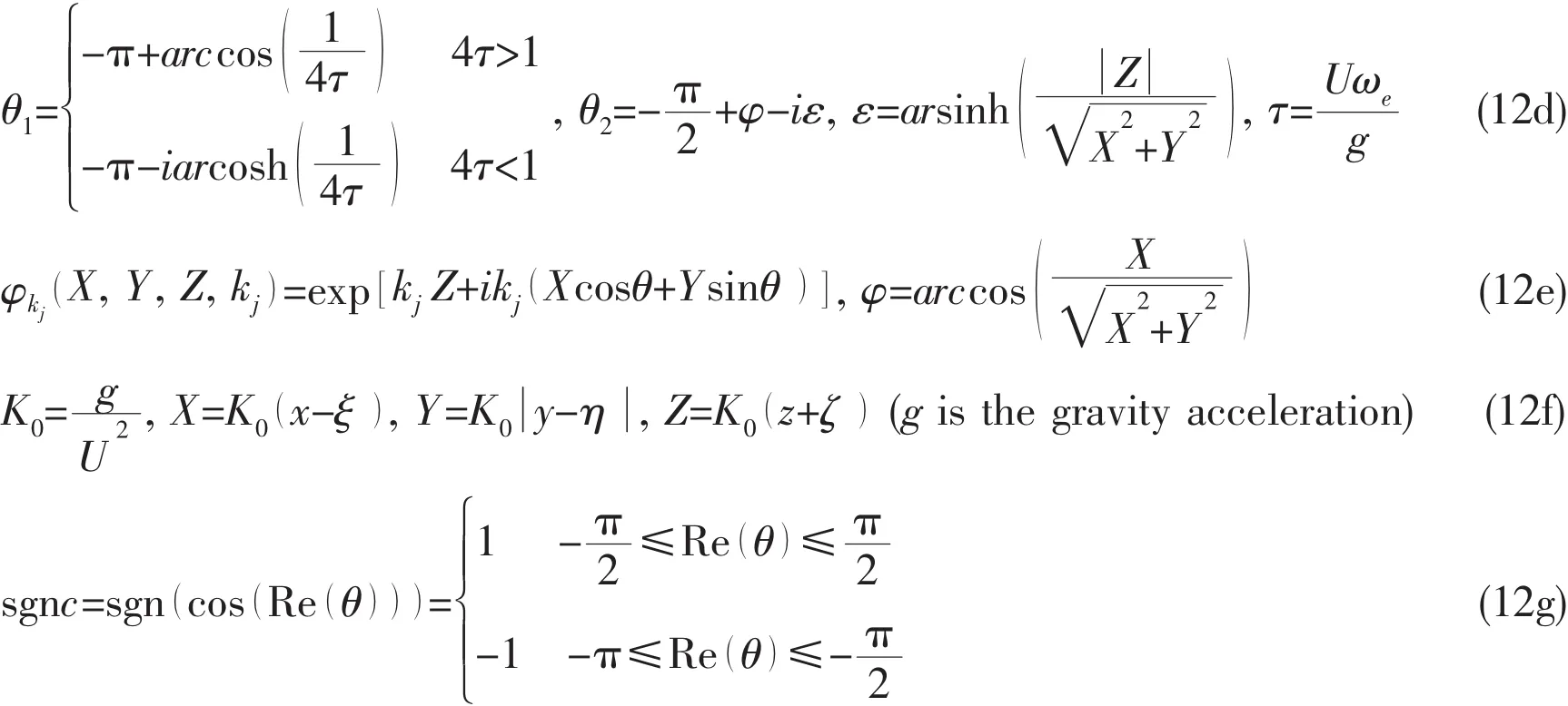
The analytical quadrature of this Green function over a panel and a waterline segment can be expressed as,

With Qlvertices of panelnd Slarea of triangle
Based on the variable substitution and the steepest descent integration method,a fast numerical calculation method for G,ISand ILcan be obtained[5].
4 Discussion of results
4.1 Wave pattern of CFD simulation
The flow field with free surface around the hull is depicted in Fig.9 at Fn=0.175.The wave motivated by the advancing hull,the incident wave,the radiation wave and the diffraction waveinterfere with each other,while in the damping zone the wave surface becomes smooth.
4.2 Wave forces
The time history of the wave forces of the advancing hull in head regular wave based on RANS is depicted in Fig.10(λ=6 m,Fn=0.175).

Fig.10 Wave forces in head wave(λ=6 m,Fn=0.175)
The wave forces in wave are converted into non-dimensional form in order to compare with the experimental result.The non-dimensional function is shown as follows:

where ωeis the encounter frequency,F1a,F2a,F3a,F4a,F5aand F6aare the first order amplitudes of surge,sway,heave,roll,pitch and yaw wave force time history,respectively.
The non-dimensional wave forces of the hull model in head regular waves at different Fn are shown in Figs.11~13.Overall,the wave forces based on RANS and 3DTP respectively are in good agreement with experiment.
The surge forces based on RANS are slightly larger than the 3DTP.In short waves,the 3DTP seems to give a better prediction.While in long waves,RANS results indicate better agreement with the EFD.As for the heave force,good agreement with all methods can be found at Fn=0.153 and Fn=0.175.When comes to the pitch moments,it indicates almost the same trend as the heave forces.The results based on RANS give slightly better prediction in the long waves.
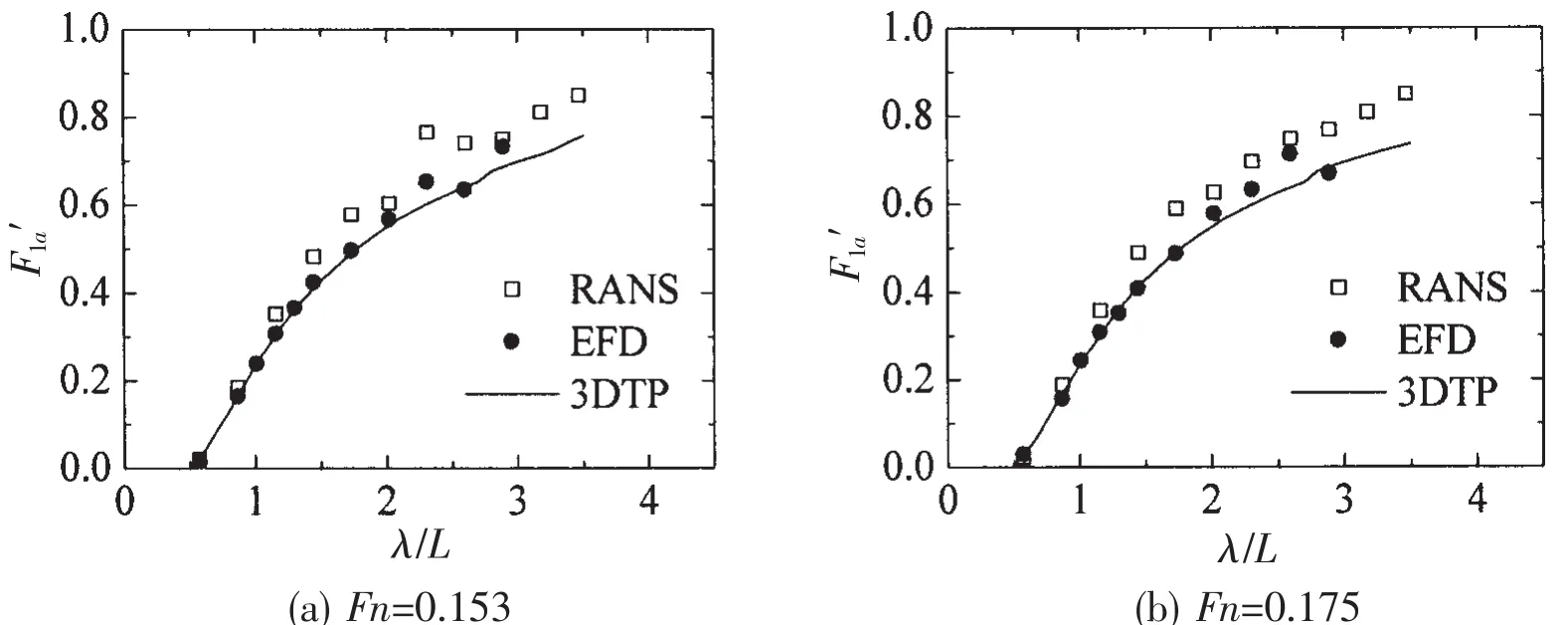
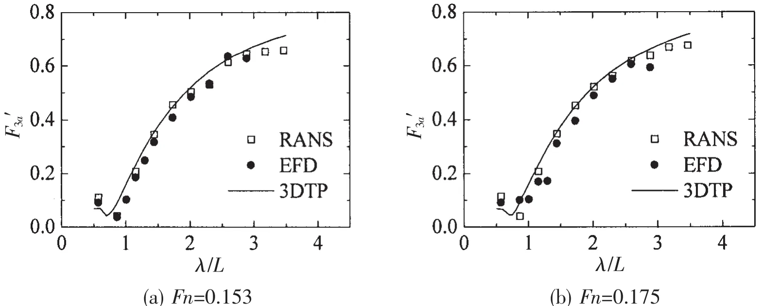
Fig.12 Heave forces in head waves at different Fn
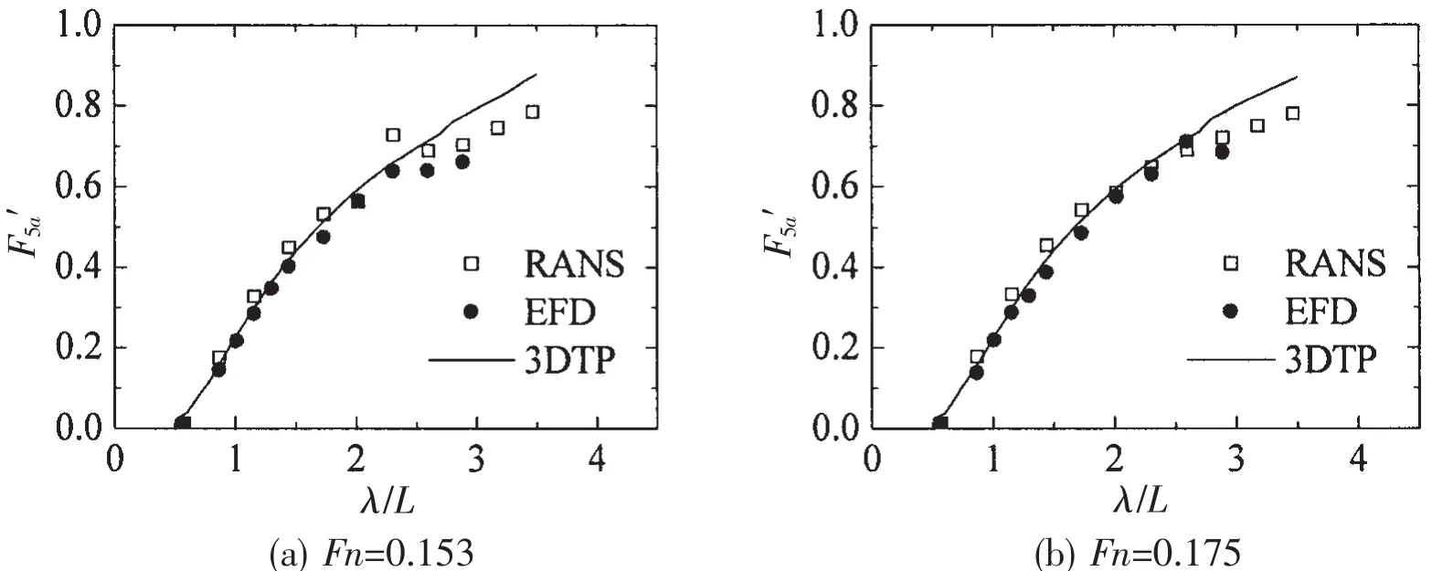
Fig.13 Pitch moments in head waves at different Fn
The time history of wave forces of the advancing hull in oblique regular wave at Fn=0.175 is given in Fig.14(λ=7 m,β=150°).It can be obviously seen that the roll moment and yaw moment contain second order force.However,to make comparison with the result from potential theory,only the first order amplitude is paid attention to.

Fig.14 Time histories of wave forces in oblique wave at Fn=0.175(λ=7 m,β=150°)
The non-dimensional wave forces of the hull model in oblique regular waves based on RANS and 3DTP are shown in Fig.15(Fn=0.175, β=150°).Good agreement can be found in the sway force,heave force and pitch moment.The surge force based on RANS outnumbers that based on 3DTP,which is similar like what we found in the head wave.As for roll moment and yaw moment,significant difference could be found in the long wave.The roll moment based on RANS outnumbers that based on 3DTP by a maximum of 14.7%at λ/L=2.6,while the yaw moment based on RANS overweighs that based on 3DTP by a maximum of about 60%at λ/L=3.178.Whether this is due to the viscous effect will be investigated in the next section.
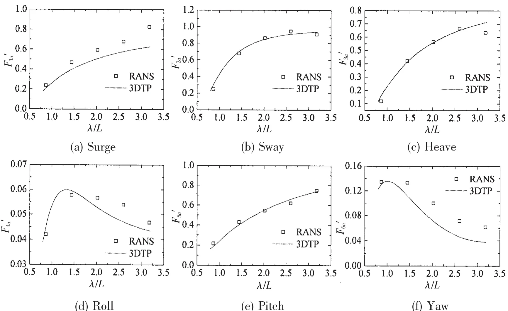
Fig.15 Wave forces in oblique wave(Fn=0.175,β=150°)
4.3 Viscous effect
In the simulation of CFD,both non-linear effect and viscous effect are taken into account.Thus the wave force based on CFD is composed of both frictional force and pressure force.The pressure component can be derived from the total wave force by integrating the pressure on the hull surface,which has been done by utilizing the User Defined Function(UDF).
The comparison of viscous force and pressure force in head wave is shown in Fig.16(Fn=0.175).It is obvious that the viscous component is minimal during all the wave length,which is within expectation.Additionally,we may assume that the pressure components of wave forces based on RANS should equal the wave forces based on potential theory.However,this is not so in practice.The reason may lie in the different theory and numerical method.The pressure component of surge force based on RANS is slightly bigger than that based on potential theory.
The comparison of viscous force and pressure force in oblique wave(Fn=0.175,β=150°)as shown in Fig.17 indicates that the pressure force of surge,heave and pitch is in good agreement with the result based on 3DTP.As for sway force and roll moment,3DTP gives a larger prediction than the pressure component based on RANS in the long wave.The viscous effect accounts for maximum 15%of the total wave forces in surge,sway,heave and yaw and that slight viscous effect could be found in the heave force.As for roll moment,the viscous effect contribute more to the total force,especially in the long wave,peaking at 36.44%at λ=11 m.

Fig.16 The components of wave forces in head wave(Fn=0.175)
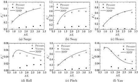
Fig.17 The components of wave forces in oblique wave(Fn=0.175,β=150°)
5 Conclusions
In this study,two numerical methods are utilized to predict the wave excitation force of a ship with transom stern:boundary element method based on 3DTP and CFD method based on an unsteady RANS approach.In the case of CFD,a numerical wave tank is established by using the User Defined Function(UDF)on the commercial code Fluent.In addition,the viscous effect on wave excitation force is studied by taking the advantage of CFD.From this study,the following conclusions can be made:
(1)Compared with the experimental data,both RANS method and 3DTP method give good prediction of wave excitation force,while the RANS method gives slightly better result in the long wave range.
(2)The viscous effect accounts for a large component for the roll moment in oblique wave.
[1]Fang Zhaozhao,Zhu Renchuan,Miao Guoping.Numerical simulation on radiation problems of moving vessels in numerical wave tank[J].Chinese Journal of Hydrodynamics,2011,26(1):65-72.(in Chinese)
[2]Song M J,Kim K H,Kim Y.Numerical analysis and validation of weakly nonlinear ship motions and structural loads on a modern containership[J].Ocean Engineering,2011,38(1):77-87.
[3]Noblesse F and Hendrix D.On the theory of potential flow about a ship advancing in waves[J].Journal of Ship Research,1992,36(1):17-29.
[4]Noblesse F,Huang Fuxin,Yang Chi.Evaluation of ship waves at the free surface and removal of short waves[J].European Journal of Mechanics B/Fluids,2013,38(3):22-37.
[5]Yao C B,Dong W C.A fast integration method for translating-pulsating source Green’s function in Bessho form[J].Journal of Zhejiang University-A,2014,15(2):108-119.
[6]Simonsen C D,Otzen J F,Joncquez S,Stern F.EFD and CFD for KCS heaving and pitching in regular head waves[J].Journal of Marine Science and Technology,2013,18(4):435-459.
[7]Chen X B,Lu D Q.Time-harmonic ship waves with the effect of surface tension and fluid viscosity[C]//Proceedings of the 24th International Workshop on Water Waves and Floating Bodies.Zelenogork,Russia,2009.
[8]Dutykh D.Visco-potential free surface flows and long wave modeling[J].European Journal of Mechanics B/Fluids,2009,28(3):430-443.
[9]Carrica P M,Wilson R V,Stern F.Unsteady RANS simulation of the ship forward speed diffraction problem[J].Computers&Fluids,2006,35(6):545-570.
[10]Wilson R V,Ji L,Karman S L,et al.Simulation of large amplitude ship motions for prediction of fluid-structure interaction[C]//Proceedings of the 27th Symposium on Naval Hydrodynamics.ONR,Seoul,2008.
[11]Fang Zhaozhao,Zhu Renchuan,Miao Guoping,et al.Numerical simulation of diffraction problems of moving vessels in numerical wave tank[J].Journal of Shanghai Jiaotong University,2012,46(8):65-72.(in Chinese)
[12]Guo B J,Steen S,Deng G B.Seakeeping prediction of KVLCC2 in head waves with RANS[J].Applied Ocean Research,2012,35:56-67.
[13]Kim J,Park I,Kim K,et al.Numerical towing tank application to the prediction of added resistance performance of KVLCC2 in regular waves[C].Proceedings of the 2013 International Offshore and Polar Engineering,2013:880-886.
粘性对方尾船波浪力的影响分析
孙小帅,董文才,姚朝帮
(海军工程大学 舰船工程系,武汉 430033)
航行船舶绕射问题的准确求解是预报船舶波浪中运动的基础。文章分别采用基于三维移动脉动源的边界元法和基于RANS方程的CFD方法求解了规则波中航行的方尾船模型的波浪力,并通过与试验结果比较验证了方法的可靠性。CFD计算时通过从波浪力中分离出粘性力,研究了粘性对方尾船波浪力的影响。结果表明,基于RANS方程的波浪力计算结果与试验结果和势流理论结果吻合良好,在长波中与试验值更接近。粘性对船模斜浪航行时的横摇力矩有较
大影响。
波浪力;RANS;粘性;三维移动脉动源格林函数;绕射问题
U661.1
A
国家自然科学基金项目(50879090);水动力重点基金项目(9140A1403071251311044)
孙小帅(1990-),男,海军工程大学舰船工程系博士研究生;
董文才(1967-),男,海军工程大学教授,博士生导师;
姚朝帮(1987-),男,海军工程大学讲师。
U661.1 Document code:A
10.3969/j.issn.1007-7294.2017.12.003
date:2017-07-13
Supported by the National Natural Science Foundation of China(No.50879090)and by the Key Program of Hydrodynamics of China(No.914A14030712JB11044)
Biography:SUN Xiao-shuai(1990-),male,Ph.D.candidate of Naval University of Engineering,E-mail:hglastshadow@163.com;DONG Wen-cai(1967-),male,professor/tutor.
1007-7294(2017)12-1468-12
- 船舶力学的其它文章
- Low-Cycle Fatigue Crack-Propagation Behavior for Ship Cracked Plate Considering Accumulative Plastic Damage
- Numerical Simulation of Deterministic Freak Wave Based on Energy Distribution
- Method of Estimating the Effect of Marine Fouling on Frictional Resistance of Ships
- Numerical Predictions of the PPTC Propeller Tip Vortex Cavitation in Uniform Flow
- Enhanced Extinction Curve Method for Roll Damping Estimation
- Algorithm Simulation of Ship Dynamic Positioning Using Adaptive Fading Memory Filter

