变量齿轮同步分流器的设计及特性仿真
2017-11-24 06:08张旭辉刘平义魏文军田国平李海涛
农业工程学报 2017年14期
张旭辉,刘平义,魏文军,田国平,李海涛※
(1. 中国农业大学工学院,北京 100083;2. 北京颐和中威精密机器有限公司,北京 101113)
变量齿轮同步分流器的设计及特性仿真
张旭辉1,刘平义1,魏文军1,田国平2,李海涛1※
(1. 中国农业大学工学院,北京 100083;2. 北京颐和中威精密机器有限公司,北京 101113)
针对智能农业机械多执行机构同步动作、调速及变载荷恒速运动问题,提出一种变量齿轮同步分流器。分析了中心轮齿数和行星轮均布个数对同步状态的影响,得到各分流单元瞬时状态全部相同的工作条件是中心轮齿数能被行星轮均布个数整除,各分流单元瞬时同步。利用Fluent软件的动网格技术,对分流器流量特性进行非定常模拟,分析出不同中心轮齿数对平均流速和分流器体积的影响。研究了负载压力不变齿轮转速变化、负载压力变化齿轮转速不变、负载压力和齿轮转速均变化的工况下,瞬时流速和平均流速的变化规律。结果表明:行星轮和中心轮回转中心的连线与中心轮参与拟合轮齿的对称中心线重合误差为0.05°和0.1°时,6个出口瞬时流量误差分别为±0.56%和±1.12%;负载压力不变时,根据平均流速与齿轮转速的线性关系,通过伺服电机调节中心轮转速实现变量控制;负载压力变化时,伺服电机调节中心轮转速实现恒流控制,理论上实现了执行机构瞬时同步、调速或恒速动作,试验验证了恒流控制的可行性。
齿轮;同步机械;设计;分流器;仿真分析;流量特性;恒流控制
0 引 言
液压传动因其功率大、安装布置灵活紧凑、调节方便、容易实现无级变速、故障率低等优点,被广泛应用在农业机械上[1-2]。现代化智能农业机械在作业过程中,要求多个执行机构同步动作,如提升部件、作业部件、行走驱动系统等[3-12],液压同步控制的精度尤其高速动作时的同步精度问题是这些系统研究的难点问题。常用的液压同步控制方式[13-14]主要有:节流调速控制、分流集流阀控制、同步分流器控制、比例伺服阀控制等。文献[15-19]对液压同步控制方式的应用进行了研究,文献[20-22]将上述控制方式结合电控技术实现同步,文献[23-24]将上述控制方式进行合理结合实现同步。液压回路中出现的故障大多数是各种阀的故障引起的[25],维修、维护成本高。相对而言,齿轮同步分流器故障率低、性能稳定,且各分流单元尺寸相同,易于实现多路同步控制,文献[26-30]对齿轮同步分流器的同步精度、特性及应用进行了研究。齿轮同步分流器应用在农业机械上,能够实现较高的性价比。
常见的齿轮同步分流器的结构形式是多组啮合齿轮串联在一起,各分流单元一致性受制造和装配精度影响,受串联线路较长时连接轴刚度问题的影响,难以保证各组分流单元齿轮相位的一致性,工作过程中无法实现各分流单元的瞬时流量同步,只能保证单位时间内流量相等,属于平均同步,限制了齿轮式分流器分流精度的提高。一般齿轮式分流器的分流精度为±1.5%~±2.5%[18],在同步精度要求高的系统上的应用受到限制。由于普通的分流器转速是受进出口压力和油液流速控制的,属被动型,负载压力变化时,执行液压缸的动作速度也发生变化,且不能调速。针对上述问题,本文提出一种并联式变量齿轮同步分流器[31],各分流单元的工作状态瞬时同步,理论上无分流误差,能够实现液压系统的精确同步控制,并通过外部驱动调整中心轮的转速,进一步实现执行液压缸变速或恒速同步运动。
1 变量齿轮同步分流器的形成原理及工作条件
变量齿轮同步分流器的原理如图 1所示,由一个中心轮和与其啮合的多个定轴行星轮组成,行星轮均布在中心轮周围,由中心轮啮合驱动定轴线转动,形成多个分流单元。行星轮均布个数为N,则该分流器由N个分流单元组成,分流单元的个数与系统中同步执行件的数目相等。每个分流单元都具有 1个出口和 1个进口,N个进口由一个 1个总进口分流而成,因此该分流器有N个出口和 1个进口。由进口输入的压力油,经由分流块和进口管路分流至各工作单元的入口,因此各入口油压相等。若各工作单元齿轮的轮齿啮合空间的瞬时容积变化相等,则可实现各出口的瞬时流量相等。伺服电机与中心轮联接,通过控制中心轮的转速,实现分流器的变量控制。
顺时针排序为各行星轮命名,使第一个行星轮和中心轮回转中心的连线与中心轮第一个轮齿的对称中心线重合。当在某个行星轮的位置,行星轮和中心轮回转中心的连线再次与某个轮齿的对称中心线重合,则该分流单元的状态与第一个分流单元完全一样,二者瞬时状态同步;若在其余行星轮的位置上都不会出现二线重合的情况,则每个分流单元的瞬时状态都不同步,但平均同步。如图2所示,第1分流单元与第3分流单元出现二线重合,但此刻与第2分流单元未出现二线重合。
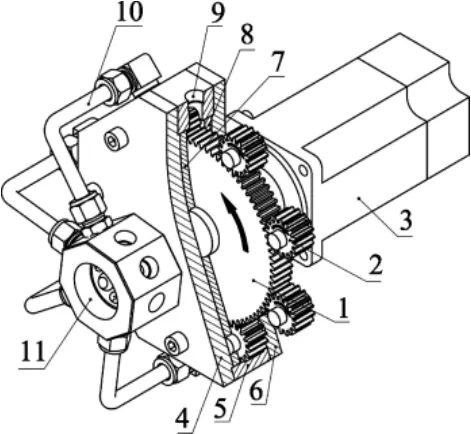
图1 变量齿轮同步分流器结构示意图Fig.1 Structure diagram of variable gear synchronous shunt
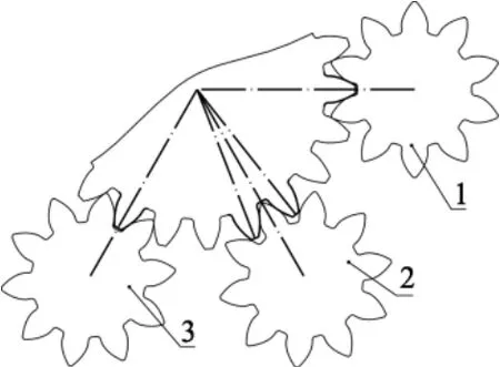
图2 分流单元的轮齿啮合Fig.2 Meshing of teeth of shunt units
令中心轮齿数为z1,正整数k为z1与N的最大公约数,分为以下3种情况:
1)k=N,即z1能被N整除,N个分流单元的瞬时状态全部相同,各分流单元瞬时同步。
2)1<k<N,即z1不能被N整除,但z1和N能同时被k整除,N个分流单元的瞬时状态分组相同,组数为N/k,每组k个分流单元瞬时同步,各组之间平均同步。
3)k=1,N个分流单元的瞬时状态全部不同。N个分流单元平均同步。
根据以上分析,N个行星轮均布,z1能被N整除时,各分流单元瞬时同步,为变量齿轮同步分流器工作条件;z1和N的最大公约数为1时,行星轮每转排量相同,实现平均同步,与现有串联齿轮同步分流器相同。
2 变量齿轮同步分流器各出口瞬时流量
2.1 啮合点位置分析
中心轮和某个行星轮啮合如图3所示。A点为一对轮齿的起始啮合点;B点为这对轮齿的终止啮合点;C点为中心轮和行星轮啮合的节点,该点是一个定点;D点为下一对轮齿进入啮合点A时,当前轮齿的啮合点;M为排油轮齿瞬时啮合点;fi为瞬时啮合点M至节点C的距离。
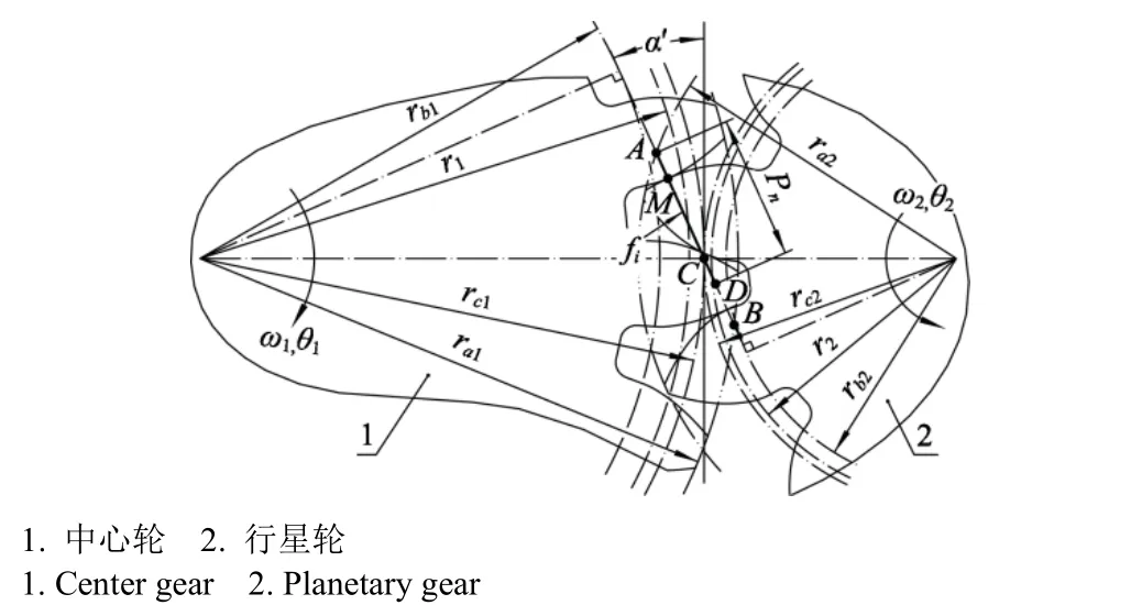
图3 中心轮与行星轮啮合示意图Fig.3 Meshing diagram of center gear and planetary gear
z1能被N整除时,各分流单元瞬时排油啮合点的位置关系为

式中f1、f2、…fi、…fN分别为第 1、2、…i、…N个分流单元的齿轮啮合点M距节点C的距离,m。因上述各变量的值瞬时相同,规定f为统一变量。
f的取值如下表述:以节点C为零点,规定C点以左(AC方向)为负值,C点以右(CD方向)为正值,则f(m)取值范围为

式中m为齿轮的模数,m;α为渐开线齿轮的压力角,rad。
2.2 各出口的理论流量方程
z1能被N整除时,分流器各出口的瞬时流量、相位完全相同。根据有限体积法(finite volume method)[32],得到各出口的理论瞬时流量Qins(m3/s)的方程
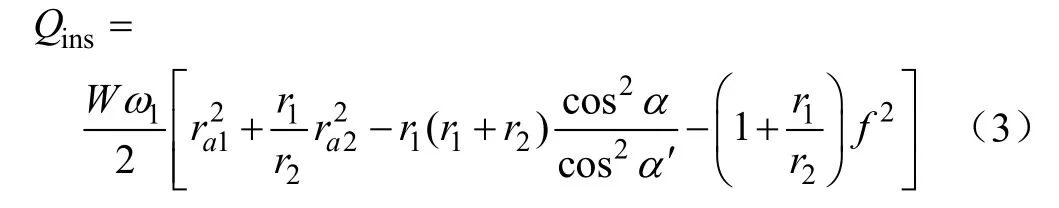
式中W为中心轮和行星轮的轴向宽度,m。
每个分流单元的行星轮旋转一周所排出的流体体积为一对轮齿在其啮合周期中所排出的流体体积与行星轮齿数z2之积[33],根据这个原理可知,在不考虑泄漏、压力等因素的情况下,各分流单元的出口排量V(m3/r)相等。
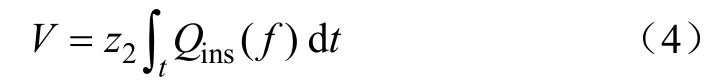
式中t是一对轮齿啮合周期中的有效排油时间,即图3啮合点从A点出发运动到D点所用的时间,s。
根据渐开线的特性,有
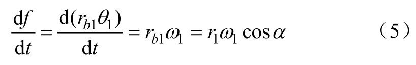
将式(3)和(5)代入式(4),得到分流单元出口理论排量方程
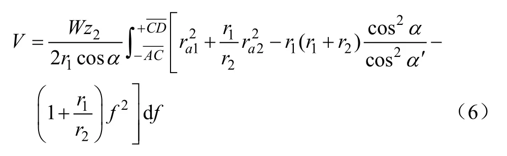
则理论流量qth(m3/min)为
式中n2为行星轮转速,r/min。
因分流器出口尺寸确定,瞬时流量qins(m3/min)和瞬时流速vins(m/s)之间、平均流量qme(m3/min)和平均流速vme(m/s)之间存在以下关系
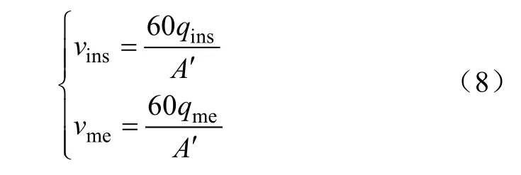
式中A′为分流单元出口截面面积,m2。
因此,可用瞬时流速体现出口瞬时流量的特征,用平均流速体现出口的平均流量特征。
由上述公式可知,变量齿轮同步分流器各分流单元的瞬时流量或瞬时流速相等,因此各分流单元的瞬时工作状态完全相同,各分流单元瞬时同步。平均流量或平均流速相等条件自然满足。
3 变量齿轮同步分流器关键设计参数确定
同步分流器关键设计参数的确定过程如下:初步建立几何模型——仿真试验——分析——确定参数。
3.1 算例几何模型的建立
设定系统中同步执行件的数目为6,则行星轮的均布个数N=6,参考力士乐外啮合齿轮泵 PF-008(排量为8 mL/r)的齿轮,选取中心轮和行星轮的模数m=3,行星轮齿数均为z2=10,变位系数x2=0.5。中心轮参与进油腔和排油腔隔离的齿数至少为1,再根据各分流单元的同步条件,计算出中心轮齿数z1为 36、42、48、54、60、72、…。将不同中心轮齿数作为不同算例进行几何建模,中心轮齿数对应的参与隔离齿数如表 1所示。分流器各进口尺寸均为14 mm,各出口尺寸均为12 mm,中心轮和行星轮齿顶圆与壳体的径向间隙均为0.1 mm。为方便比较,建模时将各算例的分流单元齿轮设置在同一个相位。
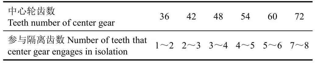
表1 分流器中心轮参与隔离的齿数Table 1 Teeth number that center gear engages in isolation in shunt
3.2 仿真试验
运用ANSYS软件中的ICEM CFD、Fluent和CFDPost 3个模块对不同中心轮齿数模型进行流量特性仿真试验。
3.2.1 仿真试验准备及数据后处理方法
1)计算模型的建立
将各算例建立的几何模型导入ICEM CFD模块。以算例z1=48为例,其流体域如图4所示,各算例的流体域与该算例类似。
对各算例的流体域进行网格划分,全局采用三角形非结构网格;将生成的流体域网格文件导入Fluent模块,用动网格技术进行流场非定常数值模拟,因流体在分流器中的流动状态为湍流,设置模型为非稳态流动、k-ε湍流模型,压力-速度耦合方式选用 PISO,油液选用L-HM46,密度ρ=866 kg/m3,黏度为 0.041 4 Pa·s;设置分流器的6个入口的表压均为4.5 MPa;运用UDF宏[34]定义中心轮和行星轮转速,行星轮与中心轮的转速比等于中心轮与行星轮的齿数比,不同中心轮齿数模型中行星轮的转速均为209.44 rad/s(即2 000 r/min),中心轮的转速设置如表 2所示。设置时间步为 1e-5 s,每 25步保存一次(0.25 ms),即每25步完成一次数据采样。
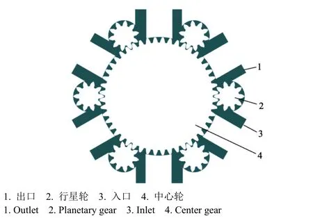
图4 分流器仿真模型的计算流体域Fig.4 Computing flow domain of shunt simulation model
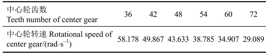
表2 不同中心轮齿数模型的中心轮转速设置Table 2 Center gear rotational speed setting of different models which have different center gear teeth number
2)计算数据后处理
将Fluent模块计算生成的数据文件导入CFD-Post模块进行数据后处理。在 6个出口端口中心建立监测点,得到瞬时流速随时间的变化规律。
3.2.2 仿真试验结果
将以上各算例计算模型的出口压力均设为4 MPa。由于所建立几何模型存在必要的径向间隙,分流器工作时将产生径向泄漏,将影响出口流量。各算例的出口(图4所示出口)瞬时流速曲线、中心轮齿数与出口平均流速的关系曲线及与中心轮齿顶圆关系曲线如图5所示。
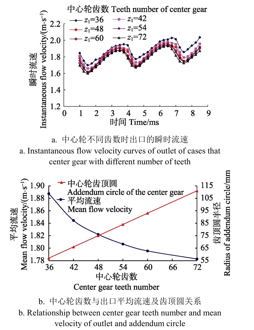
图5 中心轮不同齿数时出口的仿真曲线Fig.5 Simulation curves of outlet of cases that center gear with different number of teeth
由图 5可以看出,随着中心轮齿数的增多,平均流速减小,但减小幅度逐渐变缓。由于油液泄漏方向为进油腔到出油腔,根据式(8)流速与流量的关系,平均流速的减小,意味着泄漏量减少,进而分流精度提高,但中心轮的直径却线性增大,使得分流器的体积增大。中心轮齿数为图5b中两条曲线交点附近的z1=48时,能够兼顾分流精度和分流器体积,选取中心轮齿数为48的分流器作为研究对象,进行模拟仿真分析。此时,中心轮参与隔离的齿数为3~4。
4 变量齿轮同步分流器的流量特性仿真分析
在 Fluent模块中,保持流场模型参数等设置不变,入口压力为4.5 MPa,各出口压力相同,对N=6、m=3、z1=48、z2=10的分流器模型分别在负载压力变化、负载压力不变时改变行星轮转速实现变量、负载压力变化时调节行星轮转速实现恒流等工况下进行流体特征仿真分析。出口压力小于进口压力时,分流器处于马达工作状态,出口压力大于进口压力时,分流器处于类泵工作状态,出口压力等于进口压力时为临界状态。
4.1 分流器各出口压力相同时工况分析
设置6个出口的压力均为4 MPa,行星轮的转速为2 000 r/min。各出口的瞬时流速情况如图6所示。
由图6可以看出,6个出口的瞬时流速曲线重合。说明6个分流单元的瞬时工作状态相同,各分流单元瞬时同步。
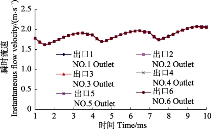
图6 出口压力为4 MPa时6个出口的瞬时流速Fig.6 Instantaneous flow velocity curves of 6 outlets whose pressure values are all 4 MPa
考虑到加工、安装等误差,综合影响图 2所示二线重合的精度,最终表现在各分流单元瞬时流速曲线之间的相位出现偏差,进而影响到瞬时分流精度。对于z1=48的模型,依据仿真分析每隔0.25 ms采样的数据,将任一出口数据曲线沿时间轴位移,与位移前数据进行比较,每一采样时间上两条曲线上数据的最大差值即为二线重合存在误差时的瞬时分流误差。结合CAD软件,绘制齿轮啮合图,测量出二线重合无误差和存在误差两种状态下啮合点的位置误差δ(m),则相位误差为
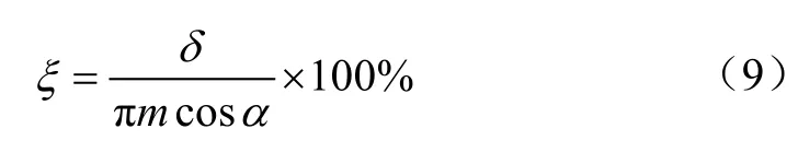
二线重合误差为0.05°时,相位误差为0.73%,瞬时分流误差为±0.56%;二线重合误差为 0.1°时,相位误差为1.46%,瞬时分流误差为±1.12%。
4.2 负载压力不同时的工况分析
保持分流器各齿轮的转速为2 000 r/min,将分流器6个出口压力设置为相同值,分别为4、4.25、4.5、4.75和5 MPa。其中出口压力为4和4.25 MPa时分流器处于马达工作状态,出口压力为4.75和5 MPa时处于类泵工作状态,出口压力为4.5 MPa时处于临界工作状态。因各分流单元的状态瞬时同步,可任选一出口收集数据。选取出口1,得到的瞬时流速和平均流速曲线如图7所示。
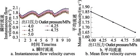
图7 分流器不同负载压力下出口1的瞬时流速和平均流速Fig.7 Instantaneous flow and mean flow velocity curves of outlet 1 under different load pressures
由图 7可以看出,随着出口压力不同,出口瞬时流速曲线按照压力增长递减,各出口平均流速随着出口压力的升高,线性下降,不受分流器工作状态的影响。
4.3 负载压力不变,分流器变量工况分析
分流器出口流量的变化通过伺服电机驱动中心轮,改变各齿轮的转速实现。分别设置行星轮转速n2为1 000、1 250、1 500、1 750和2 000 r/min,出口压力均设置为4 MPa,对各转速工况进行仿真分析,任选一出口收集数据。选取出口1,得到的瞬时流速和平均流速曲线如图8所示。
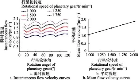
图8 不同行星轮转速工况下出口1的瞬时流速和平均流速Fig.8 Instantaneous flow and mean flow velocity curves of outlet 1 under conditions that rotational speed of planetary gear is different
由图 8可以看出,随着转速的增加,平均流速线性增长。因此,在负载压力不发生变化的情况下,要实现各出口流速的改变,可通过控制伺服电机的转速线性变化来实现。
4.4 负载压力变化时,分流器恒流控制
分流器工作过程中,负载压力变化时,进出口压差发生变化,将导致流速的变化,会使得执行液压缸的速度发生变化。
分别仿真不同转速下不同负载压力的工况,选取出口1,得到各工况下的平均流速如表3所示。
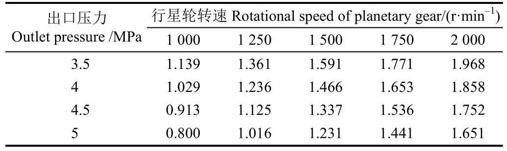
表3 不同转速和负载压力工况的出口平均流速Table 3 Mean flow velocity values of outlet under different rotational speed and load pressure values (m·s–1)
以表 3为依据,当负载压力变化时,可通过伺服电机调节中心轮和行星轮的转速,使各分流单元出口平均流速不变,实现恒流工作状态,达到执行液压缸匀速运动的要求。
5 流体特性试验
因分流单元的数目与系统中同步执行件的数目相等,满足瞬时同步条件的分流单元数目与分流器流体特性无关。试制了具有代表性的 3个分流单元的变量齿轮同步分流器试验样机,单个分流单元的排量为 8 mL/r,在泵与马达专用试验台(北京海昊天威机电技术有限公司自制)上构建的分流器试验系统如图 9所示。该试验台可测量泵和马达出口的压力和平均流量,压力表显示负载压力,数字流量计显示平均流量。设定不同的负载压力,通过伺服电机调整分流器中心轮的转速,使各出口的平均流量稳定于设定值。记录出口 1在不同压力下实现给定平均流量时的行星轮转速数据,如表4所示。
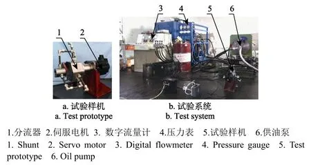
图9 分流器试验系统Fig.9 Shunt test system
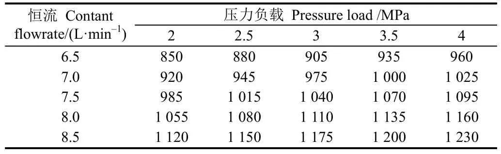
表4 负载变化时不同恒流状态的行星轮转速Table 4 Rotational speed of planetary gear under different contant flow rate states when load changes (r·min–1)
从表 4可以看出,负载压力变化时,利用伺服电机调节分流器齿轮的转速,实现了恒流控制,各分流单元的恒流控制特性相同。
针对表3,运用插值法求得行星轮转速为1 200 r/min、负载压力为3.5 MPa时的平均流速为1.317 m/s。对比表3和 4中负载压力为3.5 MPa、行星转速为1 000 r/min和1 200 r/min时的平均流速和平均流量,根据式(8)分别计算分流单元出口截面面积A′,得到分流单元出口截面积误差为4.6%,进而得到A′不变时的平均流量误差为4.6%,验证了仿真分析结果的正确性。
6 结 论
1)变量齿轮同步分流器的工作条件是N个行星轮均布,中心轮齿数z1能被行星轮分布个数N整除。经仿真验证,分流器各出口的瞬时流速曲线重合,N个分流单元瞬时状态全部相同,各分流单元瞬时同步。理论上实现了多路液压系统瞬时同步,可应用于高精度同步控制系统中。
2)随着中心轮参与隔离进油腔和排油腔齿数的增多,平均流速减小,减小幅度逐渐变缓,泄漏量减少,但分流器的体积增大。行星轮均布个数为 6,齿数为 10时,选取中心轮的最佳齿数为48。
3)负载压力不变,行星轮和中心轮回转中心的连线与中心轮参与拟合轮齿的对称中心线重合误差为0.05°和0.1°时,瞬时分流误差分别为±0.56%和±1.12%。平均流速随着齿轮转速增加线性增大,由伺服电机调整中心轮转速,变量齿轮同步分流器实现变量同步,末端执行机构同步变速运动。
4)负载压力变化时,平均流速随着负载压力的升高线性下降,由伺服电机提升中心轮转速,变量齿轮同步分流器实现恒流同步,末端执行机构同步匀速运动,为变量齿轮同步分流器在智能农业机械上的应用提供理论基础,可进一步将该分流器应用于终端执行机械装置上进行同步性能测试研究。
[1] 曹玉宝. 液压技术在现代农业机械中的应用现状与趋势[J]. 农机化研究,2008(5):194-196.Cao Yubao. Application status and trends of hydraulic technologies in agricultural machinery[J]. Journal of Agricultural Mechanization Research, 2008(5): 194-196. (in Chinese with English abstract)
[2] Huyghebaert B, Lorencowicz E, Uziak J. Repair cost of tractors and agricultural machines in family farms[J]. Agriculture &Agricultural Science Procedia, 2015, 7: 152-157.
[3] 李明生,朱忠祥,毛恩荣,等. 大功率拖拉机电液提升器比例提升阀设计[J]. 农业机械学报,2012,43(10):31-35.Li Mingsheng, Zhu Zhongxiang, Mao Enrong, et al. Design of proportional raise valve in electro-hydraulic lifting mechanism of big-power tractor[J]. Transactions of the Chinese Society for Agricultural Machinery, 2012, 43(10): 31-35. (in Chinese with English abstract)
[4] 赵建军,朱忠祥,宋正河,等. 重型拖拉机电液提升器多路换向阀仿真与试验[J]. 农业机械学报,2014(增刊1):1-9.Zhao Jianjun, Zhu Zhongxiang, Song Zhenghe, et al. Simulation and experiment on multi-directional valve of heavy tractor electro-hydraulic hitch[J]. Transactions of the Chinese Society for Agricultural Machinery, 2014(Supp.1): 1-9. (in Chinese with English abstract)
[5] 杨华勇,曹剑,徐兵,等. 多路换向阀的发展历程与研究展望[J]. 机械工程学报,2005,41(10):1-5.Yang Huayong, Cao Jian, Xu Bing, et al. Progress in the evolution of directional control valves and future trends[J].Chinese Journal of Mechanical Engineering, 2005, 41(10):1-5. (in Chinese with English abstract)
[6] 张志起,崔中凯,刘继元,等. 4YX-4型全液压自走式玉米收获机液压系统设计[J]. 农机化研究,2015(12):97-101.Zhang Zhiqi, Cui Zhongkai, Liu Jiyuan, et al. Hydraulic system design of 4YX-4 type full-hydraulic self-propelled corn harvester[J]. Journal of Agricultural Mechanization Research,2015(12): 97-101. (in Chinese with English abstract)
[7] 梁荣庆,坎杂,李成松,等. 液压传动技术在收获机械中的应用研究[J]. 机床与液压,2012,40(20):152-156.Liang Rongqing, Kan Za, Li Chengsong, et al. Applied research of hydraulic drive technology in harvest machinery[J].Machine Tool & Hydraulics, 2012, 40(20): 152-156. (in Chinese with English abstract)
[8] 吕小荣,丁为民,吕小莲. 丘陵山区小型多功能底盘液压系统的设计[J]. 华中农业大学学报,2014,33(2):128-132.Lv Xiaorong, Ding Weiming, Lv Xiaolian. Design of hydraulic system of small multi-function chassis in hilly area[J]. Journal of Huazhong Agricultural University, 2014,33(2): 128-132. (in Chinese with English abstract)
[9] 金鑫,杜新武,杨传华,等. 蔬菜移栽穴盘苗自动输送装置设计与试验[J]. 农业机械学报,2016,47(7):103-111.Jin Xin, Du Xinwu, Yang Chuanhua, et al. Design and experiment on automatic transporting mechanism for vegetable potted seedlings[J]. Transactions of the Chinese Society for Agricultural Engineering, 2016, 47(7): 103-111.(in Chinese with English abstract)
[10] 董东双,邓洪超,马文星. 多功能清雪车单泵多马达液压系统功率分配分析[J]. 农业工程学报,2010,26(7):140-146.Dong Dongshuang, Deng Hongchao, Ma Wenxing. Power allocation analysis of hydraulic system with single pump and multiple motors of multifunctional snow-plough[J]. Transactions of the Chinese Society of Agricultural Engineering (Transactions of the CSAE), 2010, 26(7): 140-146. (in Chinese with English abstract)
[11] 高国琴,王威,丁琴琴. 农业并联机器人同步滑模控制[J].农业机械学报,2012,43(9):173-178,196.Gao Guoqin, Wang Wei, Ding Qinqin. Synchronization sliding mode control for agricultural parallel robot[J]. Transactions of the Chinese Society for Agricultural Machinery, 2012,43(9): 173-178, 196. (in Chinese with English abstract)
[12] 王占海,王伟,金金. 液压控制技术在蒲草收割船割台上的应用与研究[J]. 液压与气动,2014(4):73-75,79.Wang Zhanhai, Wang Wei, Jin Jin. The research and application on hydraulic control technology for cutting platform of cattail harvesting ship[J]. Chinese Hydraulics & Pneumatics,2014(4): 73-75,79. (in Chinese with English abstract)
[13] 李萌,张龙江. 中包车液压同步回路比较[J]. 液压与气动,2013(11):7-10.Li Meng, Zhang Longjiang. Comparison of hydraulic synchronous circuit for tundish car[J]. Chinese Hydraulics & Pneumatics,2013(11): 7-10. (in Chinese with English abstract)
[14] 杨文彬. 多液压缸同步系统的设计及其控制策略研究[D].长沙:中南大学,2014.Yang Wenbin. The Design and Control Strategy Research of Multi-cylinder Synchronous System[D]. Changsha: Central South University, 2014. (in Chinese with English abstract)
[15] 许立,庞海军,施志辉,等. 基于AMESim的液压同步阀集流工况仿真与分析[J]. 机械科学与技术,2012,31(9):1535-1538.Xu Li, Pang Haijun, Shi Zhihui, et al. Simulating and analyzing conflux conditions of hydraulic synchronization valve with AMESim[J]. Mechanical Science and Technology for Aerospace Engineering, 2012, 31(9): 1535-1538. (in Chinese with English abstract)
[16] Abbas R, Al-baldawi Y, Abullah F. Theoretical and experimental study of hydraulic actuators synchronization by using flow divider valve[J]. Journal of Engineering and Development, 2014, 18(5): 283-293.
[17] 贾剑峰. 分流集流阀在全液压平地机中的应用研究[D].西安:长安大学,2009.Jia Jianfeng. Application and Research of Dividing- Combining Valve on the Full Hydraulic Grader[D]. Xi’an: Chang’an University, 2009. (in Chinese with English abstract)
[18] 陈德国,李慧忠,柏峰,等. 多流液压同步马达应用研究[J]. 机床与液压,2010,38(8):55-56.Cheng Deguo, Li Huizhong, Bai Feng, et al. Research on multi-flow hydraulic synchronous motor[J]. Machine Tool &Hydraulics, 2010, 38(8): 55-56. (in Chinese with English abstract)
[19] 魏列江,王霖,冯志清,等. 突变负载下基于同步马达的液压同步举升系统研究[J]. 液压与气动,2014(3):71-75.Wei Liejiang, Wang Lin, Feng Zhiqing, et al. Research on hydraulic synchronous lifting system based on synchronous motor under the mutation load[J]. Chinese Hydraulics &Pneumatics, 2014(3): 71-75. (in Chinese with English abstract)
[20] Wines T, Burton R, Schoenau G, et al. Optimization and experimental verification of a variable ration flow diver valve[J]. International Journal of Fluid Power, 2005, 6(3):45-53.
[21] Chen C Y, Liu L Q, Cheng C C, et al. Fuzzy controller design for synchronous motion in a dual-cylinder electrohydraulic system[J]. Control Engineering Practice, 2008,16(6): 658-673.
[22] 梁宗辉,冉文浩,薛华,等. 双动滑阀同步电液控制系统设计[J]. 液压与气动,2005(7):75-76.Liang Zonghui, Ran Wenhao, Xue Hua, et al. Design of a synchronized electro-hydraulic control system for double acting slide valve[J]. Chinese Hydraulics & Pneumatics,2005(7): 75-76. (in Chinese with English abstract)
[23] 王才东,王立权,赵冬岩. 多马达液压同步控制系统设计及试验研究[J]. 机床与液压,2013,41(11):5-9.Wang Caidong, Wang Liquan, Zhao Dongyan. Design and experimental study of multi-motors hydraulic synchronization control system[J]. Machine Tool and Hydraulics, 2013,41(11): 5-9. (in Chinese with English abstract)
[24] 杨文彬,胡军科,王子坡. 两级双向液压同步控制系统动态特性仿真[J]. 浙江大学学报:工学版,2014,48(6):1107-1113.Yang Wenbin, Hu Junke, Wang Zipo. Dynamic characteristics simulation of two-stage bi-direction hydraulic synchronization control system[J]. Journal of Zhejiang University: Engineering Science, 2014, 48(6): 1107-1113. (in Chinese with English abstract)
[25] 湛从昌. 液压可靠性与故障诊断[M]. 北京:冶金工业出版社,2009.
[26] 文明,周黎,赵明岗,等. 液压分流马达特性分析与应用研究[J]. 液压气动与密封,2013(1):37-40.Wen Ming, Zhou Li, Zhao Minggang, et al. Characteristic analysis and applied research of the hydraulic synchronous motor[J]. Hydraulics Pneumatics & Seals, 2013(1): 37-40.(in Chinese with English abstract)
[27] 杨立勤,温济全. 齿轮式液压分流器同步精度的理论分析[J]. 液压气动与密封,1996(3):7-9.Yang Liqin, Wen Jiquan. Theoretical analysis of gear type hydraulic diverter synchronous precision[J]. Hydraulics Pneumatics &Seals, 1996(3): 7-9. (in Chinese with English abstract)
[28] 孙飞,熊瑞平,党磊,等. 基于AMESim的齿轮分流马达的同步误差分析[J]. 液压与气动,2016(12):65-69.Sun Fei, Xiong Ruiping, Dang Lei, et al. The synchronization error analysis of gear shunt motor based on AMESim[J].Chinese Hydraulics & Pneumatics, 2016(12): 65-69. (in Chinese with English abstract)
[29] 郭廷善. 精密制品双向压制液压系统原理设计应用[J]. 液压气动与密封,2013(2):85-86.Guo Tingshan. Precision products two-way suppress hydraulic principle design applications[J]. Hydraulics Pneumatics & Seals,2013(2): 85-86. (in Chinese with English abstract)
[30] 陈艳伟. 齿轮同步器流场分析与同步特性研究[D]. 秦皇岛:燕山大学,2011.Chen Yanwei. Gear Synchronizer Flow Field Analysis and Synchronicity Research[D]. Qinhuangdao: Yanshan University,2011. (in Chinese with English abstract)
[31] 魏文军,张旭辉,李海涛,等. 一种变量齿轮同步分流器:CN201510354507.1[P]. 2015-09-09.
[32] Huang K J,Lian W C. Kinematic flowrate characteristics of external spur gear pumps using an exact closed solution [J].Mechanism and Machine Theory, 2009, 44(6): 1121-1131.
[33] 李壮云.液压元件与系统[M]. 北京:机械工业出版社,2014.
[34] 胡坤,李振北. ANSYS ICEM CFD工程实例详解[M]. 北京:人民邮电出版社,2014.
Design and characteristic simulation of variable gear synchronous shunt
Zhang Xuhui1, Liu Pingyi1, Wei Wenjun1, Tian Guoping2, Li Haitao1※
(1.College of Engineering, China Agricultural University, Beijing100083,China;2.Beijing Yihezhongwei Precision Machine Co.,Ltd., Beijing101113,China)
Modern intelligent agricultural machinery in the course of operation requires multiple actuators synchronous action.Commonly used hydraulic synchronous control methods are throttling speed control, dividing-collecting valve control,synchronous shunt control, and proportional servo valve control. In contrast, gear synchronous shunt has a low fault rate, stable performance, and the same size of the shunting units. It is easy to achieve multi-loop synchronous control. The structure of general gear shunt is tandem, which is difficult to guarantee the consistency of the gear phases in shunting units. The instantaneous flow rates of every shunting unit cannot be synchronized in the working process. When the load pressure is changed, the action speed of the hydraulic cylinder is changed using such a tandem gear shunt in hydraulic circuit, and the speed cannot be adjusted. Aiming at the problems mentioned above, a parallel variable gear synchronous shunt was proposed in this paper. The influence of center gear teeth number and uniformly distributed planetary gear numbers on synchronization status of the shunting units was analyzed. The working condition was the center gear teeth number that can be divided by uniformly distributed planetary gears number, from which shunting unit instantaneous states were all the same. By analyzing the gear meshing point position of a shunting unit, the instantaneous flow and theoretical displacement formulas of shunt outlet were deduced. The outlet instantaneous flow rate can be characterized by instantaneous flow velocity, and the outlet mean flow rate can be characterized by mean flow velocity. The instantaneous flow rate or instantaneous flow velocity of shunting units contained in the variable gear synchronous shunt were equal. Therefore, the instantaneous working statuses of every shunting unit were exactly the same, and the shunting units were instantaneously synchronized. Then the mean flow rate or the mean flow velocity equal conditions were naturally satisfied. The geometric models of different cases were created, and then the meshes of flow domains were divided properly using triangular unstructured meshes globally in the ICEM CFD module.Finally, the generated mesh files were imported into the Fluent module for simulation analysis. After the flow domain model parameters were set in the Fluent module, the transient flow characteristics of the shunt were simulated by using the dynamic mesh technique. The data files generated by Fluent module calculation were imported into the CFD-Post module for data post-processing. By setting up monitoring points at the center of outlets, variation law of flow velocity with time was gained.After analyzing influence of different center gear teeth number on the mean flow velocity and the shunt geometrical dimensions, an appropriate center gear teeth number was selected under the limits of shunt accuracy and shunt size. In order to get variation law of instantaneous flow velocity and main flow velocity, the shunt was studied in the following conditions:constant load pressure with a changing gear speed, a changing pressure with constant gear speed, and a concurrently changing load pressure and gear speed. The results showed that, when the coincidence errors of the two lines were 0.05° and 0.1°, the instantaneous shunt errors were ±0.56% and ±1.12%. When the load pressure was constant, variable control can be realized by adjusting the center gear rotational speed through a servo motor. When the load pressure was changed, constant flow control can be achieved by adjusting the center gear rotational speed also. A three-gear shunt test prototype was developed. In order to complete the constant flow control test, the test prototype was connected to the pump and motor dedicated test bench to build a test system. The experimental results of constant flow rate control verified the correctness and feasibility of simulation results.In this study, instantaneous synchronization, speed regulation or constant speed motion of the actuators can be realized theoretically, which provides a theoretical basis for the high precision synchronous control of the variable gear synchronous shunt on the intelligent agricultural machinery.
gears; synchronous machinery; design; shunt; simulation analysis; flow characteristics; constant flow control
10.11975/j.issn.1002-6819.2017.14.009
TH137.8+4
A
1002-6819(2017)-14-0063-07
张旭辉,刘平义,魏文军,田国平,李海涛. 变量齿轮同步分流器的设计及特性仿真[J]. 农业工程学报,2017,33(14):63-69.
10.11975/j.issn.1002-6819.2017.14.009 http://www.tcsae.org
Zhang Xuhui, Liu Pingyi, Wei Wenjun, Tian Guoping, Li Haitao. Design and characteristic simulation of variable gear synchronous shunt[J]. Transactions of the Chinese Society of Agricultural Engineering (Transactions of the CSAE), 2017, 33(14):63-69. (in Chinese with English abstract) doi:10.11975/j.issn.1002-6819.2017.14.009 http://www.tcsae.org
2016-11-06
2017-05-22
国家自然科学基金资助项目(51405494)
张旭辉,男,河北张家口人,博士生,主要从事农用底盘研究。北京 中国农业大学工学院,100083。Email:zhangxuhui0103@163.com
※通信作者:李海涛,男,湖北襄阳人,副教授、博士生导师,博士,主要从事机械设计及理论研究。北京 中国农业大学工学院,100083。
Email:h.li@cau.edu.cn
猜你喜欢
江西通信科技(2022年3期)2022-10-11
预防青少年犯罪研究(2022年1期)2022-08-15
中国重型装备(2022年2期)2022-04-19
百科探秘·航空航天(2020年6期)2020-07-09
电子技术与软件工程(2019年21期)2020-01-16
中国特种设备安全(2019年8期)2019-10-14
中学生数理化·八年级物理人教版(2019年5期)2019-06-25
读者(2018年20期)2018-09-27
制造技术与机床(2017年12期)2017-02-02
少儿科学周刊·儿童版(2016年1期)2016-03-14