
Review on signal-by-wire and power-by-wire actuation for more electric aircraft
2017-11-20 01:55JenChrlesMAREJinFU
CHINESE JOURNAL OF AERONAUTICS 2017年3期
Jen-Chrles MARE´,Jin FU,b,*
aInstitut National des Sciences Appliquees,Institut Clement Ader(CNRS UMR 5312),Toulouse 31077,France
bSchool of Mechanical Engineering and Automation,Beihang University,Beijing 100083,China
Review on signal-by-wire and power-by-wire actuation for more electric aircraft
Jean-Charles MARE´a,Jian FUa,b,*
aInstitut National des Sciences Appliquees,Institut Clement Ader(CNRS UMR 5312),Toulouse 31077,France
bSchool of Mechanical Engineering and Automation,Beihang University,Beijing 100083,China
Available online 20 April 2017
*Corresponding author at:School of Mechanical Engineering and Automation,Beihang University,Beijing 100083,China.
E-mail address:fujianbuaa@126.com(J.FU).
Peer review under responsibility of Editorial Committee of CJA.
Production and hosting by Elsevier
http://dx.doi.org/10.1016/j.cja.2017.03.013
1000-9361©2017 Chinese Society of Aeronautics and Astronautics.Production and hosting by Elsevier Ltd.
This is an open access article under the CC BY-NC-ND license(http://creativecommons.org/licenses/by-nc-nd/4.0/).
The huge and rapid progress in electric drives offers new opportunities to improve the performances of aircraft at all levels:fuel burn,environmental footprint,safety,integration and production,serviceability,and maintainability.Actuation for safety-critical applications like flight-controls,landing gears,and even engines is one of the major consumers of non-propulsive power.Conventional actuation with centralized hydraulic power generation and distribution and control of power by throttling has been well established for decades,but offers a limited potential of evolution.In this context,electric drives become more and more attractive to remove the natural drawbacks of conventional actuation and to offer new opportunities for improving performance.This paper takes the stock,at both the signal and power levels,of the evolution of actuation for safety-critical applications in aerospace.It focuses on the recent advances and the remaining challenges to be taken toward full electrical actuation for commercial and military aircraft,helicopters,and launchers.It logically starts by emphasizing the specificity of safety-critical actuation for aerospace.The following section addresses in details the evolution of aerospace actuation from mechanically-signaled and hydraulically-supplied to all electric,with special emphasis on research and development programs and on solutions entered into service.Finally,the last section reviews the challenges to be taken to generalize the use of all-electric actuators for future aircraft programs.
©2017 Chinese Society of Aeronautics and Astronautics.Production and hosting by Elsevier Ltd.This is an open access article under the CC BY-NC-ND license(http://creativecommons.org/licenses/by-nc-nd/4.0/).
Actuator;
Aerospace;
Electrohydrostatic;
Electromechanical;
Hydraulic;
More electric aircraft;
Power-by-wire;
Signal-by-wire
1.Introduction
In recent years,aerospace actuation has made significant steps forward thanks to extensive introduction of the electrical technology at both signal and power levels.Despite scientific progresses and the industrial pressure to make aircraft safer,cheaper,and greener and to reduce time to market,efforts toward more electric then all electric aircraft are not always visible when one concentrates only on the solutions brought into service.This review intends to highlight recent advances and remaining challenges to be taken for enabling power-bywire(PbW)to be extensively used for actuation in aerospace.
Following the systems engineering approach,any product development should follow a ‘top-down” approach starting first from the elicitation of needs and their transformation into requirements to define a proposed solution.In practice,this process is often reversed as a ‘bottom-up”process that consists of starting from(almost)mature technology for combining components to make equipment,subsystems,and then systems that offer new services to a customer.The first approach enables disruptive innovation but may ignore state-of-the-art technology and consequently may fail in putting a mature product into mass production.The second approach limits risks but only generates incremental innovation which brings low benefits when the employed technology has been well established for decades.However,this approach can take advantage of local step changes.A good example is found for hydraulic servo actuators(HSAs)that can be significantly improved by using new materials(e.g.,carbon fiber reinforced housings1)and new manufacturing processes(e.g.,additive manufacturing)2–4or by making them smart through integration of electronic boards and interfaces with digital networks.An intermediate or ‘middle-out” approach is efficient to solve this dilemma.It consists of combining these two approaches to inject a realistic view of technological maturity(bottom-up)for filtering and making decision at each step of the top-down process.5Introduced by the NASA for space programs,the technology readiness levels(TRL)scale6provides an efficient way to measure at a given date the remaining activities for putting a product into operational service.At TRL2,a concept is formulated.At TRL4,it is validated by testing a demonstrator in a soft laboratory environment.At TRL9,it is put into service.Reviewing the evolution of actuation for aerospace highlights the major importance taken by the technological maturity that comes essentially from the time scale of aircraft life,from project launch to service withdrawal.Electro-hydrostatic actuators(EHAs)give a striking example of this time scale:it took about 15 years to move from TRL4( first ground tests in the early 1990s)to TRL9(entry into service,EIS,on Airbus A380 in 2007).An aircraft model being manufactured for 30 years and flying for 30 years too,typically,takes more than 75 years between the concept demonstration in lab and the retirement of the product from service.Finally,as for any embedded safety-critical application,new solutions for actuation in aerospace have to meet hard constraints in terms of mass,dimensions,energy consumption,peak and mean power capability,resistance to harsh environment,high reliability,and long service life.All these statements have led to structure this review as follows.The second section addresses the needs for actuation in aerospace and focuses on its specificity.The third section is dedicated to the evolution of actuation with emphasis on research and development projects and solutions entered into service.The fourth section focuses on the main challenges to be taken to generalize the use of electrically-signaled and powered actuators.
Acronyms
ACE actuator control electronics
ARP aerospace recommended practice
ART actuator remote terminal
ADHF adaptive dropped hinge flaps
DDV direct drive valve
DFS differential flap setting
EBHA electro-backup hydrostatic actuator
EHA electro-hydrostatic actuator
EIS entry into service
EMA electro-mechanical actuator
ETRAS electric thrust reverser actuation system
FCC flight control computer
FbW fly by wire
FbL fly by light
FbLW fly by less wire
FbWL fly by wireless
FH flight hours
HSA hydraulic servo actuator
HHC higher harmonic control
HUM health and usage monitoring
IAP integrated actuator package
IBC individual blade control
LEHGS local electro-hydraulic generation system
LGER landing gear extension retraction
MPD motor power drive
PbW power by wire
PLC power line communication
POD power over data
RAE remote actuator electronics
REU remote electronic unit
SAE society of automotive engineers
SbW signal by wire
TVC thrust vector control
TRL technology readiness level
VC variable camber
2.Needs for actuation in aerospace
As shown in Ref.7,aircraft involve multiple users of secondary,i.e.,non-propulsive,power that are displayed on the outer ring of Fig.1.These users are supplied by electric,hydraulic,and pneumatic power networks located on the intermediate ring of Fig.1.
The power is provided by various sources that are mentioned on the inner ring of Fig.1.Actuators essentially serve flight controls(primary and secondary),landing gears(extension/retraction,braking,and steering),engines(inlet guide vanes,thrust reversers,and maintenance panels),and other utilities(e.g.,cargo doors).For a large commercial aircraft,flight controls and landing gear actuation may require from 50 to 350 kW depending on the phase of flight.8Aerospace actuators shall meet various types of requirements and constraints9that can be listed typically as:
·Control:position controlled(primary flight controls,landing gear steering),endstop to endstop(landing gear exten-sion/retraction,deploy/stow of engine thrust reversers),pressure or force controlled(braking).
·Duration of operation:continuous(primary flight controls),transient(landing gear steering),pulsed(landing gear lock).
·Power capability:stroke from 10 to 700 mm,force from 5 to 320 kN,speed from 10 to 500 mm/s.
·Dynamics:from 1 to 15 Hz.
· Environment:-40 to+70 °C(functional),plus electromagnetic interferences,vibrations,humidity,pressure cycles.
·Quantity of service:4000(helicopters,fighters)to 135000(large commercial aircraft)flight hours(FH).
·Failure rate:as low as 10-9/FH.
·Response to failure:safe life,fail operative/functional,fail safe(passive,frozen,neutral).
·Maturity:better than 98%.
Beside these needs,three important remarks can be risen.Firstly,power capability is specif i ed for the worst case of operation(e.g.,rudder steering to compensate yaw when one engine fails).Hopefully,an aircraft operates most of the time in the normal mode,without failure,that requires much less power.This is clearly pointed out by Fig.2 of Ref.10 that compares the power points specif i ed and the effective power needed for actuating an aileron of a single-aisle twin-engine aircraft,during a 120-min flight.It can be noted that the average speed is null with typical maximal excursion lower than±15%of the rated value while the average force is-30%with typical max values of+10%to-60%of the rated value.
The second remark concerns the functions to be performed.The main function of metering,transmitting,and transforming power from the source to the load is never forgotten.Oppositely,there are a lot of ‘other” or secondary functions that are often lightly addressed or discovered late when comparing technologies although they generate most of the complexity of an actuator:declutching(e.g.,for landing gear steering under the towing mode)or blocking(e.g.,to freeze the load position for a trim horizontal stabilizer),overload protection(e.g.,in case of gust on a flight control surface),cooling or heating,absorbing energy when mechanical endstops are reached,force equalization(when multiple active actuators drive a single load),synchronization(when multiple active actuators drive independent loads),etc.The third remark is linked to additional needs and constraints that are induced by a chosen technology and may again increase complexity at both design and product levels(e.g.,fluid conditioning for HSAs or thermal balance for PbW actuators).
3.Evolution from hydraulic servo actuation
Hydraulically-supplied actuators have been well established for more than 50 years.They were firstly introduced in the mid-1935s for endstop-to-endstop functions required by land-ing gear or secondary flight controls.Their use has increased extensively to closed-loop functions,e.g.,primary flight controls and landing gear steering,under two combined effects.The first one is related to power as the limits of human forces(power-by-muscle)have been rapidly reached when the speed and size of aircraft are increased,imposing hydraulicallysupplied actuators for their excellent power density.The second is more related to commands.It becomes absolutely necessary to reduce a pilot’s intellectual burden(through autopilot,axes decoupling,compensations,etc.)and to increase flight performances(by extending the flight envelope and improving flight qualities through better stability and aerodynamic efficiency).
Mechanical signaling,i.e.,transmitting command and control signals by means of mechanical cables and rods,is sufficiently reliable to be simplex,opposite to electrical signaling that requires multiple redundancies for any electrical unit or transmission line.However,this advantage becomes rapidly no more sufficient when drawbacks are considered.Mechanical signaling is constraining for mass,envelope,and integration within the airframe.It introduces hard design constraints to mix or decouple commands and to compensate for backlash,friction,compliance,and thermal dilation.Finally,it does not allow reaching the high bandwidth and accuracy that can be offered by electrical signaling.
Hydraulically-powered actuation offers many advantages but also strong shortcomings.These drawbacks have become less and less acceptable for various reasons.As illustrated in Table 1,they essentially form energy transmission through material transmission(the fluid):
(1)Pollutants are less and less accepted for their negative impact on environment and severe constraints in the design,integration,and operation of aircraft.
(2)Power distribution of pressurized fluid is far constraining when mass,envelope,manufacturing,and geometrical integration within an airframe are considered,especially for large aircraft where actuators can be located further than 50 m from pumps.
(3)Potentials of reconfiguration and power management at the power network level are extremely poor.Indeed,segregation and independence requirements forbid exchange of fluid between networks to avoid leakage and pollution propagation.
(4)Control of power is mainly achieved by throttling at metering valves variable orifices.Power is spent to produce the full force whatever the force required by the load.Efficiency at the mission level is therefore low because mean forces to be produced are averagely much lower than rated forces.
However,it will be shown that the natural advantages of hydraulics at the equipment level have to be kept in mind,although often omitted,when it is intended to switch to PbW actuation.
3.1.Electrical signaling of actuators
Mechanical signaling of hydraulically-supplied actuators gave progressively way to electrical signaling.This evolution facilitated the use of more advanced controllers,which was earlier constrained by their implementation in the hydro-mechanical domain.11The introduction of computer control enabled more advanced control laws to be implemented.In practice,actuator closed-loop performance is generally easy to obtain and does not require extremely sophisticated control that would be difficult to certify.However,there is still a continuous effort to improve the performance of servo-hydraulic actuators,in particular to better deal with non-linearities12and to improve control robustness versus parameters uncertainties.13Evolution from pure mechanical to all electrical signaling took several decades to fully establish.Electrical command and control signals were firstly transformed into mechanical signals that were summed to the pilot’s command.Then the introduction of servovalves enabled the progressive replacement of mechanical signaling by full signal-by-wire,as illustrated for European commercial aircraft in Table 2.
At each step,the use of electrical signaling for flight controls saved a significant amount of mass14:300 kg between A300-B4 and A310,200 kg between A310 and A320,-45%reduction of rudder actuators mass from A300 to A340,and 50 kg from A340-200 to A340-500/600.This still continued on A380,allowing for 10%reduction of the trim horizontal stabilizer area,and on A35015by increasing the aerodynamic efficiency through differential flap setting(DFS),variable camber(VC),and adaptive dropped hinged flaps(ADHF).The total removal of mechanical signaling was established earlier for military aircraft,but it still remains at its beginning for helicopters16due to the extreme criticality of rotorcraft flight control actuation:there are still very few full fl y-by-wire models produced in series.17Fig.3 summarizes the evolution of signaling.
In a conventional centralized fl y-by-wire design,the position control loop is closed at the flight control computers(FCCs)level,located in the front of an aircraft,up to 60 m away from the actuators.Sensors excitation and outputs,mode selection,and servovalve commands typically represent from 16 wires(simplex)to more than 60 wires(quad redundant)per actuator that put a high penalty on the electrical signaling network.Significant wiring was saved by introducing remote electronics connected via redundant digital buses to the FCCs.These f l y-by-less-wire(FbLW)designs can be found on the Northrop B-2 bomber18with actuator remote terminals(ARTs)and on the Boeing B777 commercial aircraft19with actuator control electronics(ACEs).Recently,another step was taken by integrating these electrical units in the actuators,20a much harsher environment than in a pressurized area.So-called smart actuators entered into service on Boeing B787 with remote electronic units(REUs)or on Airbus A350 with remote actuator electronics(RAEs).Note that this concept was already applied to the backup PbW actuators of Airbus A380(see Section 3.2.2).Electrical wiring for actuators signaling could be further reduced using power over data(POD)or power line communication(PLC).The first one consists of enabling power to be transmitted on data lines while the second one is its contrary.Application of PLC to flight controls21was investigated for transmitting data between the FCCs and remote electronics(6 computers+27 actuators,distant from 37 to 68 m).The potential saving was estimated to be 17 kg and 3 km of wires if PLC was used for the backup signaling channel.For the time being,PLC and POD are not fully mature.They seem more suited for cockpit displays and cabin lightning22as these functions are less safety-critical and could potentially save 36 km and 360 kg of wiring on an Airbus A380.Recent studies have shown that POD and PLC can also be implemented using optical fiber for transmission.23
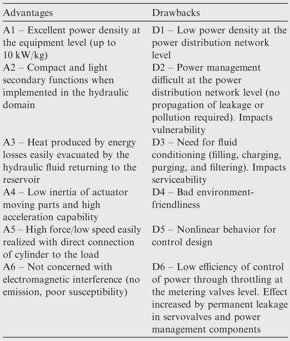
Table 1 Advantages/drawbacks of hydraulic technology.

Table 2 From signal by cables to signal-by-wire for commercial aircraft.17
For signaling,optical fibers are also good candidates to remove electrical wires and make a f l y-by-light(FbL)signaling architecture which facilitates integration(e.g.,16 times less attenuation,8 times lighter,2 times more compact,and bend-ing radius reduced by 15%).17Since 1980,many research programs have dealt with optical data transmission for actuation in fighters,helicopters,and commercial aircraft,including flight tests:e.g.,HOFCAS/AFCAS,24ADOCS,25and FLASH26in United States,OPST27and ACT/FHS28in Europe.For the time being,optical fibers for data transmission have been implemented for less critical functions:110 optical links(1.7 km)on Boeing B787,171 data links(2.4 km)on Airbus A380.29
The ultimate solution for transmitting information consists of using radio waves to make fly-by-wireless(FbWL).Obviously,a total removal of wiring provides significant gains during design,integration,and operation.30The concept has been demonstrated in flight in 2008 for spoiler actuation on the Gulfstream G650 test aircraft.To date,facing the challenges of safety and security,signaling by wireless has been put into service only for non-critical functions like the emergency lighting system for cabin evacuation on Boeing B787.
3.2.Power-by-wire concepts
Very early in the development of aircraft,investigations dealt with the search for new concepts enabling the drawbacks of hydraulic power transmission to be removed or reduced.The candidate concepts are summarized in Fig.4 which starts from all-hydraulic at top and moves to hydraulic-less at bottom.
In conventional hydraulic servo-actuators,as shown in Fig.4(a),hydraulic power is distributed by centralized networks and metered by throttling.The major drawbacks associated with this concept can be partially removed by:
(1)Producing hydraulic power at constant pressure from the electrical network as close as possible to the actuation need,as shown in Fig.4(b).This solution removes partially drawback D1 in Table 1.It has been tested in the late 1970s as a backup hydraulic power source integrated in an actuator to increase survivability of combat aircraft.31More recently,it has been implemented in Airbus A380 then A350 as a local electro-hydraulic generation system(LEHGS)for backup supply of landing gears steering and braking.32
(2)Using displacement control instead of throttling for the control of power of hydraulic motors,as shown in Fig.4(c).When applicable,this concept removes drawback D6 in Table 1.It has been implemented on Airbus A380 for power control units driving flaps and slats.33,34
(3)Reducing the permanent leakage of servovalves by removing the hydraulic pilot stage to make direct drive valves(DDVs).This solution,reducing drawback D6 in Table 1,has been applied to combat aircraft18like Eurofighter and Northrop B2 Saab JAS 39 as well as helicopters35like NH Industries NH90.However,it has not been propagated to commercial aircraft for various reasons,in particular because the permanent leakage helps heat the fluid to avoid excessive pressure losses in pipes at low temperature and DDVs require about 50 times more power at command input that can no longer considered as pure signaling.
Obviously,the potential of evolution of actuation systems remains limited if the benefit of the natural advantages is not taken to electrical power networks and drives,as shown in Table 3.Supplying actuators by electrical wires opens a way to attractive concepts that are detailed in the next sections.
3.2.1.Variable displacement EHA/Fig.4(d)
An electric power source directly supplies an AC motor that drives a variable displacement pump connected to a hydraulic cylinder.This makes a hydrostatic loop.The load is closedloop position-controlled by action on the pump displacement.This design appeared in the late 1930s for airborne gun turrets and then was applied to flight controls of military and commercial aircraft in the 1950s.The concept was investigated again in the 1980s and flight-tested for aileron actuation in the mid-1990s.36–38Although the absence of power electronics was a real advantage,this concept was abandoned for its low efficiency,difficulty to reach thermal equilibrium,and poor hydraulic stiffness.
3.2.2.Fixed displacement EHA/Fig.4(e)
Instead of being controlled by action on the pump yoke,the power is controlled by action on the electrical drive of a fixed displacement pump.This concept has been developed in parallel in USA and Europe,but for different applications.The US programs were dedicated to military aircraft with the purpose to increase aircraft survivability and to facilitate support in operation.NumerousEHA-FD demonstrators(EPAD,

Table 3 Advantages/drawbacks of electrical technology.
EACS,FLASH,and J/IST programs)were developed and flight-tested for flight control actuation of F-15,F-16,and F-18 fighters.39–42Finally,EHA-FD entered into service in 2015 on full-PbW F-35 multirole combat aircraft which have no centralized hydraulic network.In Europe,the development of EHA-FD has addressed commercial aircraft that are penalized by long and wide centralized hydraulic power networks.Research programs started first with aileron actuation of single-aisle aircraft(EGIDE,ELAC,43CVF,and EPICA)and then were extended to larger aircraft(ELISA44and POA45).Finally,the EHA-FD entered into service in doubledeck Airbus A380,initiating their use for the primary flight controls of latest aircraft(Airbus A400M and A350).EHAs were also assessed for application in landing gear extension/retraction(LGER).A key idea was to use a single electropump(electro-hydraulic module or EHM)to supply in sequence different LGER users(doors opening/closing,gear extension/retraction,and locks).It was implemented in the mid-2000s in the frame of the POA research program,46in Japan,47and more recently in the frame of the THERMAE II project.48,49It is worth noting the interest of standardizing EHMs,like servovalves,an activity which started in the late 1990s50and that is under progress at the Society of Automotive Engineers(SAE)to issue soon an Aerospace Recommended Practice(SAE-ARP6154).
3.2.3.EMA/Fig.4(f)
This concept removes totally the hydraulic technology to transmit power and therefore its natural advantages.This explains why the maturation of high-power EMAs for safety-critical functions is not straightforward,having to deal simultaneously with the reliability and the response to failure of electric drives and mechanical power transmission(see Section 4.3).Numerous research and development programs have been conducted for decades covering a wide range of applications.
(1)Space.The short mission duration and the strong requirements of availability in space and weapons applications favored the first developments of EMAs for thrust vector control(TVC).EMAs were already serviced for the manned exploration of the moon in the early 1970s.51,52Later,the feasibility of replacing an HSA by EMAs was studied for the NASA Space Shuttle TVC,53,54missiles TVC,55and crew vehicles.56,57EMAs have now replaced HSAs for TVC of the latest launchers programs like Atlas V in US or Vega in Europe.58,59
(2)Primary flight controls.EMAs for primary flight controls of airplanes have been assessed simultaneously with EHAs for the above-mentioned programs:EMAS,60EPAD,61and ELAC.43Another impulse was given to EMA actuation in Europe in the mid-2000s through consecutive programs:MOET,62,63COVADIS,64and ACTUATION 2015.65Primary flight controls actuators for helicopters are much more critical as the load positioning cannot be lost for more than a very few milliseconds.Electromechanical actuation was investigated in the HEAT project66for the Merlin EH101 helicopter but flight tests were cancelled due to a lack of demonstrated safety during ground tests.More recently,the HEMAS project67,68aimed at demonstrating a TRL5.EMAs are also potentially attractive to implement individual blade control(IBC)or higher harmonic control(HHC)that reduces noise and vibration while improving aerodynamic efficiency of rotors.IBC EMAs were tested on ground on a Sikorsky CH-53G69and developed for the PROJECT ZERO unmanned convertiplane.70For the time being,EMAs have not entered into service for primary flight control applications,mainly due to their risk of jamming that raises real issues regarding their back-drivability.
(3)Secondary flight controls.Jamming is not a strong issue for most secondary flight controls where the preferred response to failure is of fail-frozen type.Moreover,hydraulically-supplied solutions already involve a significant amount of mechanical transmission devices for flaps,slats,and trim horizontal stabilizers:spur gears,geared rotary actuators,brakes,speed summing through differential,clutches,no-back,etc.For this reason,replacing hydraulic motors by electric motors is not so challenging if the same concepts for mechanical transmission are kept.Consequently,taking benefits of the maturation of electric drives,research projects addressed EMA actuation for secondary flight controls in the 2000s.The research project DEAWS71dealt with the replacement of a centralized power drive by distributed actuation of high lift devices to offer new options for improving aerodynamics through differential steering.The AFC program launched by Gulfstream flighttested EMAs-driven spoilers.72
(4)Landing gears.Landing gears require multiple transient or pulsed actuation functions(doors,extension/retraction,locks,steering,and braking).Major arguments speak in favor of PbW for LGER.For example,the nose landing gear requires long hydraulic pipes because it is located far from the hydraulic power centers,but it is close to the electrical power center.For brakes,hydraulic fluid may also ignite fire in case of leakage of hoses if it comes to high-temperature brakes.However,two major issues are to be fixed by using EMAs.Firstly,extension/retraction is characterized by the need to enable free-fall in case of failure(back-driving is ensured by gravity and airload).Secondly,the control of extension/retraction in hydraulics is extremely simple:on-off control of a directional valve for up or down,fixed flow limiters to limit speed,and fixed snubbing for absorbing the landing gear kinetic energy when end-stops are reached.In PbW actuation,a motor needs power electronics and associated command electronics to generate and apply the motion profile versus time,in order to generate the corresponding motor voltages and to reduce speed before endstops.It appears that this second issue is simpler to fix than the first one that requires the extension/retraction actuator to be tolerant to jamming and to provide sufficient damping during free-fall.This is why most of the research projects like MELANY,73CISACS,74and ARMLIGHT mainly dealt with tolerance to jamming.Braking through EMAs is challenged by the high closed-loop dynamics that is required for antiskid and by the harsh environment constraints(in particular thermal).It has been investigated in the frame of the EABSYS research program75that matured to enter into service on Boeing B787 and Bombardier CSeries.76Landing gear steering has also to meet strong requirements and constraints:response to failure shall be fail-passive to allow self-alignment of the wheels as well as damping in any mode(normal or failed)to avoid Shimmy.Steering by EMAs has also been investigated,in particular in Europe for commercial aircraft through the DRESS,77ELGEAR,71and MELANY projects.
(5)Engines.Engines also involve actuation functions for thrust reverse,inlet guide vanes(IGVs),and engine doors for maintenance.Airbus A380 introduced EMAs in its electrical thrust reverser actuation system(ETRAS).IGVs are also good candidate for EMAs,but the high temperature at which they have to operate most of the time still remains a barrier.
3.2.4.Hybrid designs
Combining the concepts mentioned above is an interesting option to make actuators more reliable and available through dissimilarity.As illustrated in Fig.4,hybridization can be implemented in different manners:
(1)Electro-hydrostatic backup actuator(EBHA).It is interesting to make an actuator redundant and more available by combining two dissimilar power sources.The advantages of hydraulics(in particular A1,A2,and A5 in Table 3)can be kept by using a hydraulic cylinder that is either fed by a servovalve(HSA concept)or by an EHM(EHA concept).As the service life of EHA pumps is still limited,the logical solution consists of using the HSA concept for the normal mode and the EHA for the backup mode.By the way,only one mode is active at a given time,making an ‘exclusive or” function between the HSA and EHA modes.The actual mode is engaged by a solenoid mode selection valve that connects the cylinder either to the servovalve(HSA mode)or to the EHM(EHA mode).If required,a damping mode can be added to make the actuator fail-passive in case of failure of both power channels.The EBHA concept was introduced on Airbus A38078and propagated to A400,A350,and Gulfstream G650.Table 4 lists the uses of EHAs and EBHAs in in-service aircraft.
(2)Electro-assisted hydrostatic actuator(EAHA).The concept of the EBHA can be modified in order to enable both the HSA and EHA modes simultaneously(logical‘inclusive or” function).In this case,flows are summed to the cylinder and the EHM boosts the HSA during peak power demands or in case of partial loss of hydraulic power.This design,tested in the frame of the POA project,can be used efficiently to downsize the hydraulic network while increasing actuator availability.
(3)Electro-backup mechanical actuator(EBMA).Electromechanical actuation can be combined with hydraulic actuation to produce a backup mode with dissimilar sources of power.In this case,the rod of the hydraulic cylinder contains a nut-screw device that can be mechanically driven by an electric motor.This concept has been put into service for the landing gear doors actuation of the Airbus A400M military transporter.73
(4)Passive hydraulic backup EMA.As mentioned above,one of the issues for the LGER function lies in dissipating energy during free-fall.Opposite to the EBMA,this time,the translating part of an EMA nut-screw system can also play the role of a piston that will force fluid to flow through a hydraulic resistance during landing gear extension.This design has been investigated in the frame of the CISACS project.
Hybridization can also be performed by using separate actuators of different technologies,e.g.,EHA/HSA or EMA/HSA.This solution is attractive because it increases dissimilarity and enables more electrical actuation to be progressively introduced with the removal of one or two centralized hydraulic power networks.If the actuators have to drive a single load,a special attention has to be paid to force fighting due to the difference in the static and dynamic behaviors of the associated technologies.79–81
4.Challenges to be taken for PbW actuation
To be placed in the front line and extensively used in aerospace for high-power safety-critical applications,PbW actuators still need to be improved in terms of cost,envelope,mass,reliability,and service life.This concerns all domains:power electronics,motors,and mechanical transmission.
4.1.Power electronics
Of course,motor control electronics,motor power drive,and electric motors generate a lot of research activities to take the best of the opportunities offered by the electrical technology.Among all the directions of investigation in power electronics,one can mention:
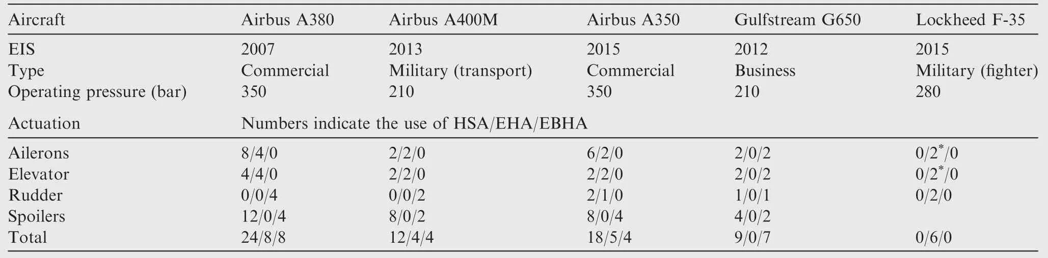
Table 4 In-service aircraft using EHAs and EBHAs for flight controls.
4.1.1.Removal of the DC link
In common designs,the power delivered to an actuator motor is metered by an inverter that is supplied at a contact DC voltage.This so-called DC-link is got by rectification of a 3-phase AC supply network.Two options can reduce the number of elements associated with EMAs.The first one mutualizes a high-voltage DC-link(e.g.,540 V or ‘double voltage”)for several users in order to remove rectifiers,filters(input,line,and motor),and preload,82and to enable energy regeneration when driven loads become aiding.The other solution removes the need for the DC link by connecting the motor to the AC supply through a matrix converter.83,84
4.1.2.Increase of service voltage of power switches85
For a given power,this will enable reducing the current to be carried by the wires and windings,and consequently save mass and/or conduction losses.
4.1.3.Improvement of cooling
As already mentioned,opposite to HSAs,PbW actuators cannot take advantage of the hydraulic fluid returning to the reservoir to evacuate the heat generated by energy losses.When natural convention is used,the heat exchange factor is limited to a very few W/(m2·°C).Forcing convection requires power to generate the airflow around an actuator and may be detrimental to reliability.Resort to heat pipes,which implement twophase cooling,is already applied for space applications,but still looked at with interest for aircraft.86
4.2.Motors design and control
For the time being,actuation for aerospace essentially uses brushless motors,as long as variable/switched reluctance motors are not sufficiently mature or attractive.Brushless motors bring a huge panel of options to designers that can be played with:
(1)Number of phases,poles,and slots.87
(2)Magnet assembly.Magnet can be surface-mounted(with or without step skewing,88buried,with flux concentration in a V or double layer,89in a Halbach array).90
(3)Type of winding.With or without overlap,distributed or concentrated,a single or double layer.91
(4)Shape of slots.Full,empty,closed,bifurcated,straight or skewed,segmented or not.90,92
(5)Type of association with power electronics.93
These choices impact both power density and extension of torque/velocity capability,thermal/magnetic/electric segregation,torque ripple,and iron losses.94
In practice,the powers of electric motors used in PbW actuators range between a few kW(e.g.,5 kW for single-aisle aileron actuators)and some 10 kW(large aircraft rudder actuators or space launcher thrust vector control actuators).Due to the mass constraints,these motors develop low torque to save heavy materials(copper for windings,magnets and laminates for magnetic fields).For a given power,this is therefore compensated by high angular velocities which range typically between 6000 and 15000 r/min.17
4.3.Mechanical transmission
More electrical actuation generates a lot of research activities dealing with mechanical transmission,in particular in the following directions.
4.3.1.Lubrication
One first reason of focusing on lubrication concerns loaded contacts between moving pieces(bearings,joints,power transmission devices)that make up generally the weakest points of failure.Sizing such devices is well established for applications where there is no speed reversal and the mean velocity is high,e.g.,hydropower plants.Therefore,contacts between rolling solids are well lubricated and there is no risk of sliding due to inertia effects under speed reversals.Oppositely,flight control or landing gear steering actuators which are positioncontrolled operate in the vicinity of the null speed with high accelerations,within a wide temperature range and under loads that can also reverse.At low velocity or high temperature(low lubricant viscosity),contacts may operate in boundary lubrication conditions:wear becomes more severe as the lubricant thickness between moving parts decreases and the friction coefficient increases.
4.3.2.Secondary functions
As already mentioned,several secondary functions(e.g.,damping,freeing or locking the load in position,overload protection,snubbing at endstops)have to be performed in addition to pure power transmission and transformation.In EHAs,this is not an issue as conventional and efficient hydraulic solutions can be kept.Oppositely,EMAs designers have to find means to perform these functions either mechanically or electrically.It is tempting to implement them at the motor control level as it essentially requires additional lines of code.Unfortunately,this type of solution does not work if the electric(signal and power)and electromechanical(motor)power elements have failed.Moreover,the motor inertia and the friction losses in the mechanical transmission often make the motor current an inaccurate representative of the force transmitted to the load.This often cancels the option of using the motor current for overload protection.Addition of a force sensor,on either the actuator rod or the actuator housing,may enable active damping.95
4.3.3.Jamming
Fortunately,there are many options to deal with reliability in the electric and electromagnetic domains with resort to redundancies:fault-tolerant power electronics,96,97redundant electronics/motor architectures,93or motor topology.98In the mechanical domain,a strong issue is raised when the expected response of an actuator to jamming is fail-passive or failfunctional.A first solution consists of developing mechanical power transmission devices that are jam-tolerant99to ensure safe-life operation.For other solutions,it is generally required that de-clutching a jammed actuator can be performed under load.A passive solution consists of shearing a mechanical fuse(e.g.,pins)in case of excessive transmitted load.It has been implemented with limited success.66Active solutions declutch the jammed path under command.Pyrotechnic has been addressed for helicopters flight control actuators100and then abandoned because it cannot be tested,as the former one does,to check for availability.More recent solutions are electromagnetically or electromechanically supplied.101–104When an actuator shall be fail-functional in case of internal jamming,two mechanical paths are required.The first candidate arrangement sums the forces of the two channels(e.g.,Ref.101)while the second sums the displacements of the two channels,e.g.,by nesting two nut-screws to make a telescopic jack(e.g.,Ref.102).Beside all these solutions,health and usage monitoring(HUM)is more and more considered as an alternative to make an actuator resistant or tolerant to jamming.94It intends to early detect the presence of a fault(diagnosis)and to calculate the remaining service before the fault turns into failure(prognostics).This approach starts to be well established for the electric domain,but is not so easy to be applied to jamming,firstly due to a lack of means to early detect a fault in a real aircraft environment,and secondly for a lack of models for predicting the evolution of the fault into jamming.
4.3.4.Anti-rotation function
In hydraulic cylinders,the rod is linked to the housing though a cylinder pair joint.This introduces a degree of freedom that can compensate the deformations in the kinematic chain involving the holding frame,the actuator,and the driven load.Oppositely,electromechanical linear actuators require anti-rotation functions for the housing and the rod to hold the reaction torques generated by the nut-screw function(plus those of the motor and the mechanical elements depending on the actuator topology).17These anti-rotation functions can be integrated to an actuator(e.g.,slider or compass)or performed by the above-mentioned kinematic chain(e.g.,trunnions or anti-rotation tabs).
In order to illustrate the evolution toward all electrical actuators,Fig.5 gives a panel of in-service actuators for commercial and military aircraft and launchers.
5.Conclusions
(1)The huge and rapid progresses in electrical drives create a high pressure to replace conventional actuators with electrically-signaled and electrically-powered actuators.However,their use in safety-critical applications is not so simple.Sometimes forgotten,the natural advantages of hydraulics and the specific drawbacks of electric drives make this replacement not straight-forward,especially when secondary functions,thermal balance,and reliability are considered.
(2)It has taken more than two decades to fully replace mechanical signaling with signal-by-wire.Considering the time scale of aircraft production and service,power-by-wire and hydraulic-less actuation has just started to appear and has a high potential of improvement.One of the main difficulties lies in evaluating the overall gain at the stake-order level(passenger,airline,air traffic,and aircraft manufacturer)and in making right choices for designs that will still be flying in 60 years.From this point of view,today it appears that a pragmatic approach can be found with concepts that combine the best of hydraulic and electric.By this process,hydraulic can be removed progressively by incremental changes as the challenges of all-electric actuation for aerospace are being solved with mature solutions.This will also require changes in airframe design,sizing,power distribution,and management to take the best of the electrical technology.
1.Hufenbach W,Helms O,Ulbricht A,Garthaus C.Lightweight hydraulic pipes and actuators in innovative multi-material design.Proceedings of the 4th international conference on recent advances in aerospace actuation systems and components;2010 May 5–7;Toulouse,France;2010.p.66–71.
2.Kausch M,Meyer M,Kroll L,Baumbach V,Novel hydraulic lightweight manifolds in aviation.Proceedings of the 4th international conference on recent advances in aerospace actuation systems and components;2010 May 5–7;Toulouse,France;2010.p.56–9.
3.Guerrier P,Zazynski T,Gilson E,Bowen C,Additive manufacturing for next generation actuation.Proceedings of the 7th international conference on recent advances in aerospace actuation systems and components;2016 Mar 16–18;Toulouse,France;2016.p.42–7.
4.Hummel G,Konrad T,Harten O,Altmann A,Schubert F,Kroll L.Additive manufacturing for high pressure hydraulic valve Manifold of Airbus A380 spoiler actuator.Proceedings of the 7th international conference on recent advances in aerospace actuationsystems and components;2016 Mar 16–18;Toulouse,France;2016.p.48–54.
5.Liscouet J,Orieux S,Budinger M,Mare´J-C.Electromechanical nose wheel steering actuator study of high reliability architectures.Proceedings of SAE A-5 aerospace landing gear systems;2008 Apr 8–10;Toulouse,France.2008.
6.MAI T.Technology Readiness Level[Internet].Washington,D.C.:NASA;2012[cited 2012 Oct 29].Available from:https://www.nasa.gov/directorates/heo/scan/engineering/technology/txt_accordion1.html.
7.Liscoue¨t-Hanke S.A model-based methodology for integrated preliminary sizing and analysis of aircraft power system architecture[dissertation].Toulouse:INSA;2008.
8.Comes M.L’A380,Nouveaute´s techniques ou techniques nouvelles.Proceedings of the conference association aeronautique et astronautique de France;2005 Jan 7;Toulouse,France;2005
9.Mare´J-C.Aerospace actuators volume 1:Needs,reliability and hydraulic power solutions.1st ed.London:John Wileyamp;Sons,Inc.;2016.
10.Mare´J-C,Budinger M.Comparative analysis of energy losses in servo-hydraulic,electro-hydrostatic and electro-mechanical actuators.Proceedings of the 11th scandinavian international conference on fluid power;2009 Jun 2–4;Linko¨ping,Sweden;2009.
11.Mare´J-C,Moulaire P.Expert rules for the design of position control of electrohydraulic actuators.Proceedings of the 6th scandinavian international conference on fluid power;1999 May 26–28;Tampere,Finland;1999.p.1267–80.
12.Yao J,Jiao Z,Ma D.Extended-state-observer-based output feedback nonlinear robust control of hydraulic systems with backstepping.IEEE Trans Ind Electron2014;61(11):6285–93.
13.Yao J,Jiao Z,Ma D,Yan L.High-accuracy tracking control of hydraulic rotary actuators with modeling uncertainties.IEEEASME Trans Mechatron2014;19(2):633–41.
14.Van Den Bossche D.The evolution of the Airbus primary flight control actuation systems.Proceedings of the 3rd internationales fluidtechnishes kolloquium;2002 March 5–6;Aachen Germany;2002.p.355–66.
15.Airbus.Flight airworthiness support technology.Airbus Technical Magazine;Special edition A350 XWB;2013.
16.Stiles LR,Freisner AL,Mayo J,Landis KH,Kothmann BD.Impossible to resist:the development of rotorcraft Fly-by-Wire technology.American helicopter society international 60th annual forum;2004 June 7–10;Baltimore,USA;2004.
17.Mare´J-C.Aerospace actuators Volume 2:Signal and power by wire.1st ed.London:John Wileyamp;Sons,Inc;2017.
18.Schaeffer WS,Inderhees LJ,Moynes JF.Flight control actuation for the B-2 advanced technology bomber.Proceedings of the aerospace hydraulics and systems international conference;1993 Sep 29-30;London,UK;1993.p.23–32.
19.Yeh YC.Triple-triple redundant 777 primary flight computer.Proceeding of IEEE aerospace applications conference;1996 Feb 3–10;Aspen,USA;1996.p.293–307.
20.Kulshreshtha A.Remote actuation control system:aircraft flight control for hydraulic-servo and electric actuation.Proceedings of the international conference on recent advances in aerospace actuation systems and components;2007 Jun 13–15;Toulouse,France;2007.p.155–62.
21.O’brien J,Kulshreshtha A.Distributed and remote control of flight control actuation using power line communications.IEEE/AIAA 27th digital avionics systems conference;2008 Oct 26–30;Saint Paul,USA.2008
22.De´gardin V,Simon EP,Morelle M,Lie´nard M,Degauque P,Junqua I,et al.On the possibility of using PLC in aircraft.IEEE international symposium on power line communications and its applications;2010 March 28–31;Rio de Janeiro,Brazil;2010.p.337–40.
23.Morra J.Fiber optics transmit data and power over same cable[Internet].Electronic Design;2016[cited 2016 Jan 29].Available from:http://electronicdesign.com/power/.
24.Kohnhorst LL,Magnacca DA.Design and test of a hydra-optic flight control actuation system(HOFCAS)concept.Washington:Navair Devceim;1980.Report No.:79156–60.
25.Terry JL,Tdickinson JD,Jerauls GD.The advanced digitaloptical control system(ADOCS)user demonstration program.Washington:Army AVSCOM;1989.Report No.:TM-89-D-2.
26.Zavala E.Fiber optic experience with the smart actuation system on the F-18 systems research aircraft.Washington:NASA;1997.Report No.:TM-97-206223.
27.Faulkner A.Smart actuator systems:a practical solution.Proceedings of the aerospace hydraulics and systems international conference;1993 Sep 29–30;London,UK;1993.p.123–32.
28.Bickel N,Butter U,Hammerlindl M,Eichberger W.Getting a primary f l y-by-light control system into flight.American helicopter society 59th annual forum;2003 May 6–8;Phoenix,USA;2003.
29.Bouyssou S.Optical fiber on aircraft-When the light speed serves data transmission.Airbus Technical Magazine;2011:14–20.
30.Elgezabal O.Fly-by-wireless(FBWSS):Benefits,risks sand technical challenges.CANEUS Fly-by-Wireless Workshop;2010 Aug 24;Orono,USA;2010.
31.Hooker DS,Kisslinger RL,Smith GR,Smyth S.Survivable flight control system interim report no.1-Studies,analyses and approach.Washington:United States Air Force;1971.Report No.:AFFDL-TR-71-20.
32.Dellac S,Ternisien D.Airbus 380 ‘Electro-Hydraulic back-up architecture”for braking and steering systems.Proceedings of the 2nd international conference on recent advances in aerospace actuation systems and components;2004 Nov 24–26;Toulouse,France;2004.p.103–8.
33.Bowers A.A380 hydraulic slat drive channel.Proceedings of the 2nd international conference on recent advances in aerospace actuation systems and components;2004 Nov 24–26;Toulouse,France;2004.p.91–6.
34.Hauber B,Fleddermann A.Variable displacement hydraulic motors in the A380 high lift system.SAE A6 Aerospace Actuation,Control and Fluid Power Systems Committee.USA;2005.
35.Nguyen T,De La Chevasnerie A,Sandler S.Direct drive servo valve.Proceedings of the 2nd international conference on recent advances in aerospace hydraulics;2004 Nov 24–26;Toulouse,France;2004.p.73–8.
36.Acee H.The integrated actuator package approach to primary flight control.SAE aerospace Atlantic;1992 Apr 7–10.Dayton,USA;1992.
37.Alden R.Flight demonstration,evaluation and proposed applications for various all electric flight control actuation systems concepts.AIAA aerospace design conference;1993 Feb 16–19;Irvine,USA;1993.
38.Bildstein M.EHA for flight testing on Airbus A321-Power losses of f i x pump EHA versus variable pump EHA.Proceedings of the international conference on recent advances in aerospace hydraulics;1998 Nov 24–26;Toulouse,France;1998.p.101–3.
39.Smith R.Joint strike fighter integrated subsystems technology(J/IST)demonstration program overview.SAE Transactions on Journal of Aerospace1996;105(1):962259.
40.Trosen D,Cannon BJ.Electric actuation and control system.Proceedings of the 31st energy conversion engineering conference;1996 Aug 11–16;Washington,USA;1996.p.197–202.
41.Navarro R.Performance of an electro-hydrostatic actuator for the F-16 systems research aircraft.Washington:NASA;1997.Report No.:TM-97-206224.
42.Roach JM.FLASH electrohydrostatic actuation modelling,analysis and test results.SAE Transactions on Journal of Aerospace1997;106(1):971234.
43.Del Core A.Advances in onboard system technology.1st ed.Chichester:John Wileyamp;Sons Ltd;1996.p.195–248.
44.Moorhouse D,Maxwell C,Bildstein M.Electro hydrostatic actuator for primary flight control of very large aircraft.Proceedings of the 1st international conference on recent advances in aerospace actuation systems and components.2001 Jun 13–15;Toulouse,France;2001.p.101–3.
45.Dorkel A,Biedermann O,Wennmacher G.Theoretical validation and experimental verification of the electrically assisted hydraulic actuator concept.Proceedings of the 3rd international conference on recent advances in aerospace actuation systems and components.2007 Jun 13–15;Toulouse,France;2007.p.15–9.
46.Greissner C,Carl U.Control of an electro-hydrostatic actuation system for the nose landing gear of an all-electric aircraft.Proceedings of the 2nd international conference on recent advances in aerospace actuation systems and components;2004 Nov 24–26;Toulouse,France;2004.p.9–13.
47.Takahashi N,Kondo T,Takada M,Masutani K,Okano S,Tsujita M.Development of prototype electro-hydrostatic actuator for landing gear extension and retraction system.Proceedings of the 7th JFPS international symposium on fluid power;2008 Sep 15–18.Toyama,Japan.2008.p.165–8.
48.Davidon W,Roizes J.Electro-hydrostatic Actuation System for aircraft landing gear actuation.Proceedings of the 5th international workshop on aircraft systems technologies;2015 Feb 24–25;Hamburg,Germany;2015.p.3–12.
49.Elliott N,Linforth S,Moore C.Thermae II(Main landing gearamp;door EH actuation system)-Integration and testing.Proceedings of the 7th international conference on recent advances in aerospace actuation systems and components;2016 Mar 16–18;Toulouse,France;2016.p.112–7.
50.Arnaud A.An approach to EHA standardization.Proceedings of the international conference on recent advances in aerospace hydraulics;1998 Nov 24–26;Toulouse,France;1998.p.105–15.
51.Tutt GE,Jansen JA.Dynamics of the Apollo electromechanical actuator.J Space Rockets1968;5(5):541–6.
52.Mahon W.Apollo experience report-Guidance and control systems:CSM service propulsion system gimbal actuators.Washington:NASA Technical Note;1975.Report No.:D-7969.
53.Edge JT.An electromechanical actuator technology development program;1978.Report No.:SAE Technical Paper 780581.
54.Teske D,Faulkner D.Electromechanical flight control servoactuator.Proceedings of intersociety energy conversion engineering conference;1993 Aug 21–26;Orlando,USA;1993.p.1021–5.
55.Fulmer C.40 HP Electro-mechanical actuator.Washington:NASA contractor;1996.Report No.:198509.
56.Hagen J,Moore L,Estes J,Layer C.The X-38 V-201 flap actuator mechanism.Proceedings of the 37th aerospace mechanisms symposium;2004 May 19–21;Johnson Space Center,USA;2004.p.377–90.
57.Verhoeven D,De Coster F.Electro-mechanical actuators(EMA’s)for space applications.Proceedings of the 15th European space mechanismsamp;tribology symposium;2013 Sep 25–27;Noordwijk,The Netherlands;2013.
58.Carnevale C,Resta PD.Vega electromechanical thrust vector control development.Proceedings of the 43rd AIAA/ASME/ASEE joint propulsion conference and exhibit;2007 Jul 8–11;Cincinnati,USA;2007.p.10.
59.Vanthuyne T.An electrical thrust vector control system for the VEGA launcher.Proceedings of the 13th European space mechanisms and tribology symposium.2009 Sep 23–25.Vienna,Austria;2009.
60.Norton WJ.Advanced electromechanical actuation system(EMAS),Flight Test.Washington:Air Force Wright Aeronautical Laboratories;1986.Report No.:AD-A176-148.
61.Kopala DJ,Doell C.High performance electromechanical actuation for primary flight surfaces(EPAD program results).Proceedings of the 1st international conference on recent advancesin aerospace actuation systems and components;2001 Jun 13–15;Toulouse,France;2001.p.71–6.
62.De La Chevasnerie A,Grand S,Legrand B,Sandler S.Electromechanical actuator/MOET project.Proceedings of the 4th international conference on recent advances in aerospace actuation systems and components;2010 May 5–7;Toulouse,France;2010.p.83–7.
63.Jomier T.More open electrical technologies.AF-DEL-MOET Consortium Partners;2009.Report No.:0001-09-R1.
64.Derrien J-C,Tieys P,Senegas D,Todeschi M.EMA aileron COVADIS development.SAE aerospace technology conference and exposition;2011 Oct 18;Toulouse,France;2011.
65.Grand S,Balducci G,Fervel M,Wenfling M.Actuator control:a successful modular multi-application approach or actuation 2015 and beyond.Proceedings of the 7th international conference on recent advances in aerospace actuation systems and components;2016 Mar 16–18;Toulouse,France;2016.p.60–5.
66.Wright P.Helicopter electro-mechanical actuation technology.Proceedings of colloquium on electrical machines and system for the more electric aircraft.1999 Nov 9;London,UK;1999.p.131–6.
67.Seemann S,Christmann M,Janker P.Control and monitoring concept for a fault-tolerant electromechanical actuation system.Proceedings of the 5th international conference on recent advances in aerospace actuation systems and components.2012 Jun 13–14;Toulouse,France.2012.p.39–43.
68.Rottach M,Gerada C,Wheeler P.Helicopter EMA system:Electrical drive optimization and test.Proceedings of the 6th international conference on recent advances in aerospace actuation systems and components;2014 Apr 2–3;Toulouse,France;2014.p.9–13.
69.Fuerst D,Neuheuser T.Development,prototype production and testing of an electromechanical actuator for a swashplateless primary and individual helicopter blade control system.Proceedings of the 1st workshop on aircraft systems technology;2007 Mar 29–30;Hamburg,Germany;2007.p.7–19.
70.Gianfranceschi M,Jacazio G,Wang J.High bandwidth electromechanical actuator for swashplateless blade control system.Proceedings of the 6th international conference on recent advances in aerospace actuation systems and components;2014 Apr 2–3;Toulouse,France;2014.p.1–8.
71.Bennett JW.Fault tolerant electromechanical actuators for aircraft[dissertation].Newcastle:Newcastle University;2010.
72.Whitley C,Ropert J.Development,manufactureamp;flight test of spoiler EMA system.Proceedings of the 3rd international conference on recent advances in aerospace actuation systems and components;2007 Jun 13–15;Toulouse,France.2007.p.215–20.73.Chevalier PY,Grac S,Liegeois PY.More electrical landing gear actuation systems.Proceedings of the 4th international conference on recent advances in aerospace actuation systems and components;2010 May 5–7;Toulouse,France;2010.p.9–16.
74.Mare´J-C.Combining hydraulics and electrics for innovation and performance improvement in aerospace actuation.Proceedings of the 12th scandinavian international conference on fluid power;2011 May 18–20;Tampere,Finland;2011.p.255–70.
75.CollinsA,EABSYS electrically actuated braking system.Proceedings of colloquium on electrical machines and systems for the more electric aircraft.1999 Nov 9;London,U.K;1999.p.41–5.
76.Chico P.Electric brake.Proceedings of the 6th international conference on recent advances in aerospace actuation systems and components;2014 Apr 2–3;Toulouse,France;2014.p.25–8.
77.Iordanidis G,Dellac S.DRESS:Distributed and redundant electro-mechanical nose gear steering system.SAE International Journal of Aerospace2010;2(1):46–53.
78.Biedermann O,Bildstein M.Development,qualification and verification of the A380 spoiler EBHA.Proceedings of the 2nd international conference on recent advances in aerospace actuationsystems and components;2004 Nov 24–26;Toulouse,France;2004.p.97–101.
79.Cochoy O,Hanke S,Carl UB.Concepts for position and load control for hybrid actuation in primary flight controls.J Aerosp Sci Technol2007,11(2–3):194–201.
80.Qi H,Fu Y,Mare´J-C,Lang Y,Wang L.Investigation in hybrid actuation for duplex actuators operating in active/no-load modes.Proceedings of the 2009 IEEE/ASME conference on advanced intelligent mechatronics;2009 Jul 14–17,Singapore.2009.p.993–7.
81.Wang L,Mare´J-C,Fu Y.Investigation in the dynamic force equalization of dissimilar redundant actuation systems operating in active/active mode.28th International Congress on Aerospace Sciences;2012 Sep 23-28;Brisbane,Australia;2012.p.78.1–8.
82.Langlois O.Conception d’un reseau de secours electrique pour l’aeronautique[dissertation].Toulouse:INP;2006.
83.Empringham L,Kolar JW,Rodriguez J,Wheeler PW,Clare JC.Technological issues and industrial application of matrix converters:a review.IEEE Trans Ind Electron2013;60(10):4260–71.
84.Wheller PW.Et AL.Design and reliability of a rudder EMA with an integrated permanent magnet machine and matrix converter drive.Proceedings of the 3rd international conference on recent advances in aerospace actuation systems and components;2007 Jun 13–15;Toulouse,France;2007.p.21–6.
85.Cougo B,Carayon J-P,Dos Santos V,Hilal A,Billard T.Impacts of the use of SiC semiconductors in actuation systems.Proceedings of the 7th international conference on recent advances in aerospace actuation systems and components;2016 Mar 16–17;Toulouse,France;2016.p.201–6.
86.Lecleir M,Barremaecker L.Two phase cooling system for aircraft actuators.Proceedings of the 6th international conference on recent advances in aerospace actuation systems and components.2014 Apr 2–3;Toulouse,France;2014.p.160–6.
87.Dogan H,Wurtz F,Foggia A,Garbuio L.Analysis of slot-pole combination of fractional-slots PMSM for embedded applications.Aegean conference on electrical machines and power electronics;2011 September;2011.p.627–31.
88.Saha S,Cho YH.Design of 3-step skew BLAC motor for better performance in electric power.International Journal of Mechanical Aerospace,Industrial Mechatronic and Manufacturing engineering2015;9(7):1264–9.
89.Akiki P,Hage H M,Vannier J-P,Dessante P,Daguse B,Bensetti M.Re´duction des ondulations de couple d’un moteur a`aimants en multi-V et bobinage sur dents.Symposium de Genie Electrique;2016 Jun 7–9;Grenoble,France.2016.
90.Gieras JF.Permanent magnet motor technology:design and applications.3rd ed.Boca Raton:CRC Press;2010.
91.El Refais AM.Fractional-slot concentrated windings synchronous permanent magnet machines:opportunities and challenges.IEEE Trans Ind Electron2010;57(1):107–212.
92.Do¨nnemzer Y,Ergene LT.Skewing effect on interior type BLDC motors.Proceedings of 19th international conference on electrical machines;2010 Sep 6;Rome,Italy.2010.p.5.
93.Cao W,Mecrow BC,Atkinson GJ,Bennett JW,Atkinson DJ.Overview of electric motor technologies used for more electric aircraft(MEA).IEEE Trans Ind Electron2012;59(9):3523–31.
94.Fu J,Mare´J-C,Fu Y.Modelling and simulation of flight control electromechanical actuators with special focus on model architecting,multidisciplinary effects and power flows.Chin J Aeronaut.2017;30(1):47–65.
95.Wang L,Mare´J-C.A force equalization controller for active/active redundant actuation system involving servo-hydraulic and electro-mechanical technologies.Proc Inst Mech Eng Part G-J Aerosp Eng2014;228(10):1768–87.
96.Argile RN,Meerow BC,Atkinson DJ,Jack AG,Sangha P.Reliability Analysis of Fault Tolerant Drive Topologies.Proceedings of 4th IET conference on power electronics,machines and drives;2008 Apr 2–4;York,USA;2008.p.1–15.
97.Welchko BA,Lipo TA.Jahns TM,Schulz SE.Fault tolerant three-phase AC motor drive topologies:a comparison of features,cost,and limitations.IEEE Trans Power Electr2004;19(4):1108–16.
98.Alexandre P,Telteu D,Baudart F,Labrique F,Matagne E.Failure operation of a multiphase drive for an electro mechanical actuator.Proceedings of the 4th international conference recent advances in aerospace actuation systems and components;2010 May 5–7;Toulouse,France;2010.p.111–5.
99.Babinski J.Jam tolerant electro-mechanical actuators for aircraft flight and utility control.Proceedings of the 4th international conference on recent advances in aerospace actuation systems and components;2010 May 5–7;Toulouse,France;2010.p.42–6.
100.Naubert A,Crhistmann M,Janker P,Binz H.Anti-jamming mechanism for electromechanical actuators.Proceedings of the 4th international workshop on aircraft system technologies.2013 Apr 23–24;Hamburg,Germany;2013.p.139–47.
101.Bildstein M.A built-in jam release device for electromechanical actuators in flight control.Proceedings of the 6th internationalconference on recent advances in aerospace actuation systems and components.2014 Apr 2–3;Toulouse,France;2014.p.105–8.
102.Jimenez A,Novilo E,Aguado E,Morante E.Electromechanical actuator with anti-jamming system for safety critical aircraft applications.Proceedings of the 5th international conference on recent advances in aerospace actuation systems and components;2012 Jun 13–14;Toulouse,France;2012.p.77–83.
103.Jimenez A,Novillo E,Aguado F,Iasa J,Eguizabal I,Lopez I.Electromechanical actuator with anti-jamming system for safety critical applications.Proceedings of the 7th international conference on recent advances in aerospace actuation systems and components;2016 Mar 16–18;Toulouse,France;2016.p.27–32.
104.Naubert A,Binz H,Bachmann M,Christmann M,Toto S,Perni F.Disconnect device design options for jam-tolerant electromechanical actuators.Proceedings of the 7th international conference on recent advances in aerospace actuation systems and components;2016 Mar 16–18;Toulouse,France;2016.p.187–192.
25 December 2016;revised 6 February 2017;accepted 10 February 2017
 CHINESE JOURNAL OF AERONAUTICS2017年3期
- CHINESE JOURNAL OF AERONAUTICS的其它文章
- Real-time solution of nonlinear potential flow equations for lifting rotors
- Suggestion for aircraft flying qualities requirements of a short-range air combat mission
- A high-order model of rotating stall in axial compressors with inlet distortion
- Experimental and numerical study of tip injection in a subsonic axial flow compressor
- Dynamic behavior of aero-engine rotor with fusing design suffering blade of f
- Experimental research of air-throttling ignition for a scramjet at Ma 6.5