Simulation of two-dimensional interior ballistics model of solid propellant electrothermal-chemical launch with discharge rod plasma generator
Yn-jie Ni,Yong Jin,Ninki Cheng,Chun-xi Yng,Hi-yun Li,*,Bo-ming Li,
aNational Key Laboratory of Transient Physics,Nanjing University of Science and Technology,Nanjing 210094,Jiangsu,China
bChina Academy of Ordnance,100089,Beijing,China
Simulation of two-dimensional interior ballistics model of solid propellant electrothermal-chemical launch with discharge rod plasma generator
Yan-jie Nia,Yong Jina,Niankai Chengb,Chun-xia Yanga,Hai-yuan Lia,*,Bao-ming Lia,b
aNational Key Laboratory of Transient Physics,Nanjing University of Science and Technology,Nanjing 210094,Jiangsu,China
bChina Academy of Ordnance,100089,Beijing,China
A R T I C L E I N F O
Article history:
22 April 2017
Accepted 8 May 2017
Available online 12 May 2017
Electrothermal-chemical launch
Interior ballistics simulation
Two-phase flow
Two-dimensional model
Instead of the capillary plasma generator(CPG),a discharge rod plasma generator(DRPG)is used in the 30 mm electrothermal-chemical(ETC)gun to improve the ignition uniformity of the solid propellant.An axisymmetric two-dimensional interior ballistics model of the solid propellant ETC gun(2D-IB-SPETCG) is presented to describe the process of the ETC launch.Both calculated pressure and projectile muzzle velocity accord well with the experimental results.The feasibility of the 2D-IB-SPETCG model is proved. Depending on the experimental data and initial parameters,detailed distribution of the ballistics parameters can be simulated.With the distribution of pressure and temperature of the gas phase and the propellant,the in fluence of plasma during the ignition process can be analyzed.Because of the radial flowing plasma,the propellant in the area of the DRPG is ignited within 0.01 ms,while all propellant in the chamber is ignited within 0.09 ms.The radial ignition delay time is much less than the axial delay time.During the ignition process,the radial pressure difference is less than 5 MPa at the place 0.025 m away from the breech.The radial ignition uniformity is proved.The temperature of the gas increases from several thousand K(conventional ignition)to several ten thousand K(plasma ignition).Compare the distribution of the density and temperature of the gas,we know that low density and high temperature gas appears near the exits of the DRPG,while high density and low temperature gas appears at the wall near the breech.The simulation of the 2D-IB-SPETCG model is an effective way to investigate the interior ballistics process of the ETC launch.The 2D-IB-SPETC model can be used for prediction and improvement of experiments.
©2017 The Authors.Published by Elsevier Ltd.This is an open access article under the CC BY-NC-ND license(http://creativecommons.org/licenses/by-nc-nd/4.0/).
1.Introduction
Electrothermal-chemical(ETC)launch is considered to be an effective way to improve the process of the interior ballistics and increase the projectile muzzle velocity.Different plasma generators are designed for the ETC launchers[1].The resistance characteristics of the plasma generator in the pulse forming network(PFN)is analyzed[2,3].Multidimensional models of the capillary plasma generator(CPG)were built to simulate the flow of the plasma [4-6].A model of the discharge rod plasma generator(DRPG)was built to simulate the current distribution and plasma properties [7,8].But the ablation of the Mylar surface and the flow of the plasma are neglected in the model.
Closed bomb experiments were held to study the ignition and combustion of the solid propellant with plasma[9,10].Firing tests of different caliber ETC guns were taken to research the ETC launch [11-13].Depending on the experimental study,several models are developed to study the ETC launch.In order toresearch the reaction between the plasma and the solid propellant,the models of energy transfer[14]and ignition[15]with plasma are developed.In order to simulate the burning process of the propellant with plasma,the burning rate law is improved by adding an enhanced gas generator rate(EGGR)coef ficient.The EGGR coef ficient by electrical power [16]or gastemperature[17]was fitted.Atransient burning rate law, including the in fluence of pressure gradient(dp/dt)and EGGR coef ficient by electrical power,was used in the simulation of closed bomb experiments[18]and ETC launch[19].The accuracy of the transient burning rate law of 4/7 high-nitrogen propellant wasproved.Multidimensional interior ballistics models with capillary plasma generator(CPG)are built to simulate the ETC launch [20-22].
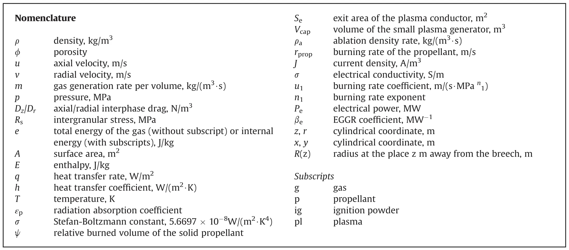
In this paper, firing test using the 30 mm ETC gun with DRPG was held.An axisymmetric two-dimensional interior ballistics model of the solid propellant ETC gun(2D-IB-SPETCG)is used to simulate the 30 mm ETC launch.The 2D-IB-SPETCG model includes:pulse forming network(PFN)discharge model[2,3], DRPG model and 2D two-phase flow model.Compared with the measured pressure and projectile muzzle velocity,the accuracy of the 2D-IB-SPETCG model is proved.Depending on the simulation results,the distribution of the propellant surface temperature,gas temperature,density and pressure during the ignition process are shown.The ignition process of the ETC launch is analyzed.
2.Physical model
Interior ballistics involves flow field components of a continuous(gas)and a discrete(solid propellant)nature.We consider that a single solid propellant is surrounded by the flow of the gas,so the solid propellant is considered to be pseudo fluid.On a suf ficiently small scale of resolution in both space and time,the components of the flow are represented by the balance equations for a multicomponent mixture describing the conservation of mass,momentum and energy.These equations require a number of constitutive laws for closure[23],including interphase drag,state equation,intergranular stresses,interphase transfer of energy and so on.All parameters are the function of time,axial and radial distance.
The multiphase governing equations,model of DRPG,transient burning rate law and numerical method are described in the following sections.
2.1.Multiphase governing equations
The balance equations for mass(gas or solid propellant)are given by
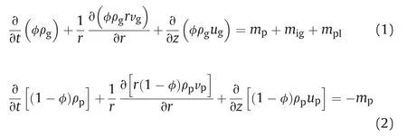
whereρgis the density of the gas,φis the porosity,ugis the axial velocity of the gas,vgis the radial velocity of the gas,mpis the gas generation rate of the solid propellant per volume,migis the gas generation rate of the ignition powder per volume,mplis the mass rate of the plasma per volume,ρpis the density of the solid propellant,upis the axial velocity of the solid propellant,andvpis the radial velocity of the solid propellant.
The balances of momentum for the gas and solid propellant take the form
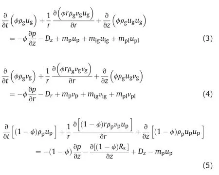

wherepis the pressure,Dzis the axial interphase drag,uigis the axial velocity of the ignition powder,uplis the axial velocity of the plasma,Dris the radial interphase drag,vigis the radial velocity of the ignition powder,vplis the radial velocity of the plasma,andRsis the intergranular stress.
The energy equation for the gas takes the form, and propellant in the chamber.The exit area decreases with the increasingof the porosityof the propellant.The plasma in the DRPG is deeply in fluenced by the environment in the chamber.It is considered that“ flowback”high pressure gas may lead to the current interruption of the DRPG.
In order to simulate the parameters in the DRPG,the working process can be simpli fied into two stages.At the beginning of the ignition,the pressure of the plasma is much higher than that in the chamber.Then the plasma diffuses in the chamber and the solid propellant is ignited.The in fluence of the environment in the chamber can be neglected.It is regarded as the“ flowout”stage which is quite similar to the CPG working process.With the combustion of the solid propellant,the gas pressure increases and the diffusion of the plasma is hindered.When the gas pressure is high

whereeis the total energy of the gas,e=eg+(ug2+vg2)/2,egis the internal energy of the gas,Apis the surface area of the solid propellant per volume,qcvis the convention heat transfer rate (qcv=hcv(Tg-Tp),hcvis the convention heat transfer coef ficient,Tgis the gas temperature,Tpis the surface temperature of the propellant),qradis the radiation heat transfer rate(qrad=εpσ(Tg4-Tp4),εpis the radiation absorption coef ficient,σis the Stefan-Boltzmann constant),Epis the enthalpy of the solid propellant,Eigis the enthalpy of the ignition powder,Eplis the enthalpy of the plasma.
The gas generation rate of the solid propellant per volume,mp,is given in the following form

whereψis the relative burned volume of the solid propellant.
2.2.Model of discharge rode plasma generator
The structure diagram of the DRPG is shown in Fig.1.The DRPG is consisted of a periodic array of solid(copper)and plasma (polyethylene)conductors.The DRPG can be considered as a couple of series plasma generators.The DRPG inserted into the chamber is surrounded by the solid propellant.The space inside the CPG makes it possible for the generation and flow of the quasi-stable plasma. While the radial exits for the plasma are free for the flow of the gas enough,the gas in the chamber begins to flow back into the DRPG. It is regarded as the“ flowback”stage.It makes the equivalent resistance of the DRPG increase rapidly.Finally,the current interruption occurs.
The DRPG is considered to be connected in series by small plasma generators with a couple of solid and plasma conductor. Depending on the model of CPG,the zero-dimensional(0D)model of the small plasma generator is built.The conservations of mass, momentum and energy during the“ flowout”stage are given by
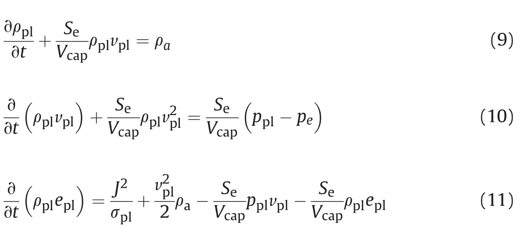
whereρplis the average density of the plasma,Seis the exit area,Vcapis the volume of the small plasma generator,ρais the mass ablation density rate,pplis the average pressure of the plasma,peis the gas pressure at the exit,eplis the speci fic internal energy of the plasma,Jis the current density,σplis the electrical conductivity of the plasma.

Fig.1.The structure diagram of the DRPG.
Duringthe “ flowback”stage,thein fluenceofthesolidpropellant is neglected.Only the gas in the chamber flows back into the DRPG and the“ flowback”gas mixes with the plasma which makes the equivalent resistance increase.The conservations of mass,momentum and energy are now changed to
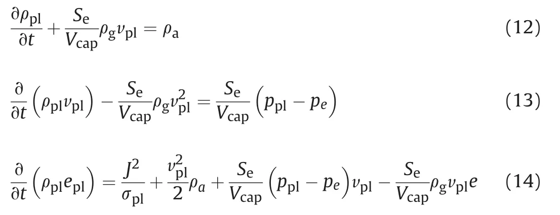
wherevpl<0,during the“ flowback”stage.
2.3.Transient burning rate law
A semi-empirical equation of propellant burning rate,including the in fluence of pressure gradient(dp/dt)and EGGR coef ficient by electric power,is presented[18,19].

whereu1is the burning rate coef ficient of the solid propellant,n1is the burning rate exponent,α(t)is time variable function of pressure and flame structure,Peis the electric power,βeis the enhanced gas generation rate(EGGR)coef ficient.
2.4.Numerical method
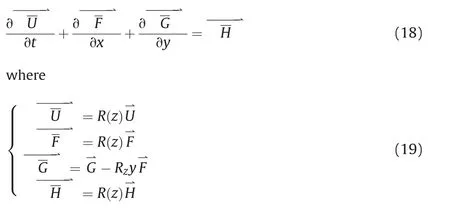
The multiphase governing equations(equations(1)-(7))can be transferred into the vector form for the calculation.The vector form of the conservation equations is given by

Fig.2 is the structure diagram of the computational domain in chamber.Because the cross section of the chamber varies with the z direction,the cross section of the computational domain is variable. In order to change variable cross section into uniform cross section, the following formula is used.

whereR(z)is the distance from the center axis to the wall while the axial distance from the breech iszm.
The uniform cross section computational domain is shown in Fig.3.And MacCormack scheme[24]with second-order accuracy is used to solve the vector.The vector form is transferred to
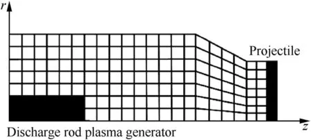
Fig.2.The structure diagram of the computational domain.
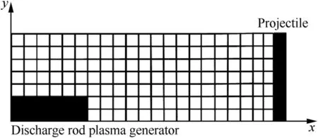
Fig.3.The structure diagram of the uniform cross section computational domain.
3.Results of the experiment and simulation
Fig.4 is the structure diagram of the 30 mm ETC gun with the DRPG and PFN.The PFN contains four modules which can be used independently as a system circuit.Each module contains a 1220μF capacitor,a 40μH inductance,a high power switch,a crowbar circuit and a surge protection resistor.Two modules are used and the discharge voltage is 10 kV.The standard projectile of 72 g was fired with 4/7 high-nitrogen propellant of 230 g in the experiment. The 4/7 high-nitrogen propellant is a homogeneous single-base propellant mainly containing nitrocellulose.The initial parametersofthe electrothermal-chemicallaunch are shown in Table 1(Tbis the ignition temperature of the propellant).A Kistler 6215 pressure transducer is added at the chamber wall,which is 0.13 m away from the breech.Velocity measuring screens are used to measure the projectile velocity.
The pressure of the experiment and simulation is shown in Fig.5.The peak pressure is 434 MPa in the experiment and 429 MPa in the simulation.The mean square error between the simulated and measured pressure is 27.3 MPa.The simulated muzzle velocity of the projectile[25]is 2085 m/s,while the experimental result is 2083 m/s.The relative error of the muzzle velocity is 0.1%.The accuracy of the 2D two-phase flow model is proved.
Fig.6 shows the measured and simulated current curve of the DRPG.At the beginning of the ignition,the simulated current accord well with the experimental current curve.The in fluence of the environment in the chamber on the DRPG increases with the increasing gas pressure.When the pressure is high enough,the stage of the DRPG is changed between the“ flowout”stage and the“ flowback”stage.The accuracy of the DRPG model decreases.
With the help of the 2D-IB-SPETCG model,the ignition process of the 30 mm ETC launcher can be analyzed.The distribution of the propellant's surface temperature during the ignition process is shown in Fig.7.At 0.04 ms,plasma begins to flow into the chamber. Because of the radial flowing plasma,the propellant in the area of the DRPG(the black area in Fig.7)is ignited within 0.01 ms (Fig.7(a)-(c)).With the spread of the gas,the propellant in thechamber is ignited within 0.09 ms.With the spread of the plasma, the gas temperature increases from several hundred K to several ten thousand K.The surface temperature of the propellant increases rapidly.And the ignition delay time decreases.Because of the DRPG,the radial ignition delay time is much less than the axial delay time[26].
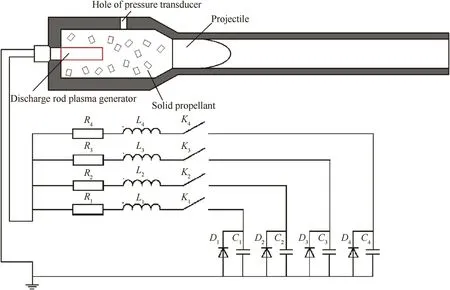
Fig.4.Structure diagram of the 30 mm ETC gun with DRPG.
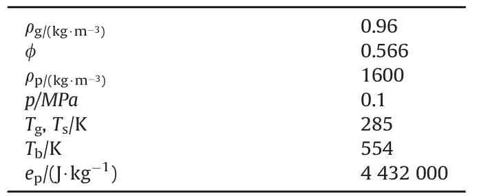
Table 1 The initial parameters of the electrothermal-chemical launch.
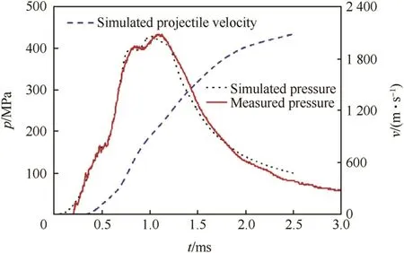
Fig.5.The measured and simulated pressure curve.
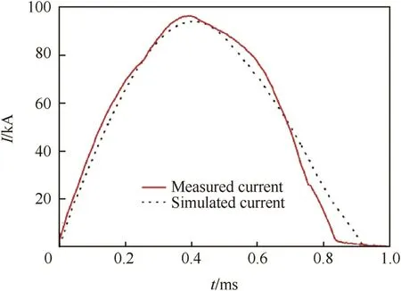
Fig.6.The measured and simulated current curve of the DRPG.
Fig.8 shows the gas pressure distribution from 0.04 ms to 0.12 ms.At 0.04 ms,the pressure near the axial center increases with plasma.Form Fig.7,we know that the propellant in the area of the DRPG is ignited in 0.1 ms(t≤0.05 ms).At the beginning of the ignition,the in fluence of the generation of the gas can be ignored. So the pressure changes with the flow of the plasma.With the diffusion of the plasma,the radial pressure increases rapidly and the high pressure moves from the center tothe wall.At 0.05 ms,the pressure near thewall is higher than that near the DRPG.Because of the burning of the propellant and the spread of the plasma,the pressure in the area of the DPRG increases rapidly,and the pressure of the area with the DRPG is much higher than the pressure of the other area(Fig.8(d)-(f)).Fig.9 shows the pressure difference between the place(X=0.025 m)near the DRPGand near thewall.The peak value of pressure difference is less than 5 MPa.At about 0.05 ms,the pressure difference achieves the minimum value(the same as Fig.8(c)).Owing to the“out flow”plasma,the pressure difference is positive(t>0.07 ms)during the ignition.The axial pressure difference makes the gas flow to the projectile.It makes the pressure at the end of the DRPG(X is 0.1 m)less than other place(X<0.1 m).When propellant in the chamber is nearly all ignited(at 0.12 ms)the pressure difference between the breech and the place near the projectile is less than 20 MPa.

Fig.7.The distribution of the propellant's surface temperature during the ignition process.
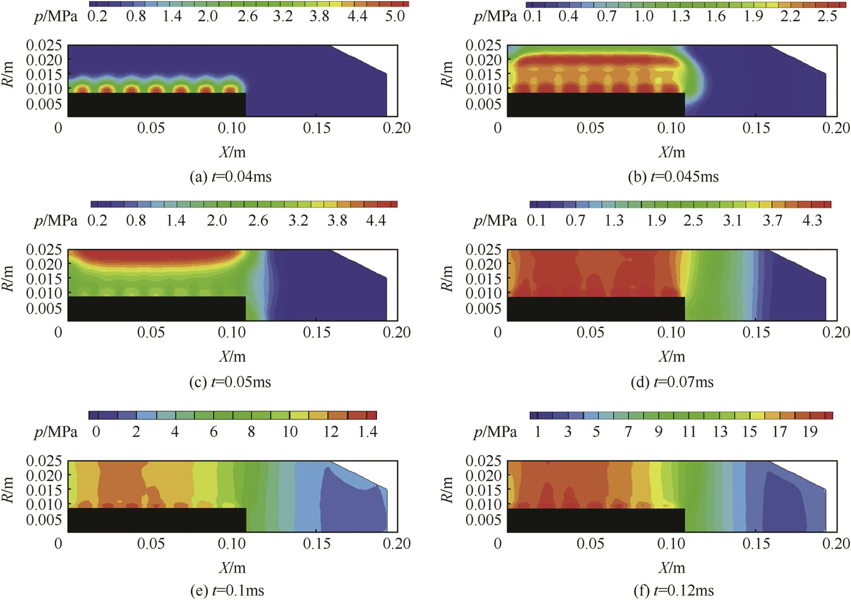
Fig.8.The distribution of the gas pressure.
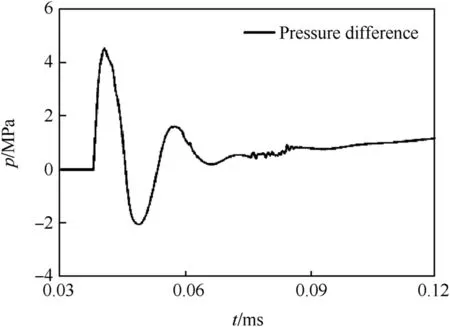
Fig.9.The axial pressure difference at the place 0.025 m away from the breech.
Fig.10 shows the gas temperature distribution from 0.04 ms to 0.12 ms.Due tothe spread of the plasma,the temperature of the gas increases from several thousand K(conventional ignition)to several ten thousand K[27].The generation of the gas increases the density of the gas and prevents the diffusion of the plasma[28].So the area of high gas temperature near the DRPG decreases with the combustion of the solid propellant.
The distribution of the gas density and the streamtraces from 0.04 ms to 0.12 ms are shown in Fig.11.From the streamtraces in Fig.11,we get the flow path of the gas.Because of the axial flowing plasma,the gas flows from the axial center to the wall.It makes the gas density at the wall and the axial center near the end of the DRPG higher than that at the other place from 0.05 ms to 0.07 ms. Due to the gas axial velocity,the gas flows fromthe end of the DRPG to the projectile and the high density area near the end of the DRPG disappears.The axial velocity of the gas at the breech is almost 0,it makes the gas stay near the breech and the density at the wall near the breech much higher than other place from 0.1 ms to 0.12 ms. Compared with the generated gas,the temperature of the plasma is much higher,while the density is much lower.From Figs.10 and 11, we know that the high density gas near the wall prevents the diffusion of the plasma and makes the plasma stay in the area near the DRPG.Low density and high temperature gas appears near the DRPG.The gas temperature may be higher than the plasma,owing to the internal energy and kinetic energy of the“ flowout”plasma.
4.Conclusions and further works
The 2D-IB-SPETCG model is developed to simulate the ETC launch with the DRPG.The accuracy of the model is proved by the experimental results of the 30 mm ETC launch.The working process of the DRPG is simpli fied into two stages,the“ flowout”stage and“ flowback”stage.The current interruption occurs,because of the“ flowback”gas.More works can be done to improve the accuracy of the DRPG model,such as the Lorentz force and the characteristics of the“ flowback”gas.
According to the simulated results,the ignition process of the 30 mm ETC launch is analyzed.The ignition delay time with the plasma reduces to 0.08 ms.Because of the DRPG,the radial ignition delay reduces to 0.01 ms.During the ignition process,the radial pressure difference is less than 5 MPa at the place 0.025 m away from the breech.It proves that the DRPG can improve the radial ignition consistency.The temperature of the gas increases from several thousand K(conventional ignition)to several ten thousand K(plasma ignition).Low density and high temperature gas appears near the exits of the DRPG,while high density and low temperature gas appears at the wall near the breech.More computational methods should be added into the model in the future to improve the accuracy of the simulation.
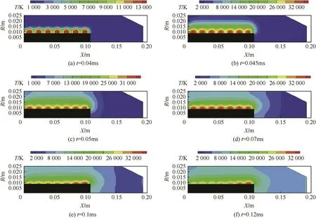
Fig.10.The distribution of the gas temperature.
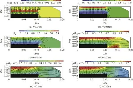
Fig.11.The distribution of the gas density.
[1]Sha fir N,Zoler D,Wald S,Shapira M.Reliable,highly reproducible plasma injectors for electrothermal and electrothermal-chemical launchers.IEEE Trans Magn 2005;41(1):355-9.
[2]Lee YH,Park KJ,Jung JW.Load resistance estimation in ETC experiments.IEEE Trans Magn 2002;39(1):248-52.
[3]Jin Y,Zhang YZ,Li ZX,Li BM.Primary analysis of pulse forming network discharge with time-varying resistance.High Volt Eng 2014;40(4):1121-6.
[4]Hewkin D,Figura E.Fundamental research and numerical modeling of the internalballisticsofelectrothermalchemicalguns.IEEE TransMagn 1993;29(1):561-6.
[5]Kim K.Numerical simulation of capillary plasma flow generated by highcurrent pulsed power.Int J Therm Sci 2005;44:1039-46.
[6]Winfrey AL,Al-Halim MAA,Gilligan JG,Saveliev AV,Bourham MA.A study of plasma parameters in a capillary discharge with calculations using ideal and nonideal plasma models for comparison with experiment.IEEE Trans Plasma Sci 2012;40(3):843-52.
[7]Powell JD,Thornhill LD.Current distribution and plasma properties in injectors for electrothermal-chemical launch.IEEE Trans Magn 2001;37(1): 183-7.
[8]Powell JD,Thornhill LD,Batteh JH,Verdon M.Current distribution and resistance characteristics in plasma injectors for electrothermal-chemical launch. IEEE Trans Magn 1999;35(1):218-23.
[9]Kaste P,Birk A,Kinkennon A,Lieb R,Del Guercio M,Schroeder M,et al. Analysis of burning rate phenomena and extinguished solid propellants from an interrupted closed bomb with plasma igniter.IEEE Trans Magn 2001;37(1): 173-7.
[10]Brik A,Del Guercio M,Kinkennon A,Kooker DE,Kaste P.Interrupted-burning tests of plasma-ignited JA2 and M30 grains in a closed chamber.Propell Explos Pyrot 2000;25(3):133-42.
[11]Aberg D,Svanberg LP,Olsson FETC.40-mm gun firings in the low-inputenergy regime.IEEE Trans Plasma Sci 2011;39(1):374-7.
[12]Alimi R,Borenstein A,Goldenberg C,Perelmutter L,Pokryvailo A,Sha fir N, et al.ETC research at Soreq NRC.Isr IEEE Trans Magn 2001;37(1):11-5.
[13]Dyvik J,Herbig J,Appleton R,O'Reilly J,Shin J.Recent activities in electrothermal chemical launcher technologies at BAE system.IEEE Trans Magn 2007;43(1):303-7.
[14]Porwitzky AJ,Keidar M,Boyd ID.Modeling of the plasma-propellant interaction.IEEE Trans Magn 2007;43(1):313-7.
[15]Jin Y,Li BM.Energy skin effect of propellant particles in electrothermalchemical launcher.IEEE Trans Plasma Sci 2013;41(5):1112-6.
[16]Woodley CR,Billett SJ.Modeling enhanced gas generation rates in a 155-mm ETC gun.IEEE Trans Magn 2001;37(1):207-10.
[17]Grune D,Hensel D.Combustion behavior of LOVA-solid-propellant by ignition with hot plasma gases and its in fluence on the interior ballistic cycle.In:17th international symposium on ballistics,vol.1;1998.p.359-66.
[18]Ni YJ,Xing RJ,Wan G,Jin Y,Li HY,Yang CX,et al.Porous propellant burning rate enhanced by plasma.Explos Shock Waves 2016;36(4):562-7.
[19]Ni YJ,Jin Y,Wan G,Yang CX,Li HY,Li BM.Application of transient burning rate model of solid propellant in electrothermal-chemical launch simulation.Def Technol 2016;12(2):81-5.
[20]Wald S,Alimi R,Bakshi L,Falkovitz J,Pokryvailo A,Ravid A,et al.Electrothermal-chemical research at Soreq nuclear research center,Israel.IEEE Trans Magn 2005;41(1):165-70.
[21]Ni YJ,Cheng NK,Jin Y,Yang CX,Li HY,Li BM.Numerical simulation on pressure wave in a 30 mm electrothermal-chemical gun.Acta Armamentarii 2016;37(9):1578-84.
[22]Porwitzky AJ,Keidar M,Boyd ID.Progress towards an end-to-end model of an electrothermal chemical gun.IEEE Trans Magn 2009;45(1):412-6.
[23]Weng CS,Wang H.Computional interior ballistics.Beijing:National Defence Industry Press;2006.p.71-6.
[24]MacCormark RW.The effect of viscosity in hypervelocity impact cratering[R]. 1969.p.1969-2354.
[25]Carlucci DE,Jacobson SS.Ballistics:theory and design of guns and ammunition.CRC Press;2007.
[26]Wald S,Alimi R,Bakshi L,Falkovitz J,Pokryvailo A,Ravid A,et al.ETC research at Soreq NRC,Israel.In:12th symposium on electromagnetic launch technology;2004.p.21-6.
[27]Chang LM,Howard SL.Electrothermal-chemical plasma ignition of gunpropelling charges:the effect of pulse length.Aberdeen Proving Ground, MD:Army Research Laboratory;September 2007.ARL-TR-4253.
[28]Alimi R,Perelmutter L,Onn U.Modeling an internal injection process for the solid propellant electrothermal-chemical gun.In:16th international symposium on ballistics;1996.p.409-18.
18 January 2017
*Corresponding author.
E-mail addresses:chelseatal@163.com(Y.-j.Ni),li_haiyuan@163.com(H.-y.Li).
Peer review under responsibility of China Ordnance Society.
http://dx.doi.org/10.1016/j.dt.2017.05.004
2214-9147/©2017 The Authors.Published by Elsevier Ltd.This is an open access article under the CC BY-NC-ND license(http://creativecommons.org/licenses/by-nc-nd/4.0/).
in revised form
- Defence Technology的其它文章
- The uncertainty propagation analysis of the projectile-barrel coupling problem
- Studies on composite solid propellant with tri-modal ammonium perchlorate containing an ultra fine fraction
- Study on the effect of RDX content on the properties of nitramine propellant
- The in fluence of nozzle diameters on the interaction characteristic of combustion-gas jets and liquid
- Electrostaticspray preparation and properties of RDX/DOS composites
- Projected area and drag coef ficient of high velocity irregular fragments that rotate or tumble

