Validation of the NATO Armaments Ballistic Kernel for use in small-arms fire control systems
D.Corriveau
Defence R&D Canada,2459 De La Bravoure Rd.,Quebec QC G3J 1X5,Canada
Validation of the NATO Armaments Ballistic Kernel for use in small-arms fire control systems
D.Corriveau*
Defence R&D Canada,2459 De La Bravoure Rd.,Quebec QC G3J 1X5,Canada
A R T I C L E I N F O
Article history:
Aerodynamics
Ballistics
Trajectory
BALCO
NABK
Ballistic computer
Sniper system
In support for the development of a new small-arm ballistic computer based on the NATO Armaments Ballistic Kernel(NABK)for the Canadian snipers,DRDC Valcartier Research Centre was asked to carry out high-fidelity 6 degree-of-freedom(6-DOF)trajectory simulations for a set of relevant vignettes for the snipers,and to compare the direct fire 6-DOF simulation results with those obtained with the 4-DOF NATO Armaments Ballistic Kernel(NABK)adapted to simulate small-arm ammunition trajectories.To conduct this study,DRDC Valcartier Research Centre used BALCO v1.0b.This paper presents(1)the process and the methodology employed to carry out the sniper direct fire solution study,(2)the modeling and the simulation of the sniper projectile,the approach used in calculating the firing solutions,and the results of direct fire simulations for the sniper vignettes,and(3)an analysis of firing solutions obtained with the BALCO engine versus those of NABK.The work presented in this paper serves to validate the use of NABK for the new sniper ballistic computer.
Crown Copyright©2017 Published by Elsevier Ltd.This is an open access article under the CC BY-NC-ND license(http://creativecommons.org/licenses/by-nc-nd/4.0/).
1.Introduction
The development of the NABK started in the nineties in what is now called the NATO Land Capability Group 3 Sub-Group 2. Members of this group elected for a standard,generic,and layered set of software modules for ballistic processing[1].The Ada computer language was selected given its wide acceptance and embedded application capability.The NABK was first released in 1995 for use in artillery and mortar technical fire control applications.It is currently used by more than ten NATO countries as the main ballistic engine for the artillery and mortar applications.The NABK is also planned for use by navalapplications as wellas in the next generation of fire support systems including guided artillery, mortars and direct fire applications such as fighting vehicles and tanks.
Although the NABK has been a very successful ballistic engine for various types of weapon systems and for the development of firing tables[2][3],the small arms fire control for individual and crew served weapons ballistic solution is one area where the NABK is not well suited due to the unique requirements of the domain. Historically,fire controlsystems for smallarms presented a unique environment and requirements to the developer of technical fire controlsystems.Smallarms fire controlsystems are typically small in size which limited the available computer resources;CPUs are of lower power with correspondingly less processing capabilities;the amount of random access memory may also be limited.Operating systems used in small arms fire control systems are typically embedded real-time systems.This limits the choice of computer programming languages and compilers that support these systems and also places real-time requirements on the applications thatrun under the hardware and operating system.However,with the constant miniaturization of electronic components and the continually increasing computer power,the factors preventing the use of the NABK for small-arms fire control system have progressively been eliminated.
With today's smartphone platform,it was demonstrated by the Canadian snipers that the computer power of these devices was suf ficientto run the NABK and instantly generate a ballistic solution for the snipers.Fig.1 shows the Canadian snipers NABK ballistic computer kit with the various sensor connectors and power pack.
In this paper,the work performed to validate the use of NABK as a ballistic engine for the Canadian snipers ballistic computer is presented.Comparisons between the trajectory predicted by NABK and BALCO are presented for a typical 7.62 mm sniper projectile.Various engagement scenarios are investigated to con firm that NABK performs well for different environmental conditions and firing directions.The comparison of the results obtained from the two ballistic engines are made and discussed.
2.NABK in brief
The NATO Armament Ballistic Kernelis a 4-DOF modi fied point mass model.This is a compromise between a simple point mass model and a computationally intensive 6-DOF model.NABK is based on the mathematical model de fined by the NATO STANAG 4355[4]:The Modi fied Point Mass and Point Mass Equations of Motion.In the modi fied point mass model,the effects due to the spin rate ofa projectile are included contrary to a simple pointmass model.Thus,the equilibrium yaw angle in both the lateral and trajectory plane is taken into accountfor calculation ofthe driftand drag.The 4-DOF modi fied point mass model is the algorithm implemented in trajectory simulation programs NABK.The trajectory integration is carried out using the Runge-Kutta-Fehlberg integration scheme.This is a fourth order numerical integration scheme.The projectile and the environment can be described with various levels of detailusing the following models:
·Earth:flat(fixed gravity),spherical(STANAG 4355)or ellipsoidal (WGS84)Earth model;
·Atmosphere:standard atmosphere(ISO 2533-1975)or userde fined atmosphere,including a 1D or 3D wind field;
·Aerodynamics:axisymmetric projectiles,isolated control surfaces,aerodynamic coef ficients described by polynomials;
·Inertia data:symmetric matrix of inertia;
·Base-burn and rocket assistance models(STANAG 4355);
·5-DoF for fin stabilized rocket
3.BALCO in brief
BALCO is a 6/7-DoF trajectory simulation program based on the mathematical model de fined by the NATO Standardization Recommendation 4618[5][6].The primary goal of BALCO is to compute high-fidelity trajectories for both conventional and precision-guided projectiles.The 6-DoF model is used to describe the motion of single rigid bodies.The 7-DoF model allows the description ofa projectile which consists oftwo coaxialrigid bodies that can spin independently.Actuators such as isolated control surfaces(e.g.fins or canards),thrusters or internal rollcontrol devices can optionally be attached to the rigid body.Controlling the state of these actuators offers a controlauthority on the trajectory. The 6/7-DoF equations of motion can be expressed in three differentframes,namely,body-fixed,zero rolland zero spin frames, depending on the contextofthe study.The trajectory integration is carried out using an accurate seventh-order Runge-Kutta scheme. The projectile,the environment and the optional guidance,navigation and controlcapabilities can be described with various levels of detailusing the following models:
·Earth:flat(fixed gravity),spherical(STANAG 4355)or ellipsoidal (WGS84)Earth model;
·Atmosphere:standard atmosphere(ISO 2533-1975)or userde fined atmosphere,including a 1D or 3D wind field;
·Aerodynamics:axisymmetric or non-axisymmetric projectiles, isolated controlsurfaces,aerodynamic coef ficients described by multidimensional look-up tables or polynomials;
·Inertia data:symmetric or asymmetric matrix of inertia,userde fined timedependent inertia;
·Thrusters:user-de fined time-dependent 3D vector thrusts;
·Base-burn and rocket assistance models(STANAG 4355);
·Embedded actuators(open-or closed-loop flight control):isolated controlsurfaces,thrusters and internalrolling moment for dual-spin bodies;
·Guidance,navigation and control models implemented as external functions using a common communication interface (closed-loop flight control).
4.Sniper ammunition model
The sniper ammunition of used for this project is the NATO 7.62×51 mm,OTBT(Open Tip Boat Tail),168 gr,Match,which is simply referred to in this paper as the C175.The aerodynamic model for this round was developed using PRODAS(Fig.2)combined with some experimental firing radar traces.
The aerodynamic coef ficients generated in PRODAS that are actualinputs to the BALCO modeland NABK modelare as follows: CD0,CD2,CD4,CLα0,CLα3,CMα,C Mq,C lp,C Nq,C Ypαand C M pα.
The coef ficients CD0,CD2and CD4are used to calculate to total drag coef ficient taking into account the projectile's yaw as follows
whereδ=sinαt.αtis the totalangle of attack.
The lift force coef ficient CLαis often nonlinear as the yaw level varies.This behaviour is captured using the following relationship
The pitching moment is directly related to the lift force.For small caliber projectiles,the pitching moment is usually positive. Therefore,ifthe nose ofthe projectile rises above the trajectory,the pitching momentwillactas to increase the yaw angle.The pitching moment relates to the pitching moment coef ficient as follows
The pitch damping moment arises from the attenuation of pitching motion of a projectile due to the air resistance.The pitch damping moment relates to the pitch damping moment coef ficient as follows:
where qtis the totalangular velocity.
Similarly,the pitch damping force relates to the pitch damping force coef ficient as follows
The spin damping moment opposes the spin of the projectile.It relates to the spin damping coef ficient as follows
The Magnus force arises fromthe unequalpressures distribution on either side of a spinning body.This is the result of the viscous interaction between the spinning projectile body and the fluid.The Magnus force relates to the Magnus force coef ficient as follows
Similarly,the Magnus moment is a function of the Magnus moment coef ficient given as
5.Direct fire simulation comparison study
In order to compare the direct fire solution of NABK with that obtained from the 6-DOF trajectory simulation code BALCO a set of 20 vignettes was developed.These vignettes represent typical firing conditions that could be encountered around the world by the snipers.The vignette locations are shown in the map presented in Fig.3.
The vignettes spread locations all over the world,as shown as squares on the simple map of Fig.3.The vignettes also cover a relatively large range ofair temperatures(from-40°C to 49°C),air pressure(from 98.1 kPa to 103.6 kPa),relative humidity(from 0 to 100%),wind speed(from 0 to 30 km/h),gun altitude(from 0 to 3600 m),gun range(from 300 to 1200 m),angles of sight (from-533 to 355 mils),and propellant temperature(from-20°C to 70°C).The vignettes data are presented in Table 1 to Table 3.
A vignette is a simulation scenario composed of de fining elements.Typically,one finds the following parameters in a vignette: geo-location and altitude of the shooter,shooter-target range, altitude of target,temperature and barometric pressure at the shooter location,relative humidity at the shooter position,wind speed and direction,ri fle azimuth from the North,and shootertarget slant angle.
Simulation involves numerically running a model of the projectile,namely solving the equations of motion over time,preferably in the BALCO environment,under the conditions of interest, and then collecting the results,such as projectile position and velocity versus time,to cite a few.
Brie fly,the projectile modelis characterized by the usual aerodynamic parameters[7].The parameters are obtained with PRODAS,leveraging the knowledge of the geometry of the projectile. Furthermore,some radar traces were used to re fine the aerodynamic model.The PRODAS aerodynamic model is implemented in BALCO.The 6-DOF numericalsimulations are run in BALCO.The trajectory of the projectile is obtained through the solution of the equations of motion;namely,a solution to a number ofdifferential equations calculated with classical Runge-Kutta methods.

Table 1 Original vignettes 1 to 7.

Table 2 Originalvignettes 8 to 15.

Table 3 Original vignettes 16 to 20.
As a minimum the following results were collected on the ri fle and projectile:quadrant elevation(QE),super elevation(SE),time of flight,velocity at impact,transonic entry distance,maximum ordinate,azimuth of fire(with and without Coriolis effect,and with and without wind),and drift angle(due to projectile spin,Coriolis effect,and wind,and due to a combination of those factors).These parameters are de fined in the report and their values obtained for the various vignettes are presented.
The following elements are of particular importance for the sniper:super elevation,drift angle,and range to transonic entry. And as such,these variables are collected during the simulations.
6.Approach
The steps in the DRDC simulation study are shown in Fig.5.The six steps are carried out for each vignette.Then,results of the simulations are collected,metrics are calculated,and differences between NABK and BALCO are quanti fied and analysed.
Once the projectile data is entered for a vignette,the information is valid and fixed for all vignettes.The vignette speci fic information on geometry,meteorologicalconditions,wind parameters, and geo location are extracted from the Excel table,and entered into the BALCO input script file.Using the tabular data associated with a vignette,one fills out the BALCO input file as follows:
·$ISO_Atmosphere_Correction_Data is entered as the triplet altitude[m],temperature[K],and pressure[Pa],
·$Wind_Data is entered as components in a Cartesian frame, with one component along x1(down-range),followed by a component along x2(vertical,always zero here),and finally a component along x3(cross-range),
·$Longitude_Latitude_Azimuth is entered as longitude(deg)and latitude(deg),complying with the sign convention used in this study,and as azimuth(deg)of fire(speci fically,the azimuth from the North entry of the vignette table data),in this order,
·$Initial_Position is entered as down range(m)of zero,height (m)above sea level as given in the vignette table,and cross range(m)of zero,in this order,as the position of the shooter (gun).
Targetlocation is determined from the geometry ofthe vignette, using the vignette information on the slant angle,the height ofthe shooter,and the range to target.Actually,target height from sea levelis critical,as it serves in the evaluation ofthe drift angle.Fig.4 presents a generic geometry and basic calculations to obtain target height(y)from vignette parameters.
The next step pertains to setting the QE,the initial conditions, the stopping conditions,and the format of the simulation output. Obtaining the QE value,by trial and error,that results in the projectile hitting the target is the iterative part of the approach.Using the tabular data associated with a vignette:
·$Initial_Time is set to zero,
·$Initial_Velocity is entered as the triplet of magnitude(m/s)of the projectile at firing obtained from the NABK data,followed by the de flection angle set to zero,and the elevation angle(QE)as the estimated value to reach the target,
·$Initial_Angular_Position is entered as 0,0,and 0(for aerodynamic roll angle,total angle of attack,and roll angle),
·$Initial_Angular_Velocity is entered as the spin rate(rad/s)of the projectile obtained with PRODAS(with NABK supplied projectile velocity magnitude at firing),and followed by zero pitch rate,and zero yaw rate,
·Stopping condition is$Trajectory_Limit entered as the range to target value for the vignette,
·$Print_Time_Step is entered as the appropriate value that gives enough increment in the output,and may vary from 0.0005 s to 0.01 s depending on the vignette and output results.
With the aforementioned key parameter values identi fied and set,the simulations of a vignette may be run,as shown in Fig.5.
As for the trialand error process associated with the QE value,a simulation is first run with the originally guessed QE value.One obvious choice for the firstguess on QE is the NABK QE value,which is available.The projectile location obtained at the downrange target position is then compared with that expected from the geometry ofthe shooter-target,with a computation as shown in Fig.4. Ifthe projectile does notend up at the correct targetaltitude within 2 decimalplaces in units of meters,at the target downrange value location,the QE is set to another value,and the simulation is run again.The process is repeated untila satisfactory projectile altitude at target is obtained.
Note that several simulations are run for a given vignette and fixed(final)QE value to allow for post-processing calculations that isolate the effects of three variables on the drift angle:Coriolis effect,wind,and bullet spin.
7.Results
The results obtained with BALCO and NABK for the sniper vignettes are presented in Table 4 to Table 10.The variables used for performance evaluation and other variables,as required by the snipers,are shown in the tables.The columns are arranged such thatthe NABK and BALCO results are presented side by side for each vignette.
Other variables of interest found in the results tables are as follows:projectile's time of flight,muzzle velocity(MV),velocity at impact(actually,when projectile is closest to target),transonic entry distance,maximum ordinate,and range to maximum ordinate.Range to maximum ordinate is the distance from the gun position to the horizontal coordinate of the location of the projectile when it reaches its highest altitude.
8.NABK versus BALCO trajectory comparisons
The objective of the veri fication and validation process is to demonstrate the accuracy of NABK solution so that it may be used with con fidence in a ballistic computer for the snipers.According to AIAA guidelines[8],the veri fication process determines if the programming and computational implementation of the conceptual model is correct.It examines the mathematics in the model through comparison with exact analytical results and checks for computer programming errors.As for the validation process,it determines if the computational simulation agrees with physical reality through comparison with experimental results.
To compare the trajectory algorithms of NABK with that of BALCO,one may state a number ofobservations on the results using Table 11 to Table 14,in particular those tables featuring the differences in key variables.A detailed explanation of the results obtained with NABK is outside the scope of the analysis.
For each vignette,the difference in NABK and BALCOQE inputs is smaller than or equal to 0.012°.The maximum value of 0.012°is obtained with vignette 19.If one omits vignette 19,the largest difference in QE is smaller than or equalto 0.0098°.The same observations can be made for SE.
The maximum difference in magnitude of velocity at impact between NABK and BALCO for all vignettes is 2%.The maximum is obtained with vignette 19.If one discards this vignette,the maximum difference falls to 0.6%.
The relatively large difference in NABK and BALCO QE inputs observed for vignette 19 can be explained in terms of the virtualtemperature.NABK simulations rely on the virtual temperature, which takes into account the relative humidity in the air.For most vignettes,the difference between the air temperature and the virtual temperature was relatively small or non-existent,thereforehad a minor impact on performance of the projectile.However, with vignette 19,one has a scenario with a very high temperature and high levelofhumidity.For vignette 19,the virtualtemperature was 53.6 deg C as compared with 44 deg C for the air temperature.The temperature is used to calculate the flight Mach numbers which in turn are used to extract the aerodynamic coef ficients. Thus for large temperature differences,one expects signi ficant discrepancies in the aerodynamic coef ficients,such as the dragcoef ficient.Furthermore,the difference in temperature is expected to signi ficantly impact velocity at the target with a relatively large separation between the shooter and the target.With vignette 19, the range was relatively long at 800 m.This only exacerbated the difference in projectile performance as obtained with NABK and BALCO.
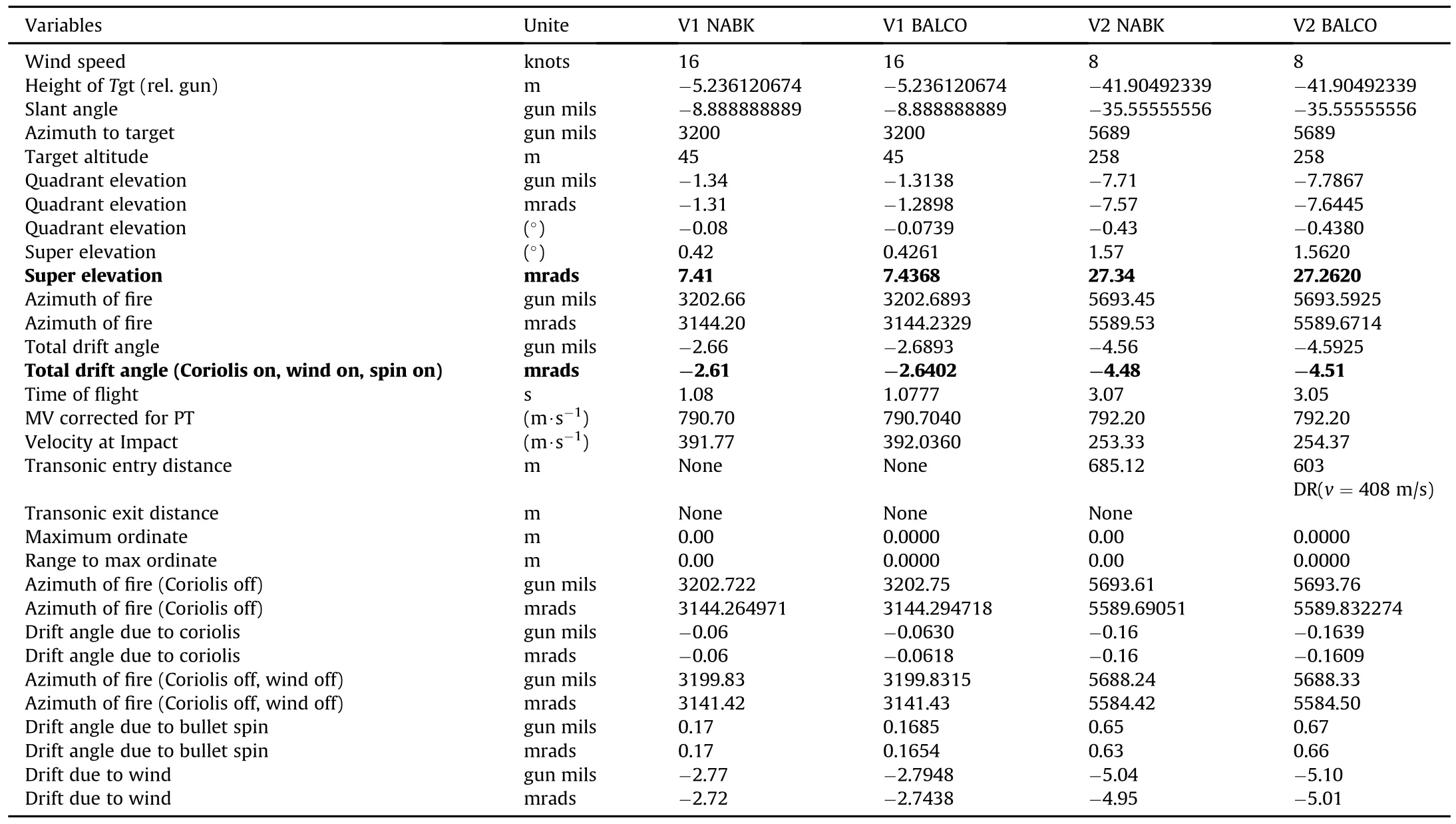
Table 4 Results for vignettes 1 and 2.
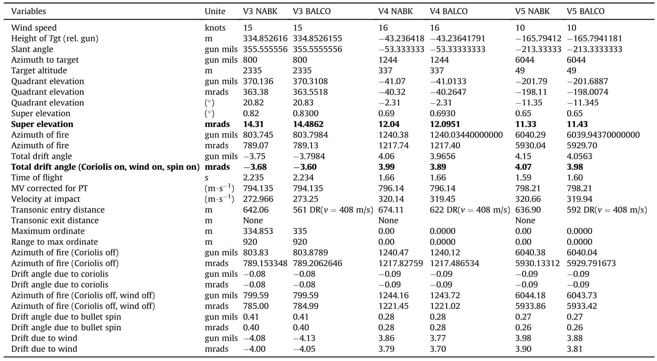
Table 5 Results for vignettes 3,4 and 5.
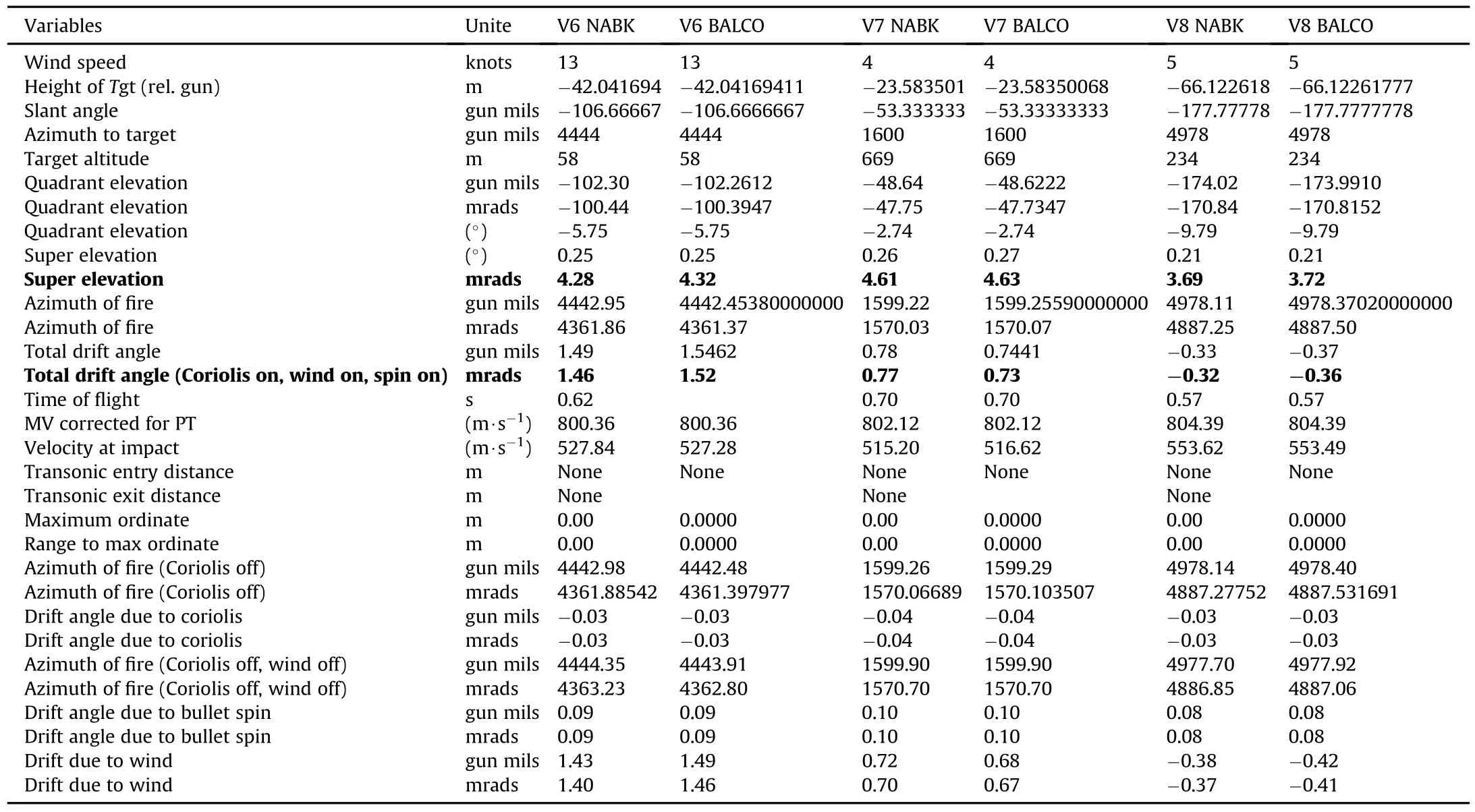
Table 6 Results for vignettes 6,7 and 8.
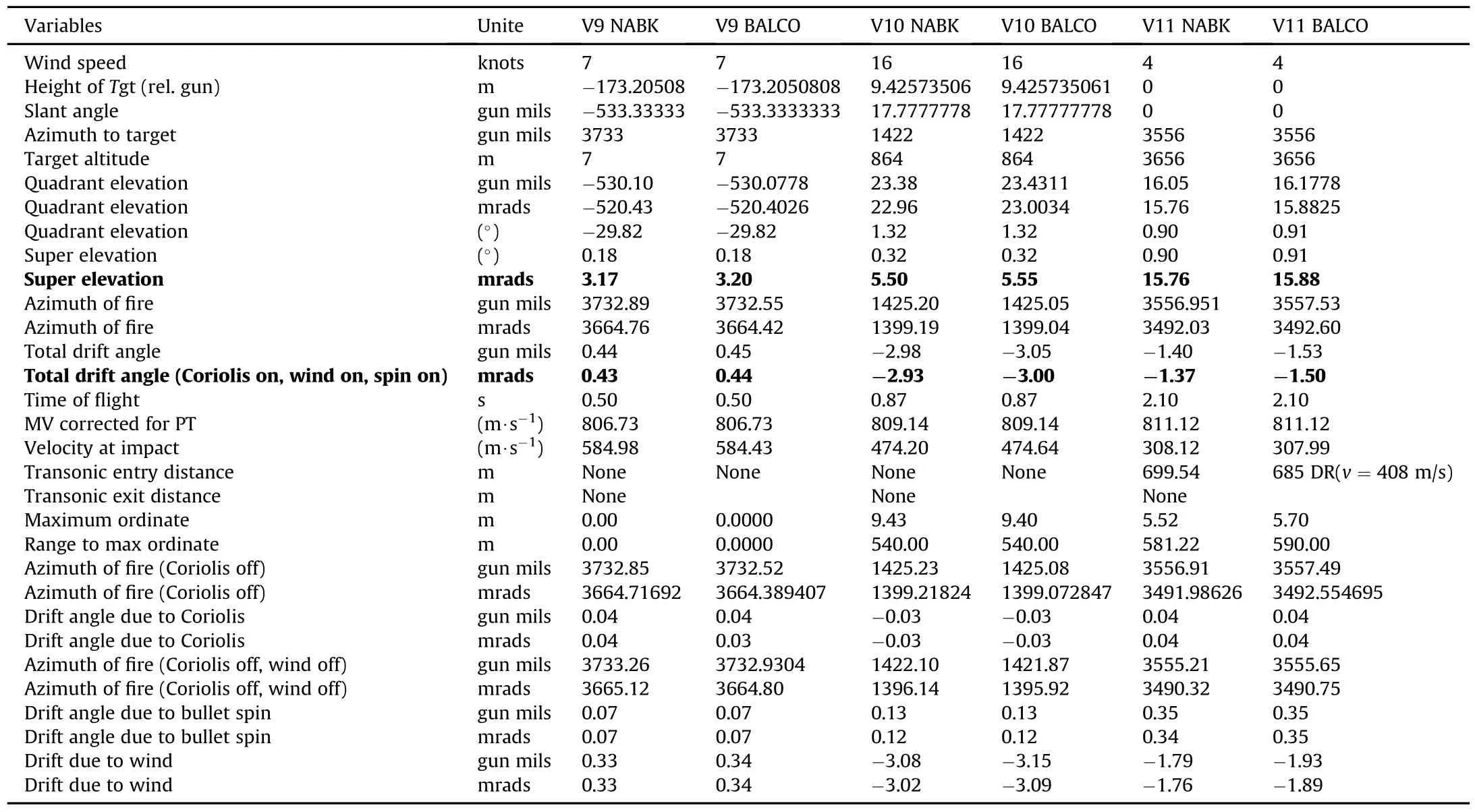
Table 7 Results for vignettes 9,10 and 11.
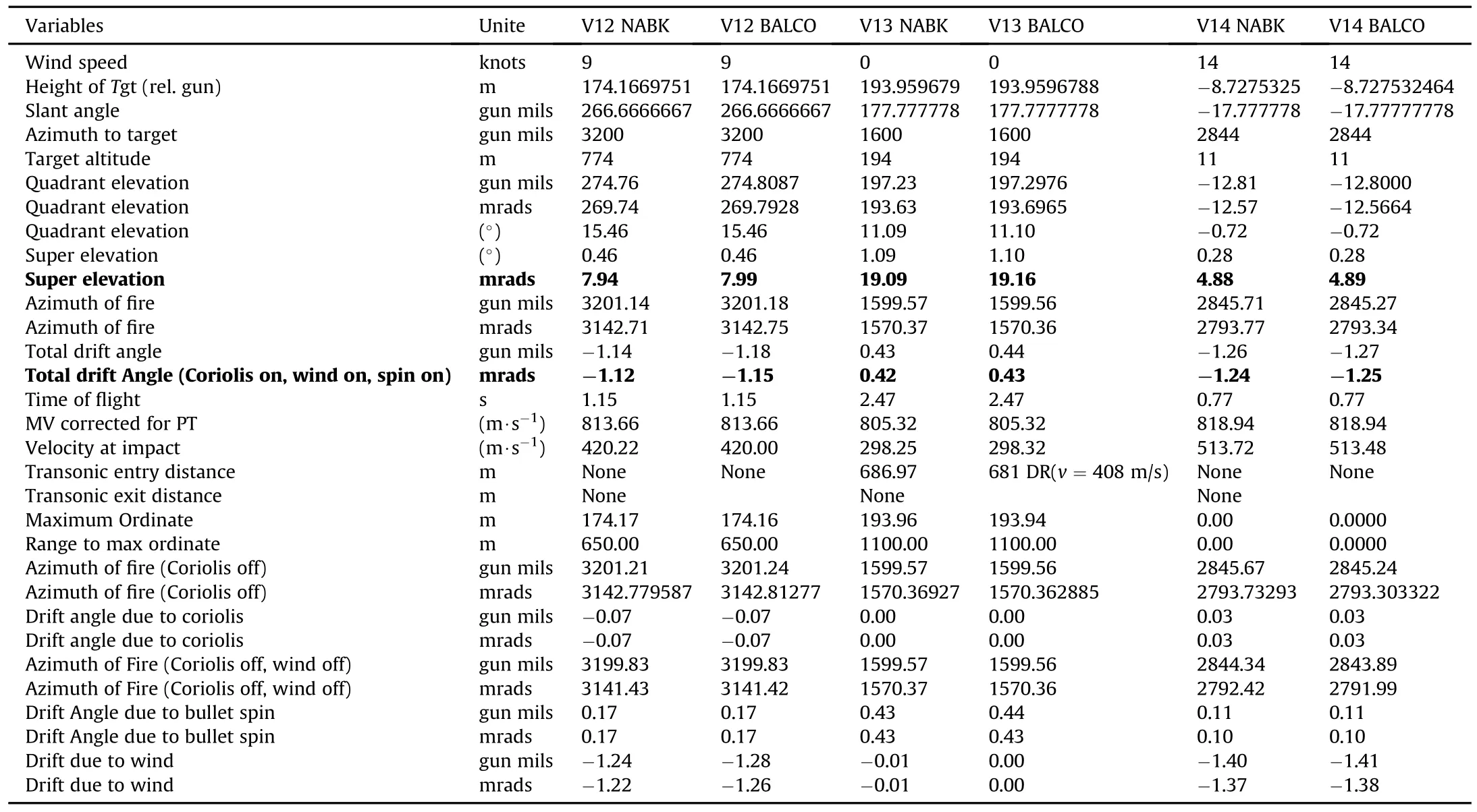
Table 8 Results for vignettes 12,13 and 14.

Table 9 Results for vignettes 15,16 and 17.
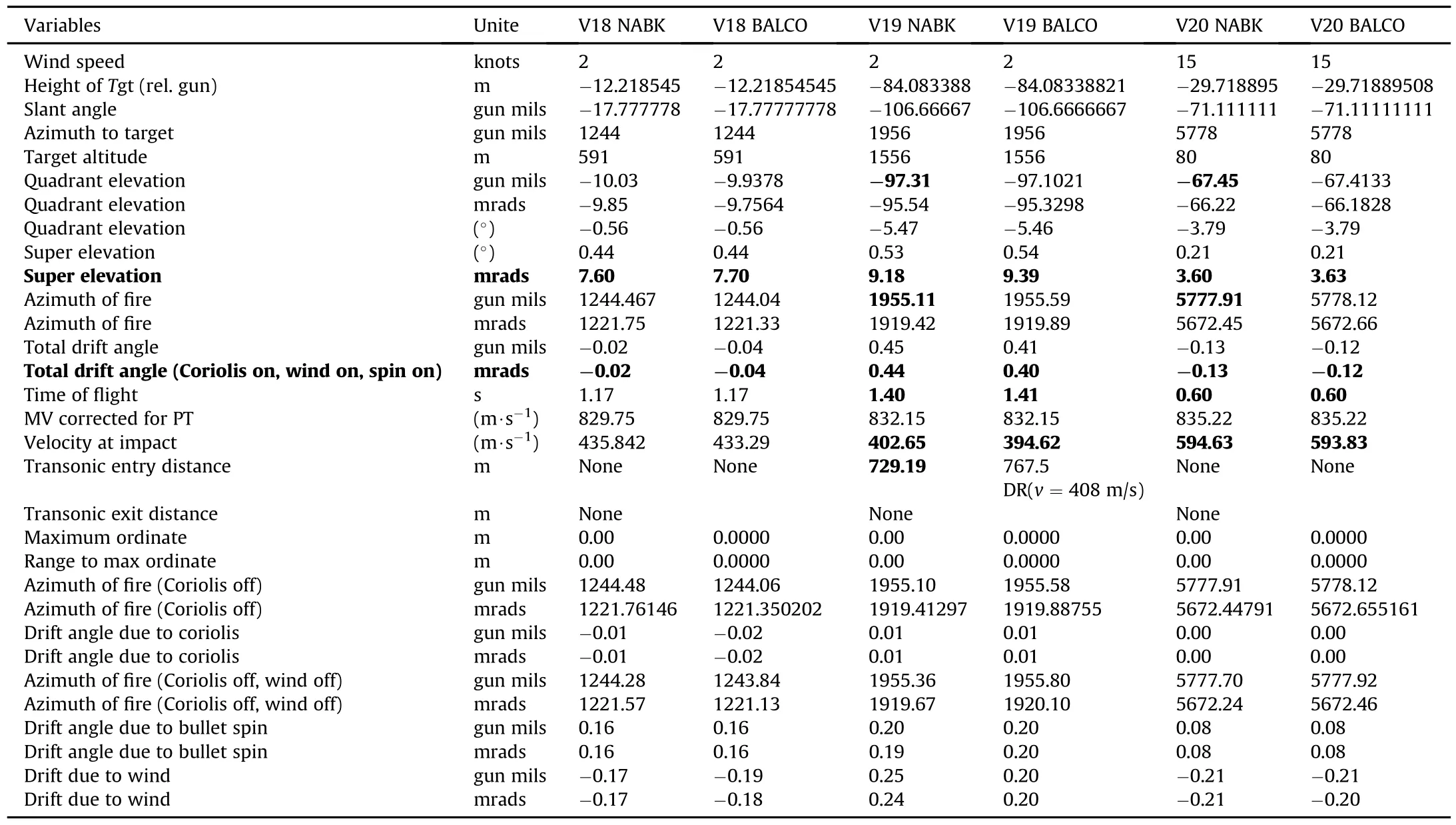
Table 10 Results for vignettes 18,19 and 20.
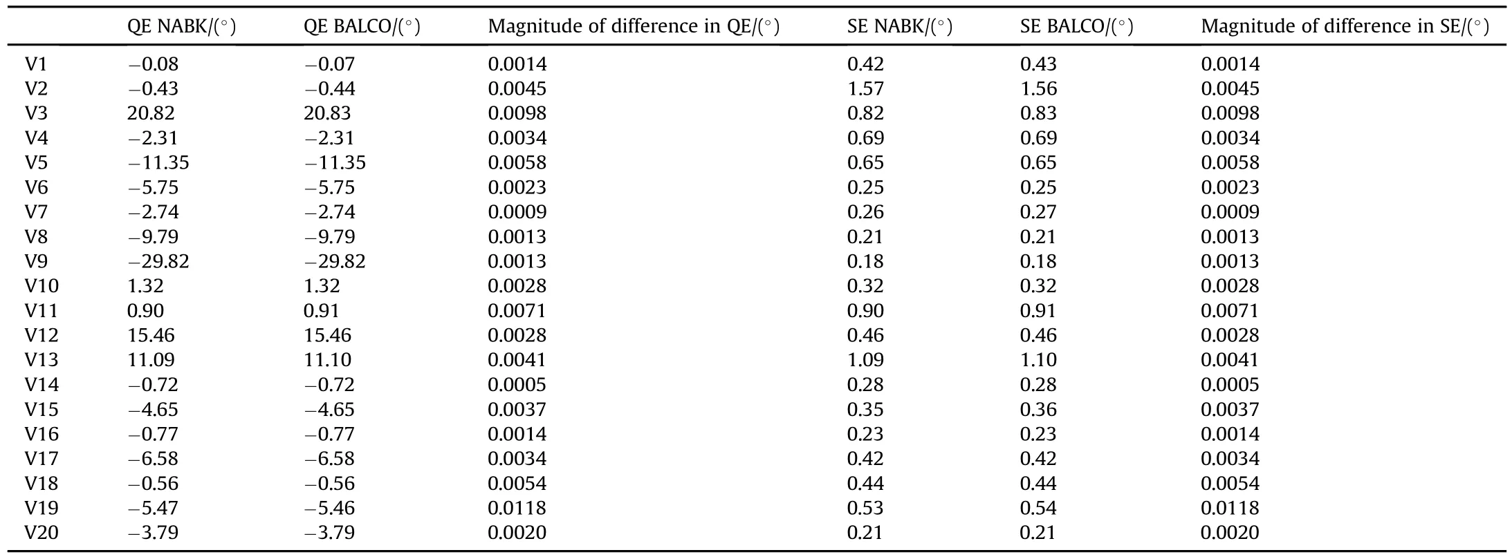
Table 11 NABK-BALCO differences in QE,SE.
The differences in total drift angles obtained with NABK and BALCO for all vignettes are shown in Table 13.The maximum difference is 0.13 mils,or 0.0073°,obtained with vignette 11,and the second largest is 0.09 mils,obtained with vignettes 4 and 5.The average NABK-BALCO difference in totaldrift angle is 0.04 mils.
In case of projectile drift due to Coriolis effects,wind and bullet spin,the results of the comparison between NABK and BALCO are presented in Table 14.Magnitude of the difference between drift due to Coriolis obtained with NABK and BALCO is the largest for vignette 18(rounded value of 0.009 mils).Magnitude of the difference between drift due to projectile spin obtained with NABK and BALCO is the largest for vignette 2(rounded value of 0.027 mils).Magnitude ofthe difference between driftdue to wind effects obtained with NABK and BALCO is the largest for vignette 11
(rounded value of 0.137 mils).The average difference NABK-BALCO in projectile drift due to Coriolis effects is 0.0012 mils,that due to projectile spin is 0.0034 mils,and that due to wind is 0.0422 mils (using rounded values for the calculation of the average).On average,wind has the largest impact on drift size among the three factors considered.
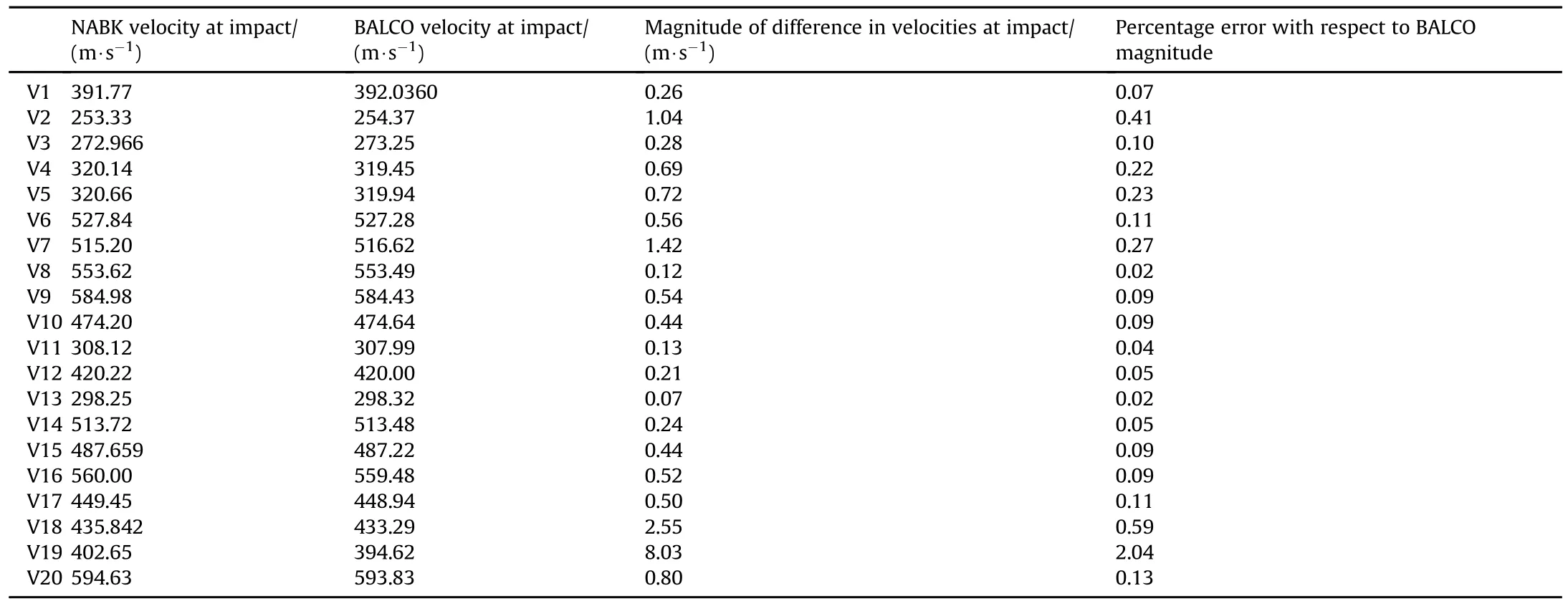
Table 12 NABK-BALCO differences in velocity at impact.

Table 13 NABK-BALCO differences in total drift angles.
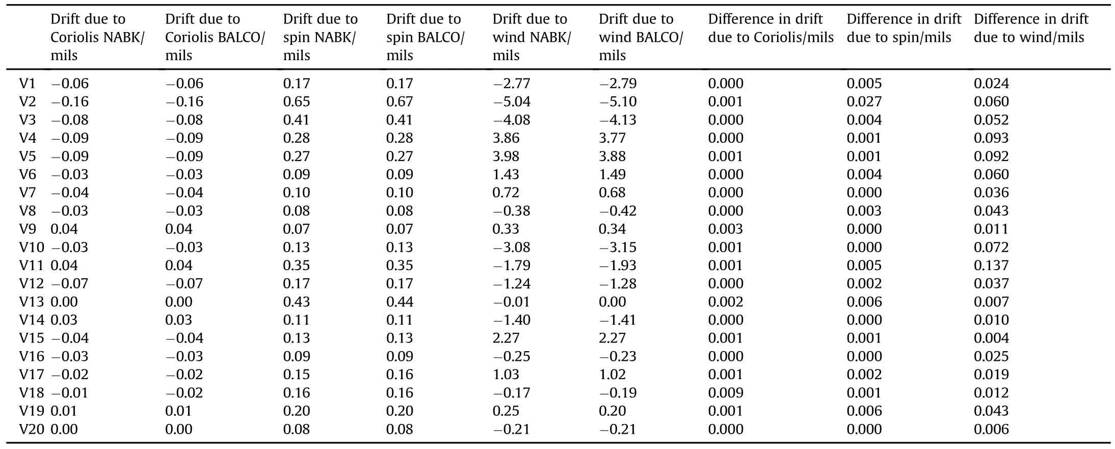
Table 14 NABK-BALCO differences in drift angles.
9.Conclusion
This reportprovides an assessmentofNATOArmaments Ballistic Kernel(NABK)firing solutions for a number of relevant sniper vignettes for the NATO 7.62×51 mm,OTBT,168 gr,Match ammunition.The work presented in this report is the first known validation of NABK data for sniper vignettes.The direct fire trajectory simulation study indicates that the results,mainly about the fire control inputs and the resulting drift,of the 6-degree-of-freedom simulations of the NATO 7.62×51 mm,OTBT,168 gr Match ammunition projectile in BALCO are in close agreement to those obtained with the 4-degree-of-freedom simulations in NABK for allthe vignettes investigated.The largest observed difference between the various parameters compared was 2%for the terminalvelocity in vignette 19.Typicaldifference in terminalvelocity was less than 0.5%.
For the vignettes studied,the fire controlinputs for BALCO and NABK resulted,in practically the same impact point for both trajectory algorithms.Relying on the BALCO-NABK comparison results presented in this paper,it is concluded that NABK is suf ficiently accurate to predict the trajectory of direct fire smallcaliber projectiles.Therefore,the use of NABK for a sniper ballistic computer can be recommended.
[1]Sowa,A.J.,“NATO Shareable Software Developing Into True Suite Supporting National Operational,Fire Control Systems”in proceedings of the 24th International Symposium on Ballistics,New Orleans,LA,September 22-26,2008.
[2]Chusilp,P,Charubhun,Weerawut and Ridluan,A.,“Developing Firing Table Software for Artillery Projectiles using Iterative Search and 6-DOF Trajectory Model”,in proceedings of the 2nd TSME International Conference on Mechanical Engineering,Krabi,Thailand,October 19-21,2011.
[3]Ortac,S.A.,Durak,U.,Kutluay,U.,Kucuk,K.and Candan,C.,“NABK Based Next Generation Ballistic Table Toolkit”,in proceedings of the 23rd International Symposium on Ballistics,Tarragona,Spain,April 16-20,2007.
[4]The Modi fied Point Mass and Five Degrees of Freedom Trajectory Models.NATO STANAG 4355.Edition 3 2009.
[5]Wey,P.,Corriveau,D.,Saitz,T.A.,de Ruijter,W.and Str¨omb¨ack,P.,“BALCO 6/7-DoF trajectory Model”in proceedings of the 29th International Symposium on Ballistics,Edinburgh,UK,May 9-13,2016.
[6]The Six/Seven Degrees of Freedom Guided Projectile Trajectory Model.NATO STANREC 4618.Edition 1 January 2014.
[7]McCoy RL.Modern Exterior Ballistics-the launch and flight dynamics of symmetric projectiles.Schiffer Military History;1999.
[8]Guide for the veri fication and validation of computational fluid dynamics simulations.AIAA G-077-1998;1998.
29 January 2017
*Corresponding author.
E-mail address:daniel.corriveau@drdc-rddc.gc.ca.
Peer review under responsibility of China Ordnance Society
http://dx.doi.org/10.1016/j.dt.2017.04.006
2214-9147/Crown Copyright©2017 Published by Elsevier Ltd.This is an open access article under the CC BY-NC-ND license(http://creativecommons.org/licenses/by-nc-nd/ 4.0/).
Received in revised form 11 April 2017
Accepted 24 April 2017
Available online 27 April 2017
- Defence Technology的其它文章
- Impact-disrupted gunshot residue:A sub-micron analysis using a novel collection protocol
- Ignition and combustion of pyrotechnics at low pressures and at temperature extremes
- A comparative study of combustible cartridge case materials
- Enhanced propellant performance via environmentally friendly curable surface coating
- An approach for optimization of the wallthickness(weight)of a thickwalled cylinder under axially non-uniform internal service pressure distribution
- Trajectory optimization of a de flectable nose missile

