Heat transfer and friction factor of Therminol liquid phase heat transfer fluid in a ribbed tube☆
Weiguo Xu,Guodong Liu*,Qinghong Zhang,Shuai Wang,Huilin Lu*,Heping Tan
School of Energy Science and Engineering,Harbin Institute of Technology,Harbin 150001,China
1.Introduction
To enhance heat transfer of fluid in smooth tube,different active and passive methods such as a flow spoiler,twisted tapes,internal ribs,helical inserts,etc.have been applied by various researchers and reviewed by Popovet al.[1].The ribbed tubes are widely used to enhance the heat transfer performance and are investigated by many researchers.Experimental data and corresponding correlations of heat transfer coefficient and friction pressure loss in ribbed tubes were proposed for different heat transfer fluids,including supercritical pressure water,steam-water,water,air,cryogenic and kerosene as listed in Table 1[2-13].The empirical correlations are proposed to predict heat transfer coefficient and friction factor of working fluids in the ribbed tubes.
Conventional fluids such as steam-water,air,water and kerosene are unable to meet the increasing demand for cooling in energy applications such as heat recovery boilers because of the limitation of temperature of working fluid[14].For the conventional heat recovery boilers the energy is transferred through tube walls to heat a working fluid.The working fluid is then passed directly through a heat exchanger.The maximum temperature of the working fluid is the predominant factor for utilization of energy because high temperature leads to high efficiencies of heat exchanger.Therminol heat transfer fluids(also known as Biphenyl/Diphenyl oxide pair)are a class of thermic fluid with applications in thermal engineering and petrochemical sectors because it provides the high performance and stability in systems with operational temperatures from-73 to 400°C[15-17].Wenhuaetal.[18]measured convective turbulent- flow heat transfer with Therminol 59-based nanofluids containing copper nanoparticles at particle volume fractions of 0.50%and 0.75%in a smooth tube.The friction factors and heattransfer coefficients were experimentally obtained and compared to the predictions from the correlation equation proposed.The effect of elevated temperature on the heat transfer coefficients was evaluated based on the measured thermophysical properties.Wanget al.[19]predicted heat transfer of Au-Therminol VP-1 nanofluids.A non-linear increase in heat transfer was observed as a function of volume fraction of nanoparticles.The convective heat transfer coefficients of Therminol 66 were measured in the smooth tube[20].They found that the predicted Nusselt number was increased with the increase of Reynolds numbers at four inlet temperatures.It is pertinent to mention that the data on convective heat transfer of Therminol heat transfer fluids are very limited.
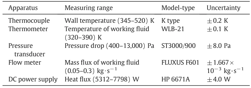
Table 1Technical properties of experimental apparatus
Therminol-55 liquid phase heat transfer fluid exists as liquid over a wide range of temperature.It is a eutectic mixture of diphenyl oxide and biphenyl,and widely used as heat transfer fluid in nonpressurized/low-pressure indirect heating system.However,the low thermal conductivity and heat capacity,and high dynamic viscosity of Therminol heat transfer fluid have negative influence on the heat transfer performance.Therefore,there are challenges and opportunities to improve the heat transfer performance of Therminol heat transfer fluid by heat transfer enhancement techniques with ribbed tubes.Unfortunately,there are extensive literatures mentioned above to investigate the performance of heat transfer and flow resistance with water,air,refrigerants and kerosene as heat transfer fluid in the ribbed tube,no sufficient knowledge about the flow mechanism and relevant correlations is available for Therminol liquid phase heat transfer fluid in the ribbed tube.The heat transfer and flow behavior of Therminol heat transfer fluid are rarely reported in ribbed tube.
Various numerical studies and approaches are used to predict flow and heat transfer characteristics in the ribbed heat exchanger tube.The flow structures and pressure drop in the tube with P-type ribs and V-type ribs were simulated using the Fluent 6.3 software[21].Water was selected as the working fluid,and SSTk-ω turbulent model was used because of the combination of thek-ω model near walls and the capability of thek-ε model in the free stream.The thermohydraulic characteristics of water were also simulated in a heat exchanger tube fitted with vortex rods and in a circular tube fitted with center-cleared twisted tapes under laminar flow conditions[22-24].The aforesaid researches indicated that 3D CFD simulation is a useful tool for analyzing,designing and optimizing heat exchangers.
The ribbed tube,as one of the most widely used enhanced heat transfer tubes,plays an important role in the design of heat exchanger systems.Up to now,limited theoretical and experimental studies of heat transfer of Therminol-55 liquid phase heat transfer fluid in ribbed tubes have been found in published literature,because of not only the complicated flow phenomena in the ribbed tube but also the complex geometric structures of the kind of tubes.In this paper,the performance of heat transfer and fluid flow of Therminol-55 liquid phase heat transfer fluid is investigated by means of numerical simulations and experiments in a ribbed tube.The heat transfer coefficient and friction factor of Therminol-55 liquid phase heat transfer fluid are measured in ribbed tube.The heat transfer and fluid flow of temperature-dependentproperty Therminol-55 liquid phase heat transfer fluid are predicted by three dimensional(3D)numerical simulations using commercial code FLUENT.Friction factor and Nusselt number correlations are presented based on experimental measurements.
2.Experimental Apparatus
The experimentalset-up is an instrumented heating system which is designed for the heat transfer studies of the Therminol-55 liquid phase heat transfer fluid.The schematic diagram of experimental set-up is shown in Fig.1.This system mainly included a test-section,a heat transfer fluid storage tank,a heat transfer fluid cooler and a flow meter.A centrifugal pump is used to circulate heat transfer fluid in the test-section.The pump is connected in arrangement to cover the entire range of flow rate.An inlet section length equalto 2500 mm is provided to ensure that the flow becomes hydrodynamically and thermally fully developed before passing through test section.After leaving the test section,Therminol-55 liquid phase heat transfer fluid rushes into a heat exchanger in order to ensure uniform mixing of fluid through outlet section.The measurements are taken in a 1Cr18Ni9Ti stainless steel ribbed tube with the inner diameterDiof 20.0 mm,outer diameterDoof 25.0 mm and length of 2000 mm.The pitchPand rib heighteare 4.5 and 1.0 mm.The helix angleθis 15 degree.The electrically heated by nichrome heater is used to heat the test section,and the uniform wall heat flux boundary condition is imposed.There is no direct contact of the nichrome heater wire with the ribbed tube wall because of a fiber glass tape insulation(electrical but not thermal)on the ribbed tube wall.The heat transfer test section is insulated using the asbestos rope and glass wool after the heater wire.Finally the jute bag is covered on the test section for further thermal insulation.
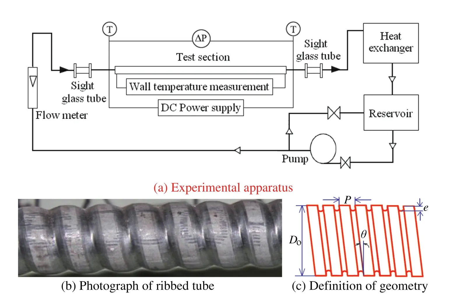
Fig.1.Schematic diagram of the experimental apparatus and test section.
The inlet and outlet temperatures of Therminol-55 liquid phase heat transfer fluid are measured using thermometers inserted into the small holes at the inlet and outlet of the test section.The holes are sealed to prevent any leakage.For the measurement of wall temperatures of the tube,K-type thermocouples are installed at nine axial locations along the test section.Two thermocouples,one at the top and the other at the bottom of the ribbed tube,are used at each location.For each temperature measuring location,one hole is drilled on the outer pipe to facilitate the passing of thermocouples leads to the temperature data collector.All the instantaneous inlet,outlet,and wall temperatures are measured.The manometers are used to measure pressure drop of Therminol-55 liquid phase heat transfer fluid at the inlet and outlet of the test-section.All instruments are calibrated prior to installation.
The local Nusselt numbers at each test condition are evaluated from measured temperatures.The heat transfer coefficient of Therminol-55 liquid phase heat transfer fluid in the ribbed tube is.

whereTwiandTfare the mean wall temperature and Therminol-55 liquid phase heat transfer fluid temperature in the test section.Ais the heat transfer area of the test section.qfis the local heat flux which is calculated on the basis of the heat flux generated by the nichrome heaterqe.

whereEandIare the voltage and current of the nichrome heater.
The energy balance equation applies to Therminol-55 liquid phase heat transfer fluid flowing in the ribbed tube at the steady condition is

whereLis the length of the test section,mis the mass flux of Therminol-55 liquid phase heat transfer fluid,andToutandTinare the outlet and inlet temperatures of Therminol-55 liquid phase heat transfer fluid.cpis the specific heat of Therminol-55 liquid phase heat transfer fluid

The pressure drop of Therminol-55 liquid phase heat transfer fluid through the ribbed tube is evaluated as the friction factor f from the pressure drop△pfacross the test section

whereufis the velocity of Therminol-55 liquid phase heat transfer fluid.ρfis the density of Therminol-55 liquid phase heat transfer fluid.

To analyze the physical characteristics and experimental data of Therminol liquid phase heat transfer fluid in the ribbed tube,some nondimensional parameters including Reynolds number and Nusselt number are defined as follows:

whereDmis the mean diameter of the ribbed tube,anduinis the inlet velocity.μfandkfare the dynamic viscosity and thermal conductivity of the Therminol-55 liquid phase heat transfer fluid.

From Eqs.(2)and(3),the coefficient of energy utilization of the test section is expressed as follows:

The voltage and current of electric input to the test section heaters are controlled by a DC power supply unit.Until the coefficient of energy utilization is controlled to be larger than(97-98)%,the readings of parameters become independent of the time and a steady state is reached.The final set of reading including temperature at all locations,pressure difference across the test section and mass flux of Therminol-55 liquid phase heat transfer fluid are recorded.The experimental data are used to calculate convective heat transfer coefficient and friction factor of Therminol-55 liquid phase heat transfer fluid in the test section.
Experimental uncertainty is determined by the method of Kline and McClintock[25].The uncertainties of parameters are summarized in Table 1.The measuring error of pressure is determined by the precision of the pressure transmitter,which is±8.0 Pa.The measuring error of flow rate was the dominant source of uncertainties in mass flux,and the precision of mass flowmeter is±1.667 × 10⁻³kg·s-1.The maximum relative uncertainty in friction factor is estimated to be 8.24%.The uncertainties in wall temperatures are estimated through the error of thermocouples,and the maximum error of thermocouples is±0.2 °C.The wall heat flux is estimated by input electric power and heat loss,and the accuracy is±4.0 W.The uncertainty in heat transfer coefficient results from the uncertainties of wall heat flux, fluid temperature and wall temperature.The maximum relative uncertainty in heat transfer coefficient is estimated to be 12.12%.As the heat transfer is enhanced,a minor uncertainty in the wall temperature or fluid temperature will result in a large uncertainty in the temperature difference between tube wall and bulk fluid,and consequently a large uncertainty in heat transfer coefficient.Thus,the uncertainty analysis not only comments on experimental results but also plays an important role in picking a suitable measurement technique(See Table 2).
3.Mathematical Model
The commercial software Fluent 6.3.26[26]is used in this work to analyze the heat transfer enhancement in the ribbed tube with Therminol-55 liquid phase heat transfer fluid.To simplify numerical simulations,the following assumptions are made:(1)the flow state is steady.Fluid is incompressible,isotropic and continuous;(2) fluid is Newtonian fluid;(3)take tube inlet Reynolds number as the overall Reynolds number;(4)the effectofgravity is negligible.In this investigation a three dimensional numerical simulation of the heat transfer and fluid flow of Therminol liquid phase heat transfer fluid is carried out in order to predict and explain the experimental observations.The conservation equations for mass,momentum and energy in the Cartesian tensor notation can be written as follows[27].
The continuity equation is


Table 2Experiments of ribbed tube for flows of different hear transfer fluids
whereuis the velocity of working fluid.The momentum equation is

where the density ρfand viscosity μfof Therminol-55 liquid phase heat transfer fluid are calculated by Eqs.(6)and(10).μtis the turbulent viscosity of working fluid.The energy equation is

where the heat capacitycpand thermal conductivitykfof Therminol-55 liquid phase heat transfer fluid are calculated by Eqs.(4)and(9).Efis the internal energy of heat transfer fluid.Prtis the turbulent Prandtl number.
For numerical simulation of turbulent flow,the turbulent viscosity μtis predicted by

wherekis the turbulence kinetic energy,andεis the turbulence dissipation rate of working fluid.Renormalization-group(RNG)k-εturbulence model is used to predict turbulence kinetic energy and dissipation rate[28,29]:

whereGkis the generation of turbulent kinetic energy due to the mean velocity gradients.The quantities αkand αεare the inverse effective Prandtl numbers forkand ε,respectively.TheRεterm in the dissipation rate equation is

whereSis the modulus of the mean rate-of-strain tensor,and defined as.

The constants in the model are known asCμ=0.0845,C1=1.42,C2=1.68,ηo=4.38 and β =0.012.
No slip condition is applied on ribbed tube wall[30].Uniform heat flux conditions are imposed on the ribbed tube wall.The inletand outlet boundary conditions are defined as per experimental setup.
The 3Dsolution domain and grid are selected by means of the hybrid method of size function and boundary layer technique.For the present work,meshing has been done using commercially available software GAMBIT 2.3.16.Tetrahedral grid and hexahedron grid are employed to generate mesh in the interior of the ribbed tube.The size and number of control volumes(mesh density)are determined and will strongly influence the accuracy of the solutions.In all cases,the grid is finer close to the ribbed tube wall where the temperature and velocity gradients are large.A careful check for the grid-independence of the numerical solutions has been made to ensure the accuracy and validity of the numerical results.Fig.2 shows the gird independence tests of three different grid numbers.Roughly,the deviations of the Nusselt number and friction factor between experimental data and simulations decrease gradually with the increase of nodes.It is found that the difference of Nusselt number and friction factor using mid and finer meshes is not obvious.This indicates the middle mesh is suitable for getting a grid independent solution.Therefore,this grid is adopted in the subsequent numerical simulations of Therminol-55 liquid phase heat transfer fluid in the ribbed tube with the compromise of computational time and solution precision.
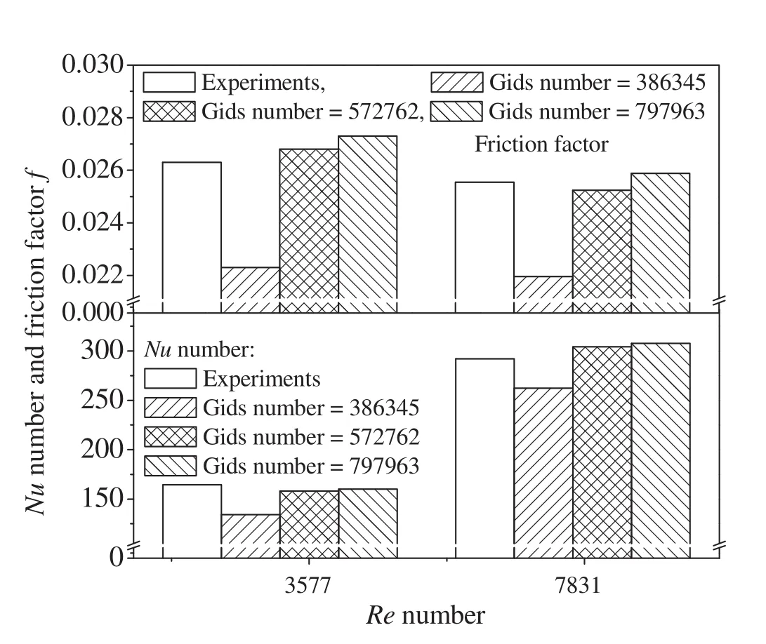
Fig.2.Gird independence tests for Nusselt number.
4.Experimental Results
4.1.Verification of the smooth tube
The present experimental results on heat transfer characteristic of Therminol-55 liquid phase heat transfer fluid in the smooth tube validate with equations of Dittus-Boelter and Geielinski as seen in Fig.3.The Dittus-Boelter correlation[31]is

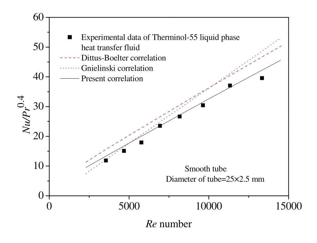
Fig.3.Validation of Nusselt number in the smooth tube.
It is valid for 0.7<Pr<160 and 104<Re<1.2×10⁵.The Geielinski correlations[32]is

It takes into account the length required to establish the flow and is valid for 1.5<Pr<500,104<Re<106and 0<di/L<1.0.Measured and calculated Nusselt number of Therminol-55 liquid phase heat transfer fluid increases with the increase of Reynolds number in the smooth tube.Obviously,the difference of Nusselt number between the experiments and calculations using Dittus-Boelter and Geielinski correlations are obvious,and the maximum relative errors between experiments and calculations are 33.8%and 37.3%,respectively because of the thermophysical properties of Therminol-55 liquid phase heat transfer fluid.
4.2.Measured heat transfer coefficient and friction factor in the ribbed tube
Fig.4 shows the variations of the Nusselt number of Therminol-55 liquid phase heat transfer fluid as a function of Reynolds numbers at the different heat fluxes.With the increase of heat flux generated by the nichrome heater,more energy is fed into the test section.The dynamic viscosity of Therminol-55 liquid phase heat transfer fluid is reduced because of high temperature,and the Reynolds number is increased.While the thermal conductivity of Therminol-55 liquid phase heat transfer fluid is decreased.Thus,the Nusselt number increases with the increase of heat flux.The Nusselt number is observed to increase with increase in Reynolds number due to the increase in turbulent intensity induced by the rib,in addition to breaking the viscous sub-layer and producing local wall turbulence.The convective heat transfer coefficient of Therminol-55 liquid phase heat transfer fluid in the smooth tube is also measured,and shown in Fig.4 as a function of Reynolds number.It is expected that the Nusselt number of Therminol-55 liquid phase heat transfer fluid in the smooth tube increases with the increase of Reynolds number.We also find that the Nusselt number of Therminol-55 liquid phase heat transfer fluid is larger in the ribbed tube than that in the smooth tube.
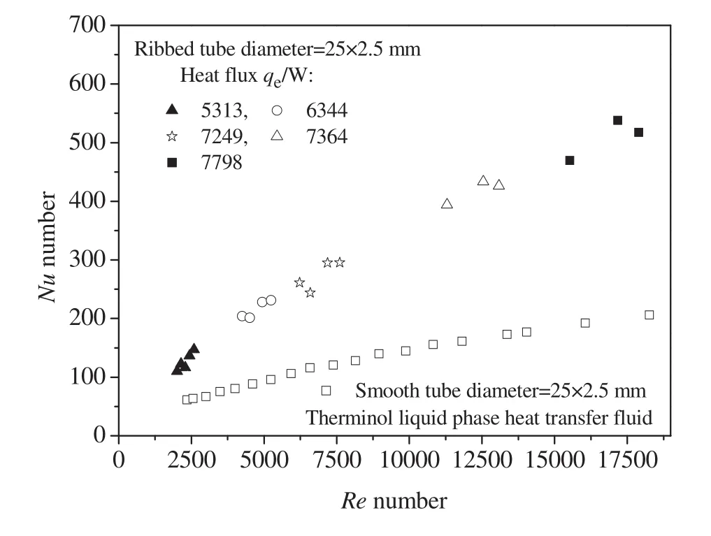
Fig.4.Pro file of Nusselt number at different Reynolds number.
The variation of friction factorfis shown in Fig.5 as a function of Reynolds number in the ribbed tube.The friction factors decrease with the increase of Reynolds number in the ribbed tube.The friction factor of Therminol-55 liquid phase heat transfer fluid in the smooth tube is also measured,and shown in Fig.5 as a function of Reynolds number.The measured friction factors of Therminol-55 liquid phase heattransfer fluid in the smooth tube decrease with the increase ofReynolds number.We also find that the friction factor of Therminol-55 liquid phase heat transfer fluid is larger in the ribbed tube than that in the smooth tube.
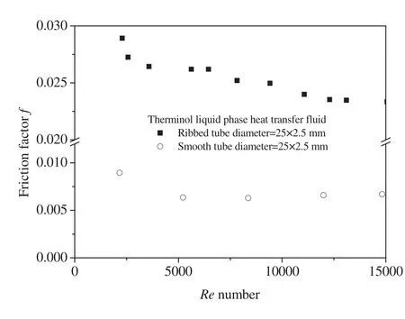
Fig.5.Pro file of friction factor as a function of Reynolds number.
5.Numerical Simulations
5.1.Flow structure
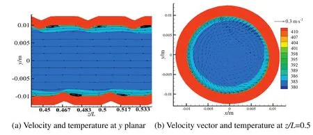
Fig.6.Simulated streamlines of velocity and temperature of heat transfer fluid.
A series of numerical simulations that give information on the flow in the longitudinal and transversal directions are performed in the ribbed tube.Fig.6 presents the simulated streamlines of vector of velocity and temperature contour of Therminol-55 liquid phase heat transfer fluid at the heat flux of 38,590 W·m-2,and inlet velocity and temperature of 0.85 m·s-1and 377.14 K,respectively.The Reynolds number is 5023.7,and the flow of Therminol-55 liquid phase heat transfer fluid is clearly in the turbulent flow.As the Therminol-55 liquid phase heat transfer fluid passes through ribs,the helical flow is formed.The vortices are generated behind ribs.These vortices interact with each other through the ribs because of the shear layer generated in the wake region.To analyze the interaction of the rear vortex,the streamlines on the vortices are considered.We notice that the rear vortex passes around the trailing edge of the rib,and then merges into the front of the next rib.The streamlines around the next rib are wrapped into a downstream and diverge as they pass through the ribs.The flow of Therminol-55 liquid phase heat transfer fluid deviates from the mainstream and swirls down due to the rib-oriented flow,inducing secondary flow and forming a turbulent mixing in the passage.The flow distances in the ribbed tube are much longer than that in the smooth tube due to the helical flow in the ribbed passage.Moreover,the streamlines of ribbed tube show the helical lines full of the downstream passage because of the variation of ribs.This implies that the turbulent mixing is enhanced in the ribbed tube.The size of vortexes behind the ribs is gradually reduced from the fully attached rib to the fully detached rib.Revolving flow along the ribs can be clearly seen in simulated streamlines because the Therminol-55 liquid phase heat transfer fluid near ribbed-wall flows along the rib's direction.
5.2.Temperature and velocity pro files
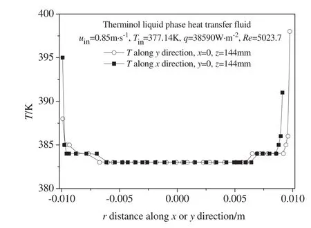
Fig.7.Distribution of temperatures of Therminol liquid phase heat transfer fluid.
As the Therminol-55 liquid phase heat transfer fluid passes through the ribbed tube the heat exchange takes place from the wall to Therminol-55 liquid phase heat transfer fluid.Fig.7 shows the distribution of temperatures of Therminol-55 liquid phase heat transfer fluid.The Therminol-55 liquid phase heat transfer fluid near the wall gets heat due to convection.This primary hot layer near the wall mixes with the cold Therminol-55 liquid phase heat transfer fluid,and heattransfer takes place due to conduction and convection.The thermal boundary layer is formed where the temperatures drop rapidly.As a result the temperature of Therminol-55 liquid phase heat transfer fluid near the wall is higher,and goes on decreasing away from the wall.In the center of the ribbed tube,it remains constant.
Fig.8 shows the profile of simulated velocity componentsuxanduy.Itcan be observed thatvelocity componentsuxanduyvary nearthe wall due to the main recirculation vortex behind the rib.The main fluid flow of the center regime in the ribbed tube is undisturbed because the streamline of the ribbed tube is approximately parallel to the straight lines.More fluid can participate in the heat transfer as the Reynolds numbers increase.
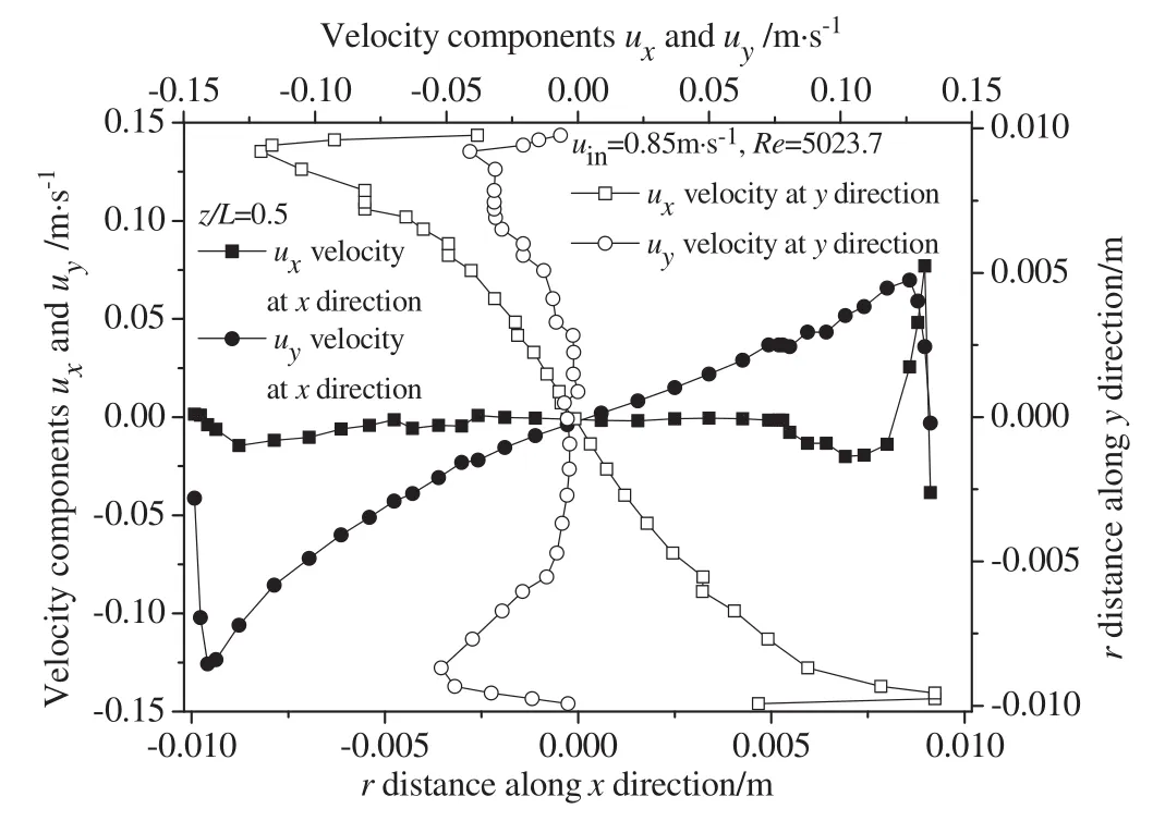
Fig.8.Profile of velocity components of Therminol liquid phase heat transfer fluid.
From simulations,the variation of heat transfer is observed when the flow of Therminol-55 liquid phase heat transfer fluid arrives at the rib.FLUENT provides tools for computing integral quantities at boundaries[26].These tools enable to find the heat transfer rate through boundaries.The heat transfer rate through a boundary can be calculated as follows:

whereqwis the convective heat transfer rate from the wall to the Therminol-55 liquid phase heat transfer fluid,and ΔAwis the wall surface area of the grid.Thus,the heat transfer rate is computed by summing the convective heat transfer rate through the windward face wall and the leeward face wall of the rib.Fig.9 shows the heat transfer rates of Therminol-55 liquid phase heat transfer fluid along the windward face wall and the leeward face wall of the rib one round.The heat transfer rates of the windward face wall and the leeward face wall of the rib increase with the increase of Reynolds numbers.The high heat transfer rate is located at the windward face wall(front of the rib)because of fluid impingement on windward face wall of the rib and intensified turbulent flow in this region.The heat transfer rate is low at the leeward face wall of the rib due to the vortices formed in the back of the rib.The heat transfer rate declines as the thermal boundary layer is growing.It may be explained that the contributions of turbulence on the heat transfer enhancement are different between the windward face wall and the leeward face wall of the rib due to the different vortex structures and thermal boundary layers.
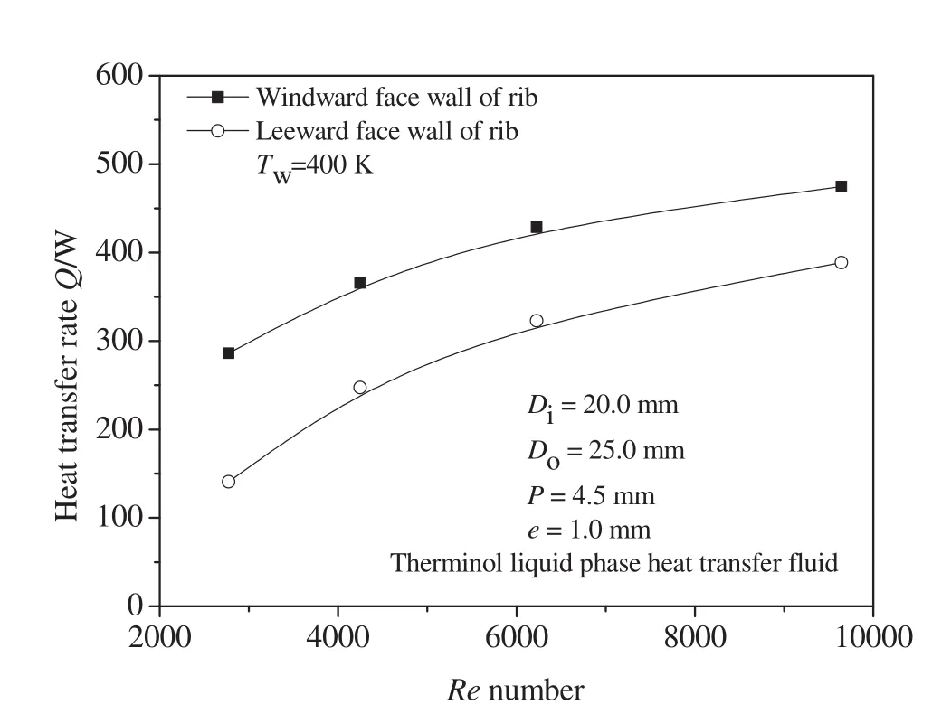
Fig.9.Heat transfer rates along the windward and the leeward faces of the rib one round.
5.3.Effects of closure models and rib height
We also solved continuity,momentum and energy equations in turbulent mode using three closure models(two equations models).They are:k-ε RNG,k-ω standard model andk-ω SST model[26].The major ways in which the SST model differs from the standard model are as follows:(1)gradual change from the standardk-ω model in the inner region of the boundary layer to a high-Reynolds number version of thek-ε model in the outer part of the boundary layer.(2)Modified turbulent viscosity formulation to account for the transport effects of the principal turbulent shear stress.The simulations have been conducted in the ribbed tube with different closure models in order to compare the results and thus highlight the heat transfer enhancement due to the effect of ribs.
Fig.10 shows the predicted Nusselt number as a function of Reynolds number.We noticed that the Nusselt number increases with the Reynolds number,whatever the turbulence model used.The standardk-ω model is an empirical model based on transport equations for the turbulence kinetic energy and the specific dissipation rate.One of the weak points of the standardk-ω model is the sensitivity of the solutions to values forkand ω outside the shear layer.The weakness of the SSTk-ω model is to effectively address the transition of the boundary layer from a laminar to a turbulent regime.The RNGk-ε model is more responsive to the effects of rapid strain and streamline curvature for certain classes of flows[26].A good agreement can be observed between simulations using RNKGk-ε and experiments,with a deviation within 8.34%,as can be seen in Fig.10.Therefore,this numerical model is then used for further ribbed tube analysis with supporting reliability of the computation.
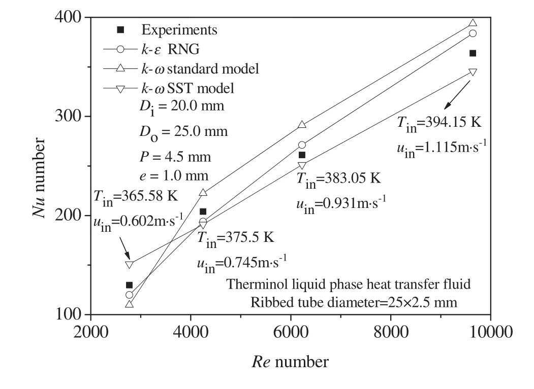
Fig.10.Predicted Nusselt number with three different closure models.
Rib heightof the ribbed tube is an important factor to get heat transfer enhancement.Asuitable rib heightofthe ribbed tube with appropriate pressure drop is in favor of improving the thermal enhancement.Fig.11 shows the profile of predicted Nusselt number and friction factor usingk-ε RNG model as a function of Reynolds number.Both Nusselt number and friction factor increase with increasing rib height in all cases.This is because,by increasing rib height,the local heat transfer near the wall is improved because the turbulence intensity induced by ribs is intensified.However,the pressure drop is also increased with the increase of rib height.
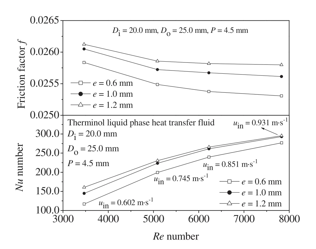
Fig.11.Profile of Nusselt number and friction factor at three rib heights.
6.Thermo-Hydraulic Performance and Physical Quantity Synergy Analysis
To assess the practical use of the ribbed tube and Therminol-55 liquid phase heat transfer fluid,the enhancement in heat transfer of the ribbed tube using Therminol-55 liquid phase heat transfer fluid is evaluated relatively to the smooth tube as a function of Reynolds number.As a common practice,it is useful to estimate the heat transfer enhancement and pressure drop increase simultaneously[33].For this purpose,the performance criterion outlined by[34]has been used,and the thermal enhancement factor is defined as

The predicted thermal enhancement factor is shown in Fig.12 as a function of Reynolds number of Therminol-55 liquid phase heat transfer fluid in the ribbed tube.The thermal enhancement factor values of ribbed tube are above unity indicating that the ribbed tubes are advantageous compared to a smooth tube.The heat transfer performance of Therminol-55 liquid phase heat transfer fluid is enhanced and the pressure losses are also increased in the ribbed tube.The thermohydraulic performance of Therminol-55 liquid phase heat transfer fluid varies with the change of Reynolds number.The results indicate that the ribbed tube is a promising tube for heat transfer enhancement at Reynolds number less than 1.0×10⁴.In order to further improve the overall thermo-hydraulic performance of ribbed tube,more parameters would be studied at high Reynolds number in the future work.
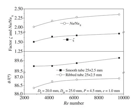
Fig.12.Profile of thermal enhancement factor and synergy angles.
Improving synergetic relation among the velocity and temperature fields is beneficial to heat transfer enhancement.Guoet al.[35-36]proposed the field synergy principle which indicates that the heat transfer rate depends not only on the velocity and temperature fields but also on their synergy which is related to an integral of the inner product of the temperature gradient and the velocity field.The physical nature of enhancing heat transfer and reducing flow resistance is directly associated with synergy angle θ.The synergy angles among velocity and temperature gradient of a fluid in the flow field is expressed as

The predicted variation of synergy angle of Therminol-55 liquid phase heat transfer fluid is also shown in Fig.12 as a function ofRenumber.As shown in the figure,the synergy angle between temperature gradient and velocity of Therminol-55 liquid phase heat transfer fluid increases with the increase of Reynolds number in the ribbed tube.The predicted synergy angle rises rapidly at the transition from laminar flow to turbulent flow.In the smooth tube,the predicted synergy angle decrease,reach minimum at the transition from laminar flow to turbulent flow,and then increase with the increase of Reynolds number.From Eq.(24),the velocity of Therminol-55 liquid phase heat transfer fluid tends to parallel with isothermals and the intersection angle between the velocity and temperature gradient becomes small.For a fixed flow rate and temperature difference,the smaller the intersection angle between the velocity and the temperature gradient,the larger the heat transfer rate.That is the reduction of the intersection angle will increase the convective heat transfer.It is found that for the ideal case the synergy angle should be equal to zero.For most of the engineering heat transfer processes,the value of synergy angle is far more than zero[37,38].Moreover,we can see that the ribbed tube has the smaller synergy angle than the smooth tube and can improve the synergy of temperature gradient and velocity fields.It is good to explain why the ribbed tube has higher heat transfer coefficients compared with the smooth tube.
7.Conclusions
The thermal performance,heat transfer enhancement and friction factor characteristics of Therminol-55 liquid phase heat transfer fluid have been investigated by means of experiments and numerical simulations in a ribbed tube.The measured Nusselt number is a mean value of 2.24 times over the smooth tube,and the measured friction factor is in the range of 2.4 and 3.5 times above the smooth tube at the test range.In addition,the empirical correlations of the Nusselt number and friction factor are also determined.The correlations fit the experimental data well and can be used within the range of experimental parameters in the paper.
The distributions of temperature and velocity of Therminol-55 liquid phase heat transfer fluid are predicted to understand the heat transfer mechanism of ribbed tube.The flow structures around the ribs and the heat transfer are explained that the windward face wall of ribs has high heat transfer coefficient due to the impinged flow that efficiently carries the heat from the wall.Simulations indicate that the rise of Nusselt number is attributed to the formation of vortices induced by ribs.Comparison of numerical results with experimental data showed that the RNGk-ε model is suitable for numerical simulation of flow and heat transfer in ribbed tube compared tok-ω standard model andk-ω SST model.
Nomenclature
Aconvection heat transfer area,m2
Cconstant
cpspecific heat at constant pressure,J⋅kg-1⋅K-1
Ddiameter,m
Evoltage of heater,V
edepth,m
ffriction factor
Ggeneration of turbulent kinetic energy,kg⋅m-1⋅s-3
hconvective heat transfer coefficient,W⋅m-2⋅K-1
Icurrent of heater,A
kturbulent kinetic energy,m2⋅s-2
kfthermal conductivity,W⋅m-1⋅K-1
Llength,m
mmass flux,kg⋅s-1
NuNusselt number
Ppitch,m
PrPrandtl number
ppressure,Pa
Qheat flux rate,W
qheat flux rate,W
ReReynolds number
Ttemperature,K
uvelocity,m⋅s-1
x,y,zcoordinate,m
ε energy dissipation,m2⋅s-3
ζ heat transfer enhancement
η coefficient
μ viscosity,Pa⋅s
ρ density,kg⋅m-3
[1]I.A.Popov,Y.F.Gortyshov,V.V.Olimpiev,Industrial applications of heat transfer enhancement:The modern state of the problem(a review),Therm.Eng.59(2012)1-12.
[2]J.W.Ackerman,Pseudoboiling heat transfer to supercritical pressure water in smooth and ribbed tubes,ASME J.Heat Transf.3(1970)490-497.
[3]S.Suhara,T.Takahashi,H.Ishikawa,T.Abe,S.Kitamura,Heat Transfer Characteristics to Supercritical Water in Ribbed Tubes,Central Research Institute of Electric Power Industry,Tokyo,Japan,1982(Report No.:281047).
[4]D.R.Tucakovic,V.D.Stevanovic,T.Zivanovic,A.Jovovic,V.B.Ivanovic,Thermal hydraulic analysis of a steam boiler with rifled evaporating tubes,Appl.Therm.Eng.27(2007)509-519.
[5]W.S.Wang,T.K.Chen,Y.Luo,H.Gu,F.Yin,Experimental study of heat transfer of ultra-supercritical pressure water in vertical upward internally ribbed tube,High Technol.Lett.13(2007)17-22.
[6]J.Pan,D.Yang,Z.Dong,T.Zhu,Q.Bi,Experimental investigation on heat transfer characteristics of low mass flux rifled tube with upward flow,Int.J.Heat Mass Transf.54(2011)2952-2961.
[7]J.Wang,H.Li,B.Guo,S.Yu,Y.Zhang,T.Chen,Investigation of forced convection heat transfer of supercritical pressure water in a vertically upward internally ribbed tube,Nucl.Eng.Des.239(2009)1956-1964.
[8]D.Yang,J.Pan,C.Zhou,X.Zhu,Q.Bi,T.Chen,Experimental investigation on heat transfer and frictional characteristics of vertical upward rifled tube in supercritical CFB boiler,Exp.Thermal Fluid Sci.35(2011)291-300.
[9]D.L.Gee,R.L.Webb,Forced convection heat transfer in helically rib-roughened tubes,Int.J.Heat Mass Transf.23(1980)1127-1136.
[10]J.G.Withers,Tube-side heat transfer and pressure drop for tubes having helical internal ridging with turbulent/transitional flow of single-phase fluid.1.Singlehelix ridging,Heat Transf.Eng.2(1980)48-58.
[11]T.S.Bavigururajan,A.E.Bergles,Development and verification ofgeneral correlations for pressure drop and heat transfer in single-phase flow in enhanced tubes,Exp.Thermal Fluid Sci.13(1996)55-70.
[12]S.K.Lee,S.H.Chang,Experimental study of post-dryout with R-134a upward flow in smooth tube and rifled tubes,Int.J.Heat Mass Transf.51(2008)3153-3163.
[13]L.Cheng,T.Chen,Y.Luo,Flow boiling heat transfer of kerosene inside ribbed tube,ASME Heat Transf.Div.351(1997)235-241.
[14]D.Huang,B.Ruan,X.Wu,W.Zhang,G.Xu,Z.Tao,P.Jiang,L.Ma,W.Li,Experimental study on heat transfer of aviation kerosene in a vertical upward tube at supercritical pressures,Chin.J.Chem.Eng.23(2015)425-434.
[15]Solutia Inc,Therminol VP1 Heat Transfer Fluids(North America)1998.
[16]P.Selvakumar,P.Somasundaram,P.Thangavel,Performance study on evacuated tube solar collector using therminol D-12 as heat transfer fluid coupled with parabolic trough,Energy Convers.Manag.85(2014)505-510.
[17]Solutia Inc,Therminol Heat Transfer Fluids by Solutia-a Selection Guide,2001.
[18]Y.Wenhua,E.V.Timofeeva,D.Singh,D.M.France,R.K.Smith,Investigations of heat transfer of copper-in-Therminol 59 nano fluids,Int.J.Heat Mass Transf.64(2013)1196-1204.
[19]C.Wang,J.Yang,Y.Ding,Phase transfer based synthesis and thermophysical properties of Au/therminol VP-1 nano fluids,Prog.Nat.Sci.Matter Int.23(2013)338-342.
[20]S.Mossaz,J.A.Gruss,S.Ferrouillat,J.Skrzypski,D.Getto,O.Poncelet,P.Berne,Experimental study on the influence of nanoparticle PCM slurry for high temperature on convective heat transfer and energetic performance in a circular tube under imposed heat flux,Appl.Therm.Eng.81(2015)388-398.
[21]N.Zheng,P.Liu,F.Shan,J.Liu,Z.Liu,W.Liu,Numerical studies on thermo-hydraulic characteristics of laminar flow in a heatexchanger tube fitted with vortex rods,Int.J.Therm.Sci.100(2016)448-456.
[22]J.Guo,A.W.Fan,X.Y.Zhang,W.Liu,A numerical study on heat transfer and friction factor characteristics of laminar flow in a circular tube fitted with center-cleared twisted tape,Int.J.Therm.Sci.50(2011)1263-1270.
[23]X.Y.Zhang,Z.C.Liu,W.Liu,Numerical studies on heat transfer and flow characteristics for laminar flow in a tube with multiple regularly spaced twisted tapes,Int.J.Therm.Sci.58(2012)157-167.
[24]W.Xu,S.Wang,H.Lu,Q.Wang,Q.Zhang,H.L.Lu,Thermo-hydraulic performance of liquid phase heat transfer fluid(Therminol)in a ribbed tube,Exp.Therm.Fluid Sci.72(2016)149-160.
[25]S.J.Kline,F.A.McClintock,Describing uncertainties in single-sample experiments,Mech.Eng.1(1953)3-8.
[26]Fluent Inc,FLUENT 6.2 user's Guide,2005.
[27]Y.Hong,X.Deng,L.Zhang,3Dnumericalstudy on compound heattransfer enhancement of converging-diverging tubes equipped with twin twisted tapes,Chin.J.Chem.Eng.20(2012)589-601.
[28]T.H.Shih,W.W.Liou,A.Shabbir,Z.Yang,J.Zhu,A new eddy-viscosity model for high Reynolds number turbulent flows—Model development and validation,Comput.Fluids24(1995)227-238.
[29]S.A.Orszag,V.Yakhot,W.S.Flannery,F.Boysan,D.Choudhury,J.Maruzewski,B.Patel,Renormalization group modeling and turbulence simulations,International Conference on Near-Wall Turbulent Flows,Tempe,Arizona,1993.
[30]X.Tang,D.Zhu,Experimental and numerical study on heat transfer enhancement of a rectangular channel with discontinuous crossed ribs and grooves,Chin.J.Chem.Eng.20(2012)220-230.
[31]F.Incropera,P.D.Dewitt,Introduction to Heat Transfer,John Wiley&Sons Inc.,1996
[32]S.K.Verma,B.N.Prasad,Investigation for the optimal thermo-hydraulic performance of artificially roughened solar air heaters,Renew.Energy20(2000)19-36.
[33]R.L.Webb,Principles in Enhanced Heat Transfer,John Wiley&Sons,New York,1994.
[34]A.E.Bergles,A.R.Blumenkrantz,J.Taborek,Performance evaluation criteria for enhanced heat transfer surfaces,ASME J.Heat Transf.2(1974)239-243.
[35]Z.Y.Guo,D.Y.Li,B.X.Wang,Anovel concept for convective heat transfer enhancement,Int.J.Heat Mass Transf.41(1998)2221-2225.
[36]Z.Y.Guo,W.Q.Tao,R.K.Shah,The field synergy(coordination)principle and its applications in enhancing single phase convective heat transfer,Int.J.Heat Mass Transf.48(2005)1797-1807.
[37]J.A.Meng,X.G.Liang,Z.X.Li,Field synergy optimization and enhanced heat transfer by multi-longitudinal vortexes flow in tube,Int.J.Heat Mass Transf.48(2005)3331-3337.
[38]W.Liu,Z.C.Liu,T.Z.Ming,Z.Y.Guo,Physical quantity synergy in laminar flow field and its application in heat transfer enhancement,Int.J.Heat Mass Transf.52(2009)4669-4672.
 Chinese Journal of Chemical Engineering2017年10期
- Chinese Journal of Chemical Engineering的其它文章
- A numerical study on heat transfer enhancement and design of a heat exchanger with porous media in continuous hydrothermal flow synthesis system
- Computationalanalysis of the flow ofpseudoplastic power-law fluids in a microchannel plate
- Investigation of droplet breakup in liquid-liquid dispersions by CFDPBM simulations:The influence of the surfactant type
- Mixed convection characteristics in lid-driven cavity containing heated triangular block
- Superhydrophobic modification of ceramic membranes for vacuum membrane distillation☆
- Synthesis,characterization and application of PVA/ionic liquid mixed matrix membranes for pervaporation dehydration of isopropanol
