区域逼近与动态图形法求解大行程液压支撑机构参数及优化
刘宏新,贾 儒,李彦龙,改广伟
区域逼近与动态图形法求解大行程液压支撑机构参数及优化
刘宏新,贾 儒,李彦龙,改广伟
(东北农业大学工程学院,哈尔滨150030)
为实现一种作业与运输兼用型地轮机构的状态转换,针对其结构特点研究一种非端部支撑的新型液压支撑方案,以满足在有限的安装空间内实现大工作行程的要求。在建立该机构力学及运动学模型的基础上,通过几何关系及动力约束条件进行参数的区域逼近;确定液压缸安装位置和参数的可行域后,运用动态图形模拟摆梁步进旋转时机构的运动情况,观测参数取值域曲线的运动状态,得出与可行边界线的交点,从而确定在液压系统压力16 MPa条件下,安装臂长度175 mm,安装臂距旋转点357 mm,液压缸缸体长度为916 mm,缸体内径为71 mm。研究及样机试用表明,非端部支撑对置双缸体液压支撑机构能够满足地轮状态转换的需要,且具有结构紧凑、工作行程大的特点。同时,该研究探索并证实了区域逼近与动态图形求解法在解决此类机构的优化与参数求解方面的可行性与有效性。
农业机械;机动性;逼近理论;状态转换;大行程;区域逼近;动态图形
0 引 言
大马力、高速度、大幅宽是现代机械化作业的重要特征。随着中国科技水平和农业机械化水平的不断提高,大型宽幅作业的农机具在中国得到了广泛的应用[1-3]。宽幅农机具可以提高单次通过面积,减少进地次数,节省时间,有利于进行复合作业和联合作业,提高作业质量,增加经济效益[4-5]。但如何保证大型宽幅农机具道路运输及作业区域间转移的安全性、通过性和方便性成为必须解决的问题[6-7]。目前,国内外主要有3大类解决方式:一是折叠,又细分为上下折叠、水平折叠和举升折叠3种;二是为大幅宽农具配套一专用于运输的牵引台车;三是双架组合式,由行走的基架与作业的托架组合成,托架可在基架上升降并能90°转向,从而实现作业与运输2种幅宽的转变[8-10]。显然:折叠机具的结构复杂,制造成本高;专用运输台车配套成本高,现场操作不便;双架组合式则结构更为复杂且成本高。
针对上述问题,东北农业大学设计了一种高机动性宽幅农具通用机架平台[11]。其地轮机构突破传统意义上的农机具机架地轮仅具限深及传动的功能,既可保证耕作深度调整方便,仿形性好,产生较大传动力,又能够方便快捷地转换状态,满足运输需要。地轮机构的变形需液压缸的驱动,为满足其小安装空间大工作行程的特点,在使用传统结构的液压缸时,一般只能采用多级液压缸或通过复杂的杆件系统转换提高液压缸的有效行程[12-16]。显然,多级液压缸价格昂贵,且缸体直径大,不宜安装;而用于传力或放大行程的杆件系统结构复杂,故障率高,误差大[17-18]。
因此,研究一种满足使用要求的单级液压支撑机构具有实际意义与理论价值,是该创新地轮机构从学术成果向应用技术转化的关键。本文拟在创新一种液压支撑方案的基础上,尝试利用区域逼近与动态图形法求解该机构的参数并优化,结合数字样机分析及样机测试,求证方案的可行性与研究方法的科学性。
1 高机动性宽幅农具通用机架平台
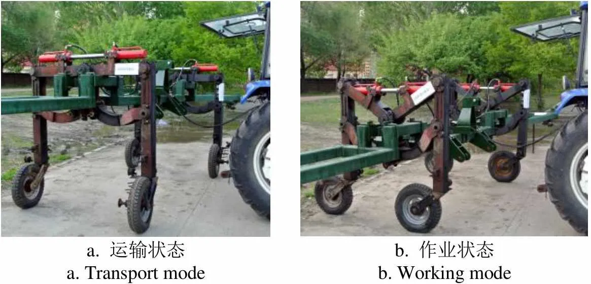
高机动性宽幅农具通用机架平台结构如图1所示。运输与作业兼用型地轮机构如图2所示,该机构可使联接在其主支座1上的机架带动作业部件实现在运输状态时的提升(如图2a所示),在作业状态时的下降(如图2b所示)。
机具的升降依靠双平行四杆结构的变形实现,共边杆3约束两立柱平行。综合考虑不同作物的耕深、机构的紧凑性和运输的稳定性,同时保证地轮机构作业状态仿形功能和运输状态安全性的条件下,确定上摆梁长度为750 mm,上摆梁旋转变换角度=[0°,53°]。高机动性宽幅农具通用机架平台拟应用于24行大豆密植平播机,根据机架与工作部件的尺寸计算质量,并考虑实际工作过程中的冲击载荷,确定单个地轮支持力1=1.47×10⁴N。

a. 运输状态a. Transport modeb. 作业状态b. Working mode
1.地轮机构 2.机架
1.Land wheel mechanism 2.Frame
注:表示运动方向。
Note:representing transport direction.
图1 高机动性宽幅农具通用机架平台
Fig.1 High-mobility universal frame platform for wide-breadth farm implements
在上摆梁上设计安装臂和液压缸,以驱动地轮机构的平行四杆结构变形,并在保证行程条件下,确定安装臂和液压缸的最优形式、位置及尺寸。
2 支撑方案
常规液压支撑方案多采用如图3a,3b所示的方式[19-23]。这2种支撑方案若使用单级液压缸,在有限的安装空间内,不能满足所需的工作行程。若要满足缸体长度与工作行程相匹配,则需增大安装距离或采用多级液压液压缸,从而导致整体机构过于庞大。因此,常规支撑方案不适用该型地轮机构。
考虑到上述常规支撑方案的局限性,提出一种非端部支撑双缸对置液压支撑机构方案,如图3c[24]。采用水平安装非端部支撑双缸体对置的方式,该支撑方案可实现驱动地轮机构的变形,节约空间占用,解决常规支撑方案的工作行程小,机构庞大的问题。由于液压缸在驱动机构变形的过程中需绕过套销4,并与上摆梁交叉,因此液压缸驱动力、缸径、缸体长度、安装臂位置及长度具有复杂的相互约束关系,有待优化示解。
a. 常规支撑方案1
a. Conventional support scheme 1
b. 常规支撑方案2
b. Conventional support scheme 2
c. 非端部支撑双缸对置液压支撑方案
c. Non-end support scheme with two opposed cylinders
1.主支座 2.上摆梁 3.安装臂(杆) 4.套销 5.液压缸
1.Main support 2.Upper swing arm 3.Mounting arm(bar) 4.Dowel pin 5.Hydraulic cylinder
图3 支撑方案
Fig.3 Support schemes
3 非端部支撑双缸对置液压支撑结构的力学分析
非端部支撑双缸对置液压支撑结构的杆件受力如图4所示。当上摆梁平置时,地轮处于运输状态,在液压缸的驱动下绕点逆时针旋转53°,地轮转换为作业状态。
机构力矩平衡方程为
∑A()=0
即
2·l'−1·l'=0 (1)
其中
l'=l·cos(2)
式中A为力矩,N·m;为机构受力,N;1为地面给予单个地轮的支持力,N;2为液压缸的推力,N;l'为点到上摆梁的距离,mm;l′为点与点距离,mm;l为上摆梁的长度,mm;为摆梁的运动范围角,(°)。
由式(2)可知,当=0°,即上摆梁平置时(如图4中实线所示状态),l′取到最大值,即l′=l;l'取到最小值,即l′=l当=0°时,将式(2)代入式(1)中,得到液压缸推力最大值2max为
式中l为安装臂的长度,mm。
双缸对置液压缸为单作用、无背压的液压缸,其活塞杆直径不受限制,液压缸内径0的计算式为[25]
式中1为液压缸工作腔压力,MPa。
将式(3)代入式(4)得到液压缸最大推力值时,缸体内径0的计算式为
地轮机构中l1、1均已知,下文均以液压缸最大推力值计算内径0,以确保缸体的可用性,故缸体内径0只与安装臂l的长度有关,且两者成反比例关系。利用上述力学分析,结合机构的各尺寸之间的约束条件及设计目标的限制,求解参数的最优解。
4 参数求解与优化
该支撑方案需满足2个设计目标:首先为保证能够使用单级缸体,期望工作行程与安装距离之比小,即/值小;其次为保证摆梁运动过程中缸体端部不与套销发生碰撞,缸体长度及其安装位置受限制。
已知条件和约束:l=750 mm;=[0°,53°],1=1.47×10⁴N;根据地轮机构的结构限制,可确定机构允许液压缸最大使用外径1max=100 mm;根据液压缸缸体材料确定缸体材料的需用应力[]=100 MPa[25];根据压力来源确定1=16 MPa;为保证缸体安装合理应满足安装距离≥150 mm,即单侧安装距离l≥75 mm。
以这2个设计目标和地轮机构的尺寸约束为限制条件,确定液压缸的最优安装位置及尺寸。如图5所示为条件约束关系及参数求解流程。
4.1 液压缸尺寸及安装位置的可行域确定
4.1.1 工作行程与安装距离比值的影响因素
当机构在=53°位置时,l′=l,l=l,l=l,l=l·tan37°,l=l/cos37°。得到几何关系表达式
l=(l+l)·sin37° (6)
l=l−l(7)
l=l−l(8)
式中l为′点到′点的距离,mm;l为点到点的距离,mm;l为点到点的距离,mm;l为点到′点的距离,mm;l为'点到点的距离,mm;l为液压缸的单侧安装距离,mm;l为′点到点的距离,mm;l为点到点的距离,mm;l为安装臂到旋转点的距离,mm;l为点到点的距离,mm。
由式(6)和式(7)联立可得出,液压缸的单侧安装距离l为
l=l·sin37°−l(1/cos37°−sin37°·tan37°) (9)
由式(8)和式(9)联立可得出,液压缸的单侧工作行程l为
l=l(1−sin37°)+l(1/cos37°−sin37°·tan37°) (10)
得到液压缸的安装距离为
=2l=2[l·sin37°−l(1/cos37°−sin37°·tan37°)](11)
得到液压缸的工作行程为
2l=2[l(1−sin37°)+l(1/cos37°−sin37°·tan37°)](12)
则工作行程与安装距离之比为
综上分析计算,确定影响目标函数/的因素为l和l,且l与目标函数成正比例关系,l与目标函数成反比例关系。因此期望l取值小,l取值大。
4.1.2 参数可行域的确定
因该机构呈对称布置,以右半侧为基准进行分析,目标优化解析如图6所示。
液压缸的壁厚为[25]
式中0=1−2,1为缸体外径,mm。
当机构处于作业状态,即=53°时,为实现缸体不与套销发生碰撞的设计目标,安装臂上的安装点应在销轴中心点所在水平线以下,⊙的半径为R=50mm,又因缸体占用一定空间,将缸体上边缘的临界位置确定为55,55为对应的缸体中心线(如图6所示)。点到缸体中心线的最小距离为
式中为安全系数,选取为1.66[25]。
l=(l·sin37°−l−l·tan37°) cos37° (16)
l=l−l·tan37°−l/cos37° (17)
注:点为旋转点;点为液压缸的安装点;⊙为销轴安装使用的可行范 围区;点为销轴中心点,即⊙的圆心;1为可行区的临界点;圆弧为点1运动轨迹;为上摆梁中心线;系列表示安装臂中心线,安装臂长度l∈[,],mm;系列表示缸体中心线;系列表示缸体上边缘,其长度l为单侧缸体长度,l∈[,],mm;系列表示缸体半径,mm,r∈[,];15为单侧缸体长度可能取值所在的 曲线;1155为单侧缸体的可行安装区;1155表示随着上摆梁的运动,单侧缸体长度可能取值点的运动轨迹所围成的区域,其中,4455为不可行区域,1122为可行区域,2244为不确定区域;3点为单侧缸体最长允许使用点。
Note: Pointis the pivot point; pointis the mounting point of the hydraulic cylinder; the circleis the feasible region of the dowel pins for safe operation;pointis the central point of the dowel pins, and the center of the circle;1is a critical point of the feasible region; arcis the motion trajectory of point1;is the centerline of the upper swing arm, mm;is the centerlines of the mounting arm, the length of the mounting arml∈[,], mm;is the centerlines of the cylinder;is the upper rims of the cylinder, with its length being the length of the one-sided cylinder,l∈[,], mm;is the radius of the cylinder, mm,r∈[,];15is a curve of the possible length value of the one-sided cylinder;1155is the feasible mounting zone of the one-sided cylinder;1155denotes the region enclosed by the motion trajectory of probable values of the one-sided cylinder length as the swing armmoves, the4455region is an infeasible region, the1122region is a feasible region, and the region2244is an uncertain region; point3is the maximum allowable point of the one-sided cylinder.
图6 目标优化解析
Fig.6 Objective optimization analysis
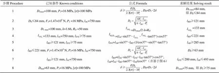
可行域具体计算步骤如表1所示。
将1 max=100 mm代入公式(14),得到液压缸的壁厚≥7.5 mm,取整为=8 mm,因此缸体内径的最大值0 max=1 max−2=84 mm;
将0≤84 mm代入式(5)中,得到l≥121 mm;
点到5点距离=1max/2·+R=133 mm;
将l≥121 mm代入式(9),得到l≥285 mm;
将l≤221 mm代入式(5),得到缸体内径的最小值0 min=63 mm,因此确定缸体内径0的取值范围为0∈[63,84];
根据公式(16)和(17),并结合图6中各参数的几何关系,当取最小值121 mm时,取到最大值200 mm,取到最大值493 mm,因此确定l与的取值范围分别为l∈[75, 200],l∈[285,493];
将0 min=63 mm代入式(14),得到壁厚≥5.5 mm,取整为6 mm,则1 min=75 mm。得到缸体外径1的取值范围为1∈[75, 100]。

表1 参数可行域计算步骤及结果
注:1为缸体外径,mm;1为液压缸工作腔压力,MPa;0为缸体内径,mm;[] 为缸体材料的许用应力,MPa;为缸体厚度,mm;1为地面给予单个地轮的支持力,N;l为上摆梁长度,mm;l为安装臂的长度,mm;为点到缸体中心线的最小距离,mm;为安全系数;R为销轴半径,mm;l为液压缸的单侧安装距离,mm;l为安装臂到旋转点的距离,mm;为5点到5点的距离,mm;l为点到系列点的距离,mm。
Note:1is the outside diameter of the hydraulic cylinder, mm;1is the pressure of the hydraulic cylinder working chamber, MPa;0is the inside diameter of the cylinder, mm;[] is the allowable stress of the cylinder material, MPa;is the wall thickness of the hydraulic cylinder, mm;1is the ground supporting force of a single land wheel, N; lis the length of the upper swing arm, mm;lis the length of the mounting arm , mm;is the minimum distance between pointand the centerline of the hydraulic cylinder, mm;is safety factor; Ris radius of pin, mm; lis the one-sided mounting distance of the hydraulic cylinder, mm; lis the distance of the mounting arm and the turning point, mm;is the distance between point Band point D, mm; lis the distance between pointand point, mm.
单侧缸体的总长0为[25]
0=/2++++
即
0=l·(1−sin37°)+l·(1/cos37°−sin37°·tan37°)+20+35(18)
式中为活塞宽度,一般为(0.6~1)0,mm;为活塞杆导向长度,一般为(0.6~1.5)0,mm;为活塞杆密封长度,由密封方式确定,mm;为其他长度,mm。其中,本文选取活塞宽度=0.80;由于双缸对置液压缸的行程较大,为减小挠度和保证稳定性,选取活塞杆导向长度=1.20;采用密封圈进行密封,确定活塞杆密封长度=10 mm;隔套和单侧缸体前后缸盖等其他长度=25 mm。
因考虑其经济性并减轻机构质量,首先期望缸体外径1取可行域的最小值,且因l与1成反比例关系,希望l长度取可行域内的最大值。经4.1.1节分析可知,希望l长度取可行域内的最小值。当销轴中心点到缸体上边缘的距离l(为正整数)值确定时,系列的位置一定,此时系列取最小值,即l=75 mm时,l取到最大值,l取到最小值。根据各尺寸的可行域,确定0∈[413, 498],即图6中以点为原点的1和5的横坐标值=413 mm,=498 mm。
在l∈[121,221]范围内随机取点,计算出这些随机点对应的l和0值,代入式(18),描绘出单侧缸体长度可能取值所在的曲线15,则1155为单侧缸体的可行安装区,如图6所示。1155表示随着上摆梁的运动,单侧缸体长度可能取值点的运动轨迹所围成的区域,例如11为缸体端点1随摆梁运动所形成的运动轨迹。以图6所示运动轨迹为分析依据,完全位于圆弧安全区外侧的4455区在运动中与⊙存在干涉,所以为不可行区域;完全位于圆弧安全区内侧的1122区在运动中与⊙完全不干涉,所以为可行区域;中间区域2244为不确定区域。为确定机构尺寸的最优解,需要确定不确定区域2244中的可行域。
4.2 最优参数确定
4.2.1 支撑方案平面运动机构建立
利用计算机辅助三维交互应用(computer aided three-dimensional interactive application,CATIA)草图约束动画模拟如图3c所示非端部支撑双缸对置液压支撑机构方案的运动情况,机构简图运动模型及对应的关键尺寸约束如图7所示[26-27],尺寸单位为mm。运动机构中固定件主支座、主运动件摆梁和安装臂为全约束,包括尺寸约束和位置约束。液压缸为运动件,固定约束两侧缸体和活塞的长宽尺寸。运动过程中缸体的安装位置固定不变,因此在草图中约束安装销轴中心与单侧缸体的端部距离l,如图7中的尺寸值75 mm。安装臂随上摆梁在[0°,53°]范围内做往复摆动,液压缸内的活塞相对于液压缸做伸缩运动,活塞的伸缩运动驱动摆梁的摆动,故摆梁运动的角度范围的端点值为草图约束动画的“参数”。利用上述的动态图形的方法对该机构进行虚拟仿真,观察其运动状态。该方法能够更加直观地反映机构的运动状态、方式,方便优化及修改方案。
4.2.2 最优解获取
针对图6所示的目标优化解析可采用上述动态图形的方法来寻找最优目标,尺寸约束如图8a所示,单位为mm。⊙与圆弧的切点1为可行区的临界点,摆梁运动时曲线15上有唯一的一点与点1相交,这一点即为单侧缸体长度最大允许使用点,利用草图约束动画功能模块,模拟可行缸长范围内液压缸运动全过程,逐步逼近找到该点。针对非端部支撑双缸对置液压支撑机构方案的草图动画设置有如下要点:
4)可行区临界点1为运动元素上的固定点,约束为定值。
a. 运动机构简图及尺寸约束
a. Motion mechanism diagram and dimension constraints
b. 临界点与曲线相交结果
b. Result of Critical point and curve intersection
注:点为旋转点;点为液压缸的安装点;⊙为销轴安装使用的可行范围区;1为可行区的临界点;为上摆梁;为安装臂;表示缸体中心线;3表示缸体上边缘,其长度为单侧缸体长度,mm;3表示缸体半径,mm;3点为上摆梁运动过程中,单侧缸体长度可能取值所在的曲线与临界点1的相交点。
Note: Pointis the pivot point; pointis the mounting point of the hydraulic cylinder; the circleis the feasible region of the dowel pins for safe operation;1is a critical point of the feasible region;is the upper swing arm;is the mounting arm;is the centerlines of the cylinder;3is the upper rims of the cylinder, with its length being the length of the one-sided cylinder, mm;3is the radius of the cylinder, mm; point3is the intersection point of the curve of the possible length value of the one-sided cylinder and critical point1during the swing armin motion.
图8 运动机构简图约束及其优化结果
Fig.8 Constraints and optimization result of motion mechanism diagram
如图8b所示,临界点与曲线相交位置发生在摆梁运动到与水平位置呈33.3°时。则单侧缸体长度最大允许使用点为图6中3点,以点为原点的坐标为3(458,432)。
由此确定单侧缸体长度为0==458 mm,l= 357 mm,l=175 mm,缸体外径1=85 mm,内径0= 71 mm。
5 虚拟仿真与样机测试
5.1 虚拟样机仿真分析
根据优化结果及液压缸相关技术标准设计非端部支撑双缸对置液压支撑机构,各参数为:单侧缸体长度0=458 mm,单侧工作行程l=282 mm,缸体外径1=85 mm,缸体内径0=71 mm,缸体厚度=7 mm,缸体单侧安装距离l=75 mm,安装臂长度l=175 mm,安装臂距旋转点距离l=357 mm。
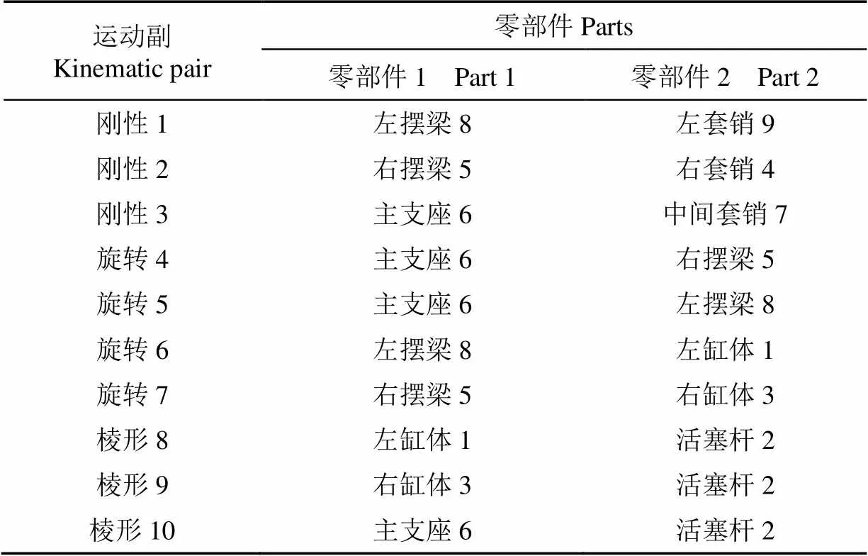
利用优化的机构参数,对液压支撑机构进行结构设计,并完成三维虚拟装配,进行运动学仿真分析,以验证理论模型[28]。按照表2和图9a创建运动副,定义主支座6为固定件,驱动“旋转.4”的角度为命令,以角度范围[0°,53°]建立运动模拟,完成运动仿真机构。分别以图9a中点1和点2作为“要绘制轨迹的要素”,以主支座6为“参考产品”,得到套销上点1和缸体上边缘端点相对于主支座的运动轨迹,如图9所示。将图9b中仿真轨迹与图8b中理论分析获得最优轨迹结果(即为图6中曲线33和圆弧)进行对比,两者轨迹基本重合,虚拟仿真与理论分析一致。同时,通过观察仿真运动过程可知,机构的安装位置和设计参数可满足状态转换的技术要求。

表2 支撑机构运动仿真模型运动副及分析要素
机构在状态转换过程中部件之间无碰撞现象是设计的目标之一,因此,对可能发生碰撞的关键部件,套销和缸体进行干涉仿真分析,利用“扫掠包络体”描绘机构运动部件几何体在整个运动过程中所扫掠的空间范围[29-31]。生成以固定件“主支座”为参考产品,分别以“左侧液压缸缸体”、“右侧液压缸缸体”、“左套销”和“右套销”为扫掠对象的扫掠包络体,分析结果如图10a所示;以右侧为基准进行分析,生成以“右套销”为参考产品,“右侧液压缸缸体”为扫掠对象的相对扫掠包络体,分析结果如图10b所示。
a. 仿真模型
a. Simulation model
b. 仿真轨迹
b. Simulation trajectory
1.左缸体 2.活塞杆 3.右缸体 4.右套销 5.右摆梁 6.主支座 7.中间套销 8.左摆梁 9.左套销
1.Left hydraulic cylinder 2.Cylinder rod 3.Right hydraulic cylinder 4.Right dowel pin 5.Right swing arm 6.Main support 7.Middle dowel pin 8.Left swing arm 9.Left dowel pin
注:点1为套销上点1,点2为缸体上边缘端点,参考图6。
Note: Point 1 is point1on the dowel pin, point 2 is pointon the upper edge of the cylinder, and refer to Fig.6.
图9 液压支撑机构虚拟样机仿真模型及轨迹
Fig.9 Simulation model and trajectory of virtual prototype of the hydraulic support mechanism
a. 扫掠包络体1分析结果
a. Analysis result of swept volume 1
b. 扫掠包络体2分析结果
b. Analysis result of swept volume 2
1.右侧液压缸缸体的扫略包络体 2.右套销
1.Swept volume of the right cylinder 2.The right dowel pin
注:包络体1为“左侧液压缸缸体”、“右侧液压缸缸体”、“左套销”和“右套销”相对于“主支座”在整个运动过程中所扫掠的空间范围;包络体2为“右侧液压缸缸体”相对于“右套销”在整个运动过程中所扫掠的空间范围。
Note: Swept volume 1 is sweeping spatial scales of the left cylinder, the left dowel pin, the right cylinder, and the right dowel pin relative to the main support in the process of the whole movement; Swept volume 2 is sweeping spatial scale of the right cylinder relative to the right dowel pin in the process of the whole movement.
图10 干涉仿真结果
Fig.10 Interference simulation result
根据扫掠结果可知,液压缸缸体与套销在运动过程中同时间点包络体无相交,则部件间无碰撞,机构设计及其参数符合要求。
5.2 样机试制及测试
试制以非端部支撑双缸体对置液压驱动机构与运输与作业兼用型地轮为特征的高机动性宽幅农具通用机架平台。通过机架主梁加载及液压缸伸缩测试,液压支撑机构可按设计要求驱动地轮机构变形,无干涉与碰撞现象,升程及调整范围满足作业及运输2种状态的技术要求,液压缸运行稳定,如图11a,11b所示;通用机架工程应用于大型农具24行大豆密植平播机,实现在全载荷和动载荷条件下正常运输和作业,未见机构部件断裂、变形,如图11c所示。田间作业及道路运输各状态均实现了研究的目标,非端部支撑双缸体对置液压驱动机构表现良好,可靠。

a. 运输状态a. Transport modeb. 作业状态b. Working mode
c. 应用于24行大豆密植平播机
c. Application of 24 rows soybean precision parallel planter
图11 样机测试及工程应用
Fig.11 Prototype test and engineering application
6 结 论
1)非端部支撑双缸体对置液压支撑机构,与常规液压缸支撑方案相比,有更大的行程比,结构紧凑,能够适应运输与作业兼用型地轮机构上狭小的初始安装空间及有限的运动空间。
2)针对本文地轮机构的结构及相关数据,液压支撑机构优化参数为:安装臂的长度为175 mm,安装臂距旋转点357 mm,液压缸缸体长度为916 mm,缸体内径为71 mm。
3)区域逼近与动态图形组合求解法在解决此类问题上具有明显的优越性与便捷性。区域逼近法用于确定参数可行域,动态图形求解最优参数。区域逼近的效率及有效性取决于约束条件的全面体现以及相互关系的清晰表达,是动态图形求解与参数优化的基础。
[1] 卢秉福,韩卫平,朱明. 农业机械化发展水平评价方法比较[J]. 农业工程学报,2015,31(16):46-49. Lu Bingfu, Han Weiping, Zhu Ming. Comparision of evaluation method for agricultural mechanization development level[J]. Transactions of the Chinese Society of Agricultural Engineering (Transactions of the CSAE), 2015, 31(16): 46-49. (in Chinese with English abstract)
[2] 罗锡文. 对加速我国农业机械化发展的思考[J]. 农业工程,2011,1(4):1-8. Luo Xiwen. Thoughts on accelerating the development of agricultural mechanization in China[J]. Agricultural Engineering, 2011, 1(4): 1-8. (in Chinese with English abstract)
[3] 甘露,潘亚东,孙士明. 我国农业机械化发展态势分析[J]. 农机化研究,2011(2):203-208. Gan Lu, Pan Yadong, Sun Shiming. Analysis of the development trend of agricultural mechanization in China[J]. Journal of Agricultural Mechanization Research, 2011(2): 203-208. (in Chinese with English abstract)
[4] 陆会茹,秦海生. 推进农业生产全程机械化的形势与对策分析[J]. 现代农机,2015(6):33-35.
[5] 张华光. 2015年,农机市场十大关键词[J]. 农机市场,2016(1):26-28.
[6] Davis W M. Folding Mechanisms Overview[R]. SAE Technical Paper, 1985.
[7] Bryson J R., Clark J, Vanchan V. Handbook of Manufacturing Industries in the World Economy[M]. Cheltenham: Books, 2015: 229-244.
[8] Pratt R L. Agricultural implement frame having a transport configuration and a working configuration: Patent 6, 321, 852[P]. 2001-11-27.
[9] Kinzenbaw J E, Barry A F, Deckler H C. Agricultural implement with common mechanism for raising/lowering and rotating a lift frame about a vertical axis: Patent 5, 346, 019[P].1994-09-13.
[10] Kinzenbaw J E. Agricultural implement with raisable lift frame rotatable about vertical axis: Patent 4, 721, 168[P]. 1988-01-26.
[11] 刘宏新,宋微微,周向荣. 大型农机具地轮作业状态与运输状态转换结构:201110462375.6 [P]. 2012-07-18.
[12] Wangikar S, Patil A, Patil S. Design and buckling analysis of multistage hydraulic lifter[J]. Design and buckling analysis of multistage hydraulic lifter, 2015, 2(8): 1953-1957.
[13] 黎立萍,柳雪春. 避免多级液压缸运行阶跃的液压装置的设计[J]. 起重运输机械,2013(9):28-30.
[14] Lindahl G M, Nelson E H, Mellor M L R. Hydraulic strut assembly for semi-levered landing gear: Patent Application 13/474,332[P]. 2012-05-17.
[15] Guido H. Multiple-stage hydraulic cylinder: Patent 5,613,418[P]. 1997-03-25.
[16] Tian Hongyu, Zhang Ziyi. Design and simulation based on pro/e for a hydraulic lift platform in scissors type[J]. Procedia Engineering, 2011, 16: 772-781.
[17] 赵静一,陈鹏飞,郭锐. 自行式液压货车非对称转向系统设计[J]. 机械工程学报,2012,48(10):160-166. Zhao Jingyi, Chen Pengfei, Guo Rui. Design of asymmetry steering system for self-propelled hydraulic transporter[J]. Journal of Mechanical Engineering, 2012, 48(10): 160-166. (in Chinese with English abstract)
[18] 郑恩来,张航,朱跃,等. 含间隙超精密压力机柔性多连杆机构动力学建模与仿真[J]. 农业机械学报,2017,48(1):375-385. Zheng Enlai, Zhang Hang, Zhu Yue, et al. Dynamic modeling and simulation of flexible multi-link mechanism including joints with clearance for ultra-precision press[J]. Transactions of the Chinese Society for Agricultural Machinery, 2017, 48(1): 375-385. (in Chinese with English abstract)
[19] 曹芳芳,范元勋. 关于连杆组合式举升机构优化设计数学模型的探讨[J]. 现代机械,2015(5):23-35.
[20] 李政,李尚平,周建阳,等. 小型甘蔗收获机集蔗机构的设计与仿真[J]. 农机化研究,2014(12):87-91. Li Zheng, Li Shangping, Zhou Jianyang, et al. Design and simulation on sugarcane collection organization of small-scale sugarcane harvester[J]. Journal of Agricultural Mechanization Research, 2014(12): 87-91. (in Chinese with English abstract)
[21] 许平勇,曹鹏举. 平行杆翻转举升机构及液压缸铰支点设计[J]. 起重运输机械,2008(5):23-26.
[22] 苑风霞,司志远. 自卸汽车举升机构设计[J]. 赤峰学院学报:自然科学版,2014,30(5):89-91.
[23] 陈志伟,金波,朱世强,等. 液压驱动仿生多足机器人单腿设计与试验[J]. 农业工程学报,2016,32(5):36-42. Chen Zhiwei, Jin Bo, Zhu Shiqiang, et al. Design and experiment of single leg of hydraulically actuated bionic multi-legged robot[J]. Transactions of the Chinese Society of Agricultural Engineering (Transactions of the CSAE), 2016, 32(5): 36-42. (in Chinese with English abstract)
[24] 刘宏新,宋微微,周向荣. 双缸体对置式非端部铰接支承液压油缸:201110462374.1[P]. 2012-07-04.
[25] 阎邦椿.机械设计手册[M],5版. 北京:机械工业出版社,2010:65-66,249-250.
[26] 刘宏新,徐高伟,孟永超. CATIA三维设计基础与应用[M]. 北京:机械工业出版社,2014:82-88.
[27] Richard Cozzens. CATIA V5 Workbook Release 19[M]. Mission: SDC Publications, 2009: 3.35-3.36.
[28] 刘宏新,宋微微. CATIA数字样机运动仿真详解[M]. 北京:机械工业出版社,2013:190-196.
[29] Abdel-Malek K, Yang J, Blackmore D, et al. Swept volumes: fundation, perspectives, and applications[J]. International Journal of Shape Modeling, 2006, 12(1): 87-127.
[30] Rossignac J, Kim J J, Song S C, et al. Boundary of the volume swept by a free-form solid in screw motion[J]. Computer-Aided Design, 2007, 39(9): 745-755.
[31] 江笑龙,王广官,单岩,等. 凸包STL 模型的运动包络体计算及其应用[J]. 机械设计与研究,2014,30(3):5-7. Jiang Xiaolong, Wang Guangguan, Shan Yan, Song Xiaowen. An algorithm for generating enveloping solid of the convex STL model and its application[J]. Machine Design and Research, 2014, 30(3): 5-7. (in Chinese with English abstract)
Parameters solving and optimization of long working stroke hydraulic support mechanism using regional approximation and dynamic graphical solution
Liu Hongxin, Jia Ru, Li Yanlong, Gai Guangwei
(Engineering College, Northeast Agricultural University, Harbin 150030, China)
As a result of substantial improvements in agricultural mechanization in China, large farm implements have been widely utilized. However, a problem has arisen concerning how to guarantee safety, effectiveness and convenience when such wide-breadth farm implements switch between road transport and operational modes. At present, there are 3 methods of resolution: Folded frames, which can be subdivided into supero-inferior fold, horizontal fold and lifting fold; a trailer for longitudinal traction along the girder of a wide-breadth farm implement; and combined double-frame agricultural implement with common mechanism for raising/lowering and rotating a lift frame about a vertical axis. Nevertheless, folded frames have complex structures and are expensive to manufacture; a dedicated shoring trailer has to be furnished, and field operation is very inconvenient; and the complex structure of combined double frames are more expensive. To address these technical problems, a high-mobility universal frame platform for wide-breadth farm implements, which can benefit operation and transport, was designed at Northeast Agricultural University. Its land wheel mechanism outperforms conventional land wheels on the frames of farm implements that only have depth-limiting and transmission functionality. The land wheel mechanism ensures easy tilling depth adjustment, good conformality, the ability to produce a large driving force, and convenient and quick switch modes. To realize the mode switching of land wheel mechanism for operation and transport purposes, a novel hydraulic support scheme was selected based on a part of trunnion mounted cylinder on a common rod. It adapted to the structural characteristics of the land wheel actuation device that required a long working stroke within a limited mounting space. Toward mechanics and kinematic models for this mechanism, support structure parameters were regionally approximated according to a spatial geometric relationship and subject to dynamic constraints. After the feasible region of the mounting position and dimensions of the hydraulic cylinder were determined, a dynamic graphical solution was used to simulate the motion situation of mechanism. As the swing arms rotated stepwise, the curve describing the cylinder length on one side was observed to find its point of intersection with a feasible boundary. The optimal solutions for the mounting position and cylinder dimensions could be determined using this information. When the hydraulic system pressure was 16 MPa, the length of the mounting arm was found to be 175 mm, the mounting arm was 357 mm away from the pivot point, the length of the hydraulic cylinder was 916 mm, and the inside diameter of the cylinder was 71 mm. The study and prototype trial indicate that the non-end supported opposed twin-cylinder hydraulic support mechanism enables the land-wheel mode to switch and is characterized by a compact structure and a long working stroke. The study also demonstrates that regional approximation and dynamic graphical solutions can be effectively used in the optimization and parameter solving for such mechanisms.
agricultural machinery; maneuverability; approximation theory; mode transition; long stroke; regional approximation; dynamic graphical solution
10.11975/j.issn.1002-6819.2017.04.001
S220.2; S220.34
A
1002-6819(2017)-04-0001-09
2016-02-14
2017-01-03
黑龙江省博士后科研启动基金(LBH-Q14024);公益性行业(农业)科研专项(201303011)
刘宏新,男,教授,博士生导师,研究方向为现代农业装备、数字化设计、CAD&CAE。哈尔滨 东北农业大学工程学院,150030。Email:Lcc98@neau.edu.cn
刘宏新,贾儒,李彦龙,改广伟. 区域逼近与动态图形法求解大行程液压支撑机构参数及优化[J]. 农业工程学报,2017,33(4):1-9. doi:10.11975/j.issn.1002-6819.2017.04.001 http://www.tcsae.org
Liu Hongxin, Jia Ru, Li Yanlong, Gai Guangwei. Parameters solving and optimization of long working stroke hydraulic support mechanism using regional approximation and dynamic graphical solution[J]. Transactions of the Chinese Society of Agricultural Engineering (Transactions of the CSAE), 2017, 33(4): 1-9. (in Chinese with English abstract) doi:10.11975/j.issn.1002-6819.2017.04.001 http://www.tcsae.org

