Wind tunnel simulation of pollutant dispersion inside street canyons with galleries and multi-level flat roofs*
Yuan-dong HUANG (黄远东), Ning-bin ZENG (曾宁斌), Ze-yu LIU (刘泽宇), Ye SONG (宋也),
Xuan XU (许璇)
School of Environment and Architecture, University of Shanghai for Science and Technology, Shanghai 200093,China, E-mail: huangyd@usst.edu.cn
In this study, the pollutant dispersion within street canyons is studied by experiments conducted in an environmental wind tunnel. The vehicular exhaust emissions are modeled using a line source. The pollutant (smoke) concentrations inside the canyons are measured based on a light scattering technique. The pollutant concentrations within the four different street canyons containing the galleries and the three-level flat-roofs under both the isolated and urban environments are obtained and discussed. For each of the four canyon configurations investigated, it is found that there is an obvious discrepancy between the pollutant dispersion patterns under the isolated environment and the urban environment. The three-level flat roof is found to significantly influence the pollutant distribution pattern in a street canyon. In order to clarify the impacts of the wedge-shaped roofs on the pollutant dispersion inside an urban street canyon of an aspect ratio of 1.0, the pollutant distributions inside urban street canyons of three different wedge-shaped roof combinations are measured and analyzed. It is revealed that the pollutant distribution pattern inside the urban street canyon of an aspect ratio of 1.0 is influenced greatly by the wedge-shaped roof, especially, when an upward wedge-shaped roof is placed on the upstream building of the canyon. Images from this study may be utilized for a rough evaluation of the computational fluid dynamics(CFD) models and for helping architects and urban planners to select the canyon configurations with a minimum negative impact on the local air quality.
street canyon, pollutant dispersion, wind tunnel experiments, three-level flat roof, line source
Introduction
A “street canyon” generally refers to a relatively narrow street in-between buildings that line up continuously along both sides[1]. Within the street canyons,the pollutants emitted from motor vehicles have adverse impacts on the health of pedestrians, cyclists, drivers, vehicle passengers and nearby residents[2]. Since the traffic emissions constitute a major source of air pollution in most urban areas, the dispersion of vehicular exhausts inside and over street canyons becomes an important aspect of urban air-quality studies.
So far, full-scale field measurements, wind tunnel experiments, and computational fluid dynamics (CFD)simulations were widely used to investigate the wind flow and the pollutant distributions in street canyons. These studies focused primarily on the effects of the street-canyon geometry[3-5], the ambient wind[5-7], the thermal conditions[8-10]and the traffic-induced turbulence[11-13]on the wind flow pattern and the pollutant distributions inside street canyons. In the investigation of the effects of the canyon geometry on the flow and the dispersion within street canyons, the previous considerations focused on the street width to building height aspect ratios, the symmetric and asymmetric building placements (for even, step-up and step-down canyons), as well as the building roof shapes. In those considerations, the rectangular buildings are commonly assumed and the roof shapes applied are the vaulted,trapezoidal, slanted and wedged roofs. In the real urban environments, some street canyons may have complicated geometries with galleries and multi-level flatroofs[14,15], which, up to now, have not been well studied. In recent years, the pollutant dispersion within urban street canyons formed by wedge-shaped roof buildings was investigated systematically by CFD approaches[16,17]but no wind tunnel experimental results were reported. The findings from the CFD simulations need to be validated by the wind tunnel measurements.

Fig.1 Wind tunnel at the School of Environment and Architecture, University of Shanghai for Science and Technology
The aim of the present study is to reveal the effects of multi-level flat roofs and galleries on the pollutant distributions inside both the isolated and urban street canyons and to clarify the impacts of wedgeshaped roofs on the pollutant distributions inside urban street canyons by means of the wind tunnel experiments. The wind tunnel models of street canyons with galleries and three-level flat roofs as well as the wind tunnel models of urban street canyons with wedgeshaped roofs are constructed at a geometric scale of 1:100. A line source emitting smoke (pollutant) is designed for simulating the vehicular exhaust emissions. The pollutant concentrations inside the wind tunnel models of the street canyons are obtained using a light scattering technique[18,19]. The images from the light scattering technique are processed to reveal the pollutant distribution pattern inside each street canyon studied.

Fig.2 Spires and coarse roughness elements in the wind tunnel
1. Experimental set-up and measurement techniques
1.1Introduction to the wind tunnel facility
The experiments are performed in the environmental wind tunnel at the School of Environment and Architecture, University of Shanghai for Science and Technology. This facility is an open circuit wind tunnel of suction type with a total length of approximately 33 m. It consists of an air inlet fitted with honeycombs and meshes, a stable section, a contraction section with a contraction ratio of 4:1, a working section, a transition section, an axial fan and an air outlet (Fig.1). The dimension of the working section is 18 m long, 2.5 m wide and 1.8 m-2.1 m high (the ceiling of the working section has a slope of 1:60 allowing the compensation of pressure losses in the direction of the stream). The air speed in the working section can be adjusted in the range of 0.5 m/s-20 m/s. The six spires installed at the entrance of the working section and the coarse roughness elements across the working Section 2 m downstream the spires are utilized to initiate the atmospheric boundary-layer flow(Fig.2).
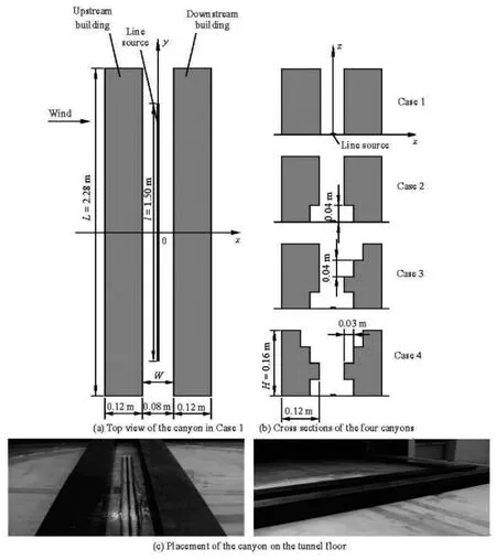
Fig.3 Four different isolated street canyon configurations
1.2Wind tunnel models of street canyons
1.2.1Wind tunnel models of street canyons with galleries and three-level flat roofs
In the present study, four different isolated street canyon configurations are adopted as shown in Fig.3. The building models are constructed of wood at a geometric scale of 1:100. The wood blocks are painted in black to avoid the reflections of light from the laser sheet. In each isolated canyon case, two building rows with length L=2.28mand height H=0.16m are placed perpendicularly to the approach flow. Inbetween the two building rows, a smoke-emitting line source with length l=1.5m is embedded at the center of the canyon floor for simulating the release of traffic exhausts. The isolated canyon in Case 1 is considered as the reference canyon, represented by the normalized building dimensions L/H=14.25 (long canyon) and B/H (building width/building height) =0.75, and the aspect ratio /WH (street width/building height) =0.5 (deep canyon). From this basic canyon configuration in Case 1, the canyon with two galleries (Case 2), the canyon containing two galleries and the downstream building with three-level flat roof(Case 3), and the canyon containing two galleries and upstream and downstream buildings with three-level flat roofs (Case 4) are constructed. Each gallery is 2.28 m in length, 0.03 m in width and 0.04 m in height in Cases 2-4. The dimension of each step-like structure for the three-level flat roofs in Cases 3 and 4 is 2.28 m long, 0.03 m wide and 0.04 m high.
In the current study, four different urban (nonisolated) street canyon configurations are also considered as illustrated in Fig.4. Here, the four urban street canyons are constructed simply by placing additional buildings (each building is 2.28 m long, 0.16 m wide and 0.16 m high) at both upstream and downstream of the isolated canyons (test canyons) in Cases 1-4. Ineach urban street canyon case, the four buildings are placed upstream the test canyon and the three buildings are located downstream the test canyon, which are used to simulate a built-up urban environment and each street at both upstream and downstream of the test canyon is 0.16 m wide.
In each of the above eight canyon modeling cases,a two-dimensional street canyon configuration is established since the geometries are unchanged along the direction of the canyon (long canyon) and the wind direction is orthogonal to the building rows and the steady line source.

Fig.4 Urban street canyon configurations
1.2.2Wind tunnel models of urban street canyons with wedge-shaped roofs
In order to investigate the impacts of the wedgeshaped roofs on the pollutant dispersion inside an urban street canyon, four different combinations of roof shapes of buildings forming the test canyon (containing the line source) with an aspect ratio of 1.0 are applied, as shown in Fig.5. Here, the wedge-shaped roof with a height of 0.02 m is adopted. Based on Case 5, the urban street canyon configuration in Case 9 is constructed by replacing each building in Case 5 with a building of 2.28 m long, 0.06 m wide and 0.06 m high, and by setting the width of each street to be 0.06 m. Based on the canyon configuration in Case 9,the other three urban canyon configurations are constructed. The urban canyon configurations in Cases 10 and 11 are established, respectively, by putting a wedge-shaped roof on top of the upstream building of the test canyon in Case 9. The urban street canyon in case 12 is constructed by putting the wedge-shaped roof on both the upstream and downstream buildings of the canyon in Case 9. Depending on the free-stream direction, the four roof shape combinations can be divided into the flat-flat (case 9), the upward wedgeflat (Case 10), the downward wedge-flat (Case 11)and the downward wedge-downward wedge (Case 12),respectively.
1.3Measurement instrumentation
In each canyon modeling case, the pollutant distribution on the central plane (=0)y of the street canyon is measured based on a light scattering technique. The measurement system consists of a SMSEMI2000 laser, a lens system connected to the laser,the smoke generating and mixing devices, and a high speed CCD digital image collecting system. The SMSEMI2000 laser is a continuous wave semiconductor laser with the working medium of Nd:YVO4. The laser emits light with a wavelength of 532 nm. The output power of the laser is 500 mW-1 W. The laser beam diameter at the aperture is 1.0 mm and the beam divergence is less than 4 mrad. A laser sheet with a thickness of less than 0.5 mm is produced as the laser beam passes through the lens system connected to the laser. The smoke gas generated by burning joss sticks in a chamber installed on the ground below the working section of the wind tunnel is mixed with air and transported to the line source where the smoke is emitted homogeneously into the street canyon. The high speed CCD digital image collecting system can record images with pixels 2 048×2 048 and a frequency of 15 fps.

Fig.5 Configurations of the urban street canyons with different roof shape combinations
1.4Experimental procedure
In the experiment, the air speed in the working section of the wind tunnel is fixed at 5.0 m/s at a height of 0.8 m above the tunnel floor (the characteristic Reynolds number based on this air speed and the building height is 53 333 for the Cases 1-8 and 20 000 for the Cases 9-12, ensuring that the flow within the street canyon is independent of the Reynolds number),the smoke as a tracer gas is released homogeneously into the canyon from the line source, the laser sheet illuminates directly the central plane of the test canyon containing the line source, the scattered light is detected and recorded by the high speed CCD digital image collecting system.

Fig.6 (Color online) Pollutant distribution on the central plane of the canyon in Case 1

Fig.7 (Color online) Pollutant distribution on the central plane of the canyon in Case 2

Fig.8 (Color online) Pollutant distribution on the central plane of the canyon in Case 3
2. Wind tunnel results and discussions

Fig.9 (Color online) Pollutant distribution on the central plane of the canyon in Case 4
In Figs.6-9, the pollutant (smoke) concentration from the light scattering technique on the central plane of the isolate canyon is shown. For each of the four isolated street canyon cases, the pollutants are accumulated in the windward side of the canyon. This can be explained by the in-canyon counter-clockwise vortex[21]which sweeps the pollutant emitted from the line source towards the windward side of the canyon. From Figs.7-9, it can also be observed clearly that the pollutant concentrations in the windward side gallery are much higher than those in the leeward side gallery for each of the Cases 2-4 due to the pollutant accumulation in the windward side of the canyon. Comparing Fig.9 with Figs.6 and 7, it can be seen that the range of the pollutant dispersion within the canyon in Case 4 is smaller than that within the canyon in Cases 1 and 2. This may be explained by the variations of the size of the counter-clockwise vortex inside the canyon since a larger counter-clockwise vortex leads to a wider range of the pollutant dispersion (part of the upper clockwise vortex in Case 4 enters the interior of the canyon and squeezes the lower counter-clockwise vortex while the large upper clockwise vortex in each of Cases 1 and 2 is situated almost entirely above the building roofs, and thus the size of the counter-clockwise vortexin Case 4 is smaller than those in Cases 1 and 2[21]).
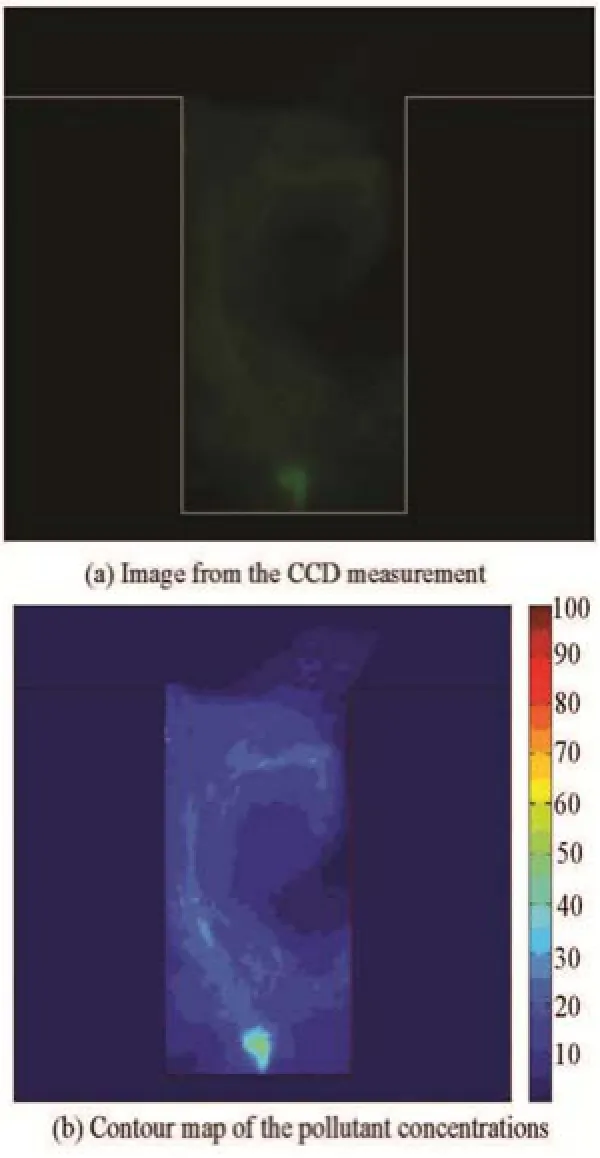
Fig.10 (Color online) Pollutant distribution on the central plane of the canyon in Case 5
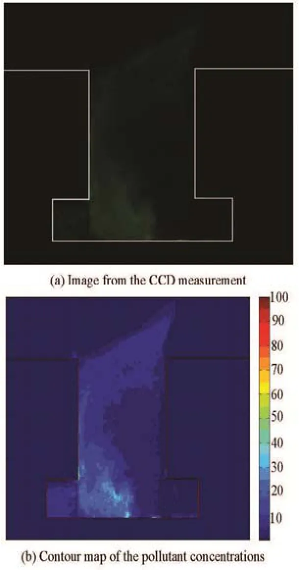
Fig.11 (Color online) Pollutant distribution on the central plane of the canyon in Case 6
The pollutant concentration on the central plane of the urban street canyon is represented in Figs.10-13, which show clearly that the pollutant distribution in an urban street canyon is influenced significantly by the three-level flat roofs. In Fig.10, it is evident that the pollutant tends to concentrate on the leeward side of the urban street canyon in Case 5. This is because a clockwise vortex is formed inside the canyon[21], which conveyed the pollutants released from the line source to the leeward side of the canyon. From Fig.11 it can be observed clearly that the pollutant is accumulated in the leeward side of the canyon in Case 6 and the pollution level in the leeward side gallery is higher than that in the windward side gallery. Obviously, the pollutant distribution pattern inside the urban canyon in Case 6 is very similar to that inside the canyon in Case 5 (this is also because a large clockwise vortex is established inside the canyon in Case 6[21]). From Figs.12 and 13, it can be observed that the pollutants are accumulated in the lower windward side and the upper leeward side of the urban street canyon and that the pollution level in the windward side gallery is higher significantly than that in the leeward side gallery for each of Cases 7 and 8. This can be explained by the two-vortex structures in the canyon[21], i.e., by a lower counter-clockwise vortex which carries the pollutants emitted from the line source towards the lower windward side of the canyon and by an upper clockwise vortex which conveys the pollutants escaped from the lower part of the canyon towards the upper leeward side of the canyon.
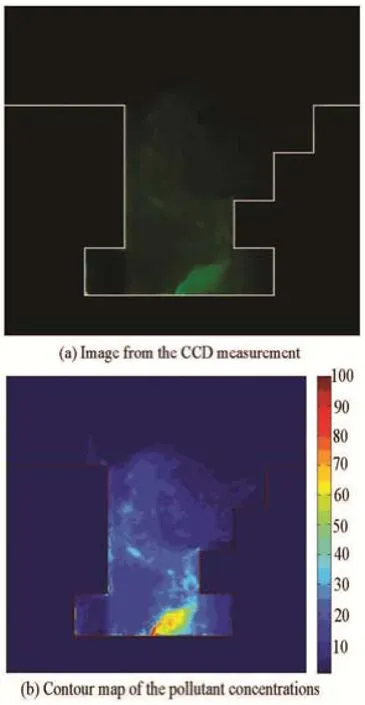
Fig.12 (Color online) Pollutant distribution on the central plane of the canyon in Case 7

Fig.13 (Color online) Pollutant distribution on the central plane of the canyon in Case 8
Comparing Fig.6 with Fig.10, and Fig.7 with Fig.11, it is seen that within a symmetrical street canyon formed by flat-roof shaped buildings with/ without galleries of an aspect ratio of 0.5 the pollutant distribution pattern for an urban environment is quite different from that for an open-country configuration(isolated environment). This difference in the pollutant distribution pattern may be explained by the formation of a massive flow separation when the wind passes through the upwind building of an isolated street canyon. When the wind passes through the upwind building of an isolated canyon in each of Cases 1 and 2, a large clockwise vortex is developed above the building roofs due to occurrence of the massive flow separation, which induces a counter-clockwise vortex inside the isolated canyon. However, the flow separation is not established above the building roofs when the wind passes through the upwind building of an urban canyon and thus only a clockwise vortex is developed within the canyon in each of Cases 5 and 6.
Comparing Fig.8 with Fig.12, it is observed that in the lower part of the canyon formed by the flat-roof upwind building and the three-level flat-roof downwind building the pollutant dispersion pattern for an urban environment is similar to that for an isolated environment. This can be explained by the formation of a two-vortex structure in the street canyon for both the urban and isolated environments. Comparing Fig.9 with Fig.13, it is also observed that in the lower part of the canyon formed by three-level flat-roof buildings the pollutant dispersion pattern for an urban environment is similar to that for an isolated environment.

Fig.14 (Color online) Pollutant distribution on the central plane of the canyon in Case 9
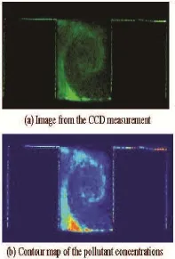
Fig.15 (Color online) Pollutant distribution on the central plane of the canyon in Case 10

Fig.16 (Color online) Pollutant distribution on the central plane of the canyon in Case 11

Fig.17 (Color online) Pollutant distribution on the central planeof the canyon in Case 12
The pollutant concentrations on the central plane of the urban street canyon in each of Cases 9-12 are shown in Figs.14-17, which reveal clearly that the wedge-shaped roof has a significant impact on the pollutant distribution pattern within an urban street canyon. From Fig.14, it can be seen that the pollutant is accumulated in the leeward side of the urban canyon formed by the flat-roof buildings. This is because a large clockwise vortex is developed inside the canyon[16]. For an urban canyon with the upward wedgeflat roof combination, the pollutants are accumulated in the lower windward side and the upper leeward side of the canyon (Fig.15). This may be explained by the formation of a two-vortex flow structure (i.e., a lower counter-clockwise vortex and an upper clockwise vortex) inside the canyon[16]. For each of the downward wedge-flat and downward wedge-downward wedge roof combination cases, the pollutant is accumulated in the leeward side of the canyon (Figs.16 and 17). This is because only one clockwise vortex is produced in the canyon[16]. From Fig.17, it can also be observed that there are pollutants distributed above the wedgeshaped roof of the upstream building. This may be due to the fact that the clockwise vortex is elongated towards the wedge-shaped roof of the upstream building[16]. The above pollutant distribution patterns inside the four urban street canyons with different roof shape combinations at an aspect ratio of 1.0 confirm the previous findings of Huang et al.[16].
3. Conclusions
The pollutant dispersion patterns within street canyons are investigated by means of experiments conducted in the environmental wind tunnel at the School of Environment and Architecture, University of Shanghai for Science and Technology.
Four different street canyon configurations with an aspect ratio of 0.5 are adopted. These include a canyon formed by two flat-roof shaped buildings without gallery, a canyon formed by two flat-roof shaped buildings with galleries, a canyon constructed by a flat-roof shaped upstream building with a gallery and a three-level flat-roof shaped downstream building with a gallery, and a canyon formed by three-level flat-roof shaped upstream and downstream buildings with galleries. Two types of canyons are utilized for the street canyon with an aspect ratio of 0.5: isolated street canyon and urban street canyon. In the isolated street canyon cases, there are no additional buildings situated upstream and downstream the street canyon. In the urban street canyon cases, four buildings are placed upstream the street canyon and three buildings are situated downstream the canyon.
品种在猕猴桃生产种植中也是具有战略地位的生产力要素,成功的种植莫不是得益于优良品种的助力。相反的,国内在猕猴桃种植选种中,惨痛教训数不胜数,究其原因,就是过于相信炒种者忽悠,缺少对品种在种植过程重要意义的评估。创新要提倡,谨慎更重要。选择品种,除了关注其出身来源(培育者及种质源),实地了解该品种全面的性状或少量试种亲自观察品种特性都是必不可少的环节。
In addition, four different urban street canyons with an aspect ratio of 1.0 are applied. These include a canyon with a flat-flat roof combination, a canyon with an upward wedge-flat roof combination, a canyon with a downward wedge-flat roof combination and a canyon with a downward wedge-downward wedge roof combination.
In the experiments the light scattering technique is used to determine the pollutant distributions inside the street canyons. From the pollutant distribution patterns measured, the effect of the street canyon configuration on the pollutant dispersion inside a street canyon with an aspect ratio of 0.5 is revealed:
(1) Isolated street canyon cases
For each of the four isolated street canyon cases,the pollutants are accumulated in the windward side of the canyon. The pollutant concentrations in the windward side gallery are significantly higher than those in the leeward side gallery for the canyons containing galleries. The range of pollutant dispersion inside the canyon formed by the three-level flat-roof shaped upstream and downstream buildings with galleries is smaller than that within the canyon formed by flatroof shaped buildings with or without galleries.
(2) Urban street canyon cases
The pollutant distribution pattern within an urban street canyon is influenced significantly by the threelevel flat roofs. The pollutant tends to concentrate on the leeward side of the urban street canyon formed by flat-roof shaped buildings with or without galleries. Whereas, for the street canyon constructed by a flatroofed upstream building with a gallery and a threelevel flat-roofed downstream building with a gallery and for the canyon formed by three-level flat-roofed upstream and downstream buildings with galleries, the pollutants are accumulated in the lower windward side and the upper leeward side of the urban canyon.
From the pollutant distribution patterns measured,it is revealed that the wedge-shaped roof has a significant impact on the pollutant dispersion inside an urban street canyon with an aspect ratio of 1.0. For theurban street canyons with flat-flat, downward wedgeflat and downward wedge-downward wedge roof combinations, the pollutants are accumulated in the leeward side of the canyon. However, the pollutants are concentrated in the windward side of the canyon with the upward wedge-flat roof combination.
[1]VARDOULAKIS S., FISHER B. E. A. and PERICLEOUS K. et al. Modelling air quality in street canyons: A review[J]. Atmospheric Environment, 2003, 37(2): 155-182.
[2]HUANG Y., LONG C. and DENG J. et al. Impacts of upstream building width and upwind building arrangements on airflow and pollutant dispersion in a street canyon[J]. Environmental Forensics, 2014, 15(1): 25-36.
[3]YASSIN M. F. Impact of height and shape of building roof on air quality in urban street canyons[J]. Atmospheric Environment, 2011, 45(29): 5220-5229.
[4]ASSIMAKOPOULOS V. D., APSIMON H. M. and MOUSSIOPOULOS N. A numerical study of atmospheric pollutant dispersion in different two-dimensional street canyon configurations[J]. Atmospheric Environment,2003, 37(29): 4037-4049.
[5]NAZRIDOUST K., AHMADI G. Airflow and pollutant transport in street canyons[J]. Journal of Wind Engineering and Industrial Aerodynamics, 2006, 94(6): 491-522.
[6]KIM J. J., BAIL J. J. A numerical study of the effects of ambient wind direction on flow and dispersion in urban street canyons using the RNG -kε turbulence model[J]. Atmospheric Environment, 2004, 38(19): 3039-3048.
[7]YASSIN M. F., OHBA M. Experimental study of the impact of structural geometry and wind direction on vehicle emissions in urban environment[J]. Transportation Research Part D: Transport and Environment, 2012,17(2): 161-168.
[8]ALLEGRINI J., DORER V. and CARMELIET J. Wind tunnel measurements of buoyantflows in street canyons[J]. Building and Environment, 2013, 59(328): 315-326.
[9]XIE X., HUANG Z. and WANG J. et al. Thermal effects on vehicle emission dispersion in an urban street canyon[J]. Transportation Research Part D: Transport and Environment, 2005, 10(3): 197-212.
[10] ZHU Zhong-wei, XIE Xiao-min and HUANG Zhen. Numerical investigation of reactive pollutant dispersion in an urban street canyon with bottom heating due to solar radiation[J]. Chinese Journal of Hydrodynamics, 2013,28(2): 159-166(in Chinese).
[11] SOLAZZO E., CAI X. M. and VARDOULAKIS S. Modelling wind flow and vehicle-induced turbulence in urban streets[J]. Atmospheric Environment, 2008, 42(20): 4918-4931.
[12] AHMAD K., KHARE M. and CHAUDHRY K. K. Model vehicle movement system in wind tunnels for exhaust dispersion studies under various urban street configurations[J]. Journal of Wind Engineering and Industrial Aerodynamics, 2002, 90(9): 1051-1064.
[13] HU Xing-jun, QIN Peng and LIAO Lei et al. Numerical simulation of the aerodynamic characteristics of heavyduty tracks through viaduct in crosswind[J]. Journal of Hydrodynamics, 2014, 26(3): 394-399.
[14] CAO J., TAMURA Y. and YOSHIDA A. Wind pressures on multi-level flat roofs of medium rise buildings[J]. Journal of Wind Engineering and Industrial Aerodynamics, 2012, 103(1): 1-15.
[15] ALI-TOUDERT F., MAYER H. Effects of asymmetry,galleries, overhanging facades and vegetation on thermal comfort in urban street canyons[J]. Solar Energy, 2007,81(6): 742-754.
[16] HUANG Y., HU X. and ZENG N. Impact of wedgeshaped roofs on airflow and pollutant dispersion inside urban street canyons[J]. Building and Environment,2009, 44(12): 2335-2347.
[17] HUANG Y. D., HE W. R. and KIM C. N. Impacts of shape and height of upstream roof on airflow and pollutant dispersion inside an urban street canyon[J]. Environmental Science and Pollution Research, 2014, 22(3): 2117-2137.
[18] ZHAN Yong, JIANG Pei and FU Cong-yu et al. Measurement system of pollutant diffusion simulation[J]. Optical Instruments, 2016, 38(2): 173-177(in Chinese).
[19] LI Song, WU Wen-quan and ZHAN Yong. Optical measurement system for instantaneous concentration fields of flows[J]. Journal of University of Shanghai for Science and Technology, 2004, 26(4): 340-347(in Chinese).
[20] SAGRADO A. P. G., BEECK J. V. and RAMBAUD P. et al. Numerical and experimental modelling of pollutant dispersion in a street canyon[J]. Journal of Wind Engineering and Industrial Aerodynamics, 2002, 90(4-5): 321-339.
[21] ZENG Ning-bin. A study on airflow and pollutant dispersion within street canyons under various building configurations[D]. Master Thesis, Shanghai, China: University of Shanghai for Science and Technology, 2010(in Chinese).
(July 6, 2015, Revised March 23, 2016)
* Project supported by the National Natural Science Foundation of China (Grant No. 51536006), the Innovation Program of Shanghai Municipal Education Commission (Grant No.10ZZ95) and the Hujiang Foundation of China (Grant No. B14003).
Biography: Yuan-dong HUANG (1964-), Male, Ph. D.,
Professor
The scattered light corresponds to the pixel intensity of the images for the CCD camera measurements. The intensity of the scattered light can be assumed to be proportional to the smoke concentration[20]. In the present study, the image from CCD measurement is processed to obtain the contour map of the relative concentration of pollutants.
- 水动力学研究与进展 B辑的其它文章
- The 2nd Conference of Global Chinese Scholars on Hydrodynamics 2016.11.11~14, Wuxi
- The mechanism of flapping propulsion of an underwater glider*
- A new design of ski-jump-step spillway*
- A water quality model applied for the rivers into the Qinhuangdao coastal water in the Bohai Sea, China*
- The numerical and experimental investigations of the near wake behind a modified square stay-cable*
- The hydraulic characteristics of end-dump closure with the assistance of backwater-sill in diversion channel*

