Analysis of swirling flow eff ects on the characteristics of unsteady hot-streak migration
Wang Jingyu,Ge Ning,Sheng Chunhua
aNanjing University of Aeronautics and Astronautics,Nanjing 210016,China
bSun Yat-Sen University,Guangzhou 510275,China
cThe University of Toledo,OH 43606,USA
Analysis of swirling flow eff ects on the characteristics of unsteady hot-streak migration
Wang Jingyua,b,Ge Ninga,*,Sheng Chunhuac
aNanjing University of Aeronautics and Astronautics,Nanjing 210016,China
bSun Yat-Sen University,Guangzhou 510275,China
cThe University of Toledo,OH 43606,USA
The temperature of flow at the combustor exit is inherently non-uniform and the hot fluid is called hot-streak.An in-house CFD software,NUAA-Turbo,was used to carry out 3D unsteady simulations on the PW-E3single-stage high-pressure turbine.The hot-streak effect based on real stator and combustor counts was approximately evaluated by the contraction/dilatation method on the interface.The unsteady attenuation and migration process of hot-streaks in the turbine passage were well captured.The general performance parameters for different circumferential positions of hot-streaks were relatively consistent.Then,the in fluences of hot-streaks on blade surface temperature were investigated by comparing results under hot-streak and uniform in flow conditions.Unsteady simulations with combined inlet hot-streak and swirling flow show that the core of a hot-streak migrates to the tip under the in fluence of a positive swirl,while the phenomenon is just opposite with a negative swirl.Therefore,the heat transfer environment of rotor blades shows great differences with different directions of inlet swirl.
1.Introduction
In an attempt to increase the engine performance,it is common nowadays for a combustor to be designed with a concept of high exit temperature and relatively low end walls temperature for cooling needed.Therefore,there exists an apparent temperature non-uniformity region at the combustor outlet,and the local hot fluid is called hot-streak.For the improvement of combustion performance,the swirl design method is adopted to enhance the fuel-air mixing and to aid the flame stability,which leads to the inlet velocity distortion.Hence,an incoming flow consisting of both hot-streak and swirl at the turbine inlet will affect its performance accordingly.In view of the above,taking into consideration the effects of both hot-streak and swirl at the primary design stage will assuredly increase the accuracy of aerodynamic and cooling design.
Numerous works focusing on hot-streak only have been investigated from the 1980s.In the experimental aspect,with an adjustable distortion generator,Barringer et al.1studied the effects of temperature non-uniformity and pressure distor-tion on the secondary flow and heat transfer,respectively.Their unsteady flow measurements showed that the radial migration ofthehot-streak alongthepressuresurface increased the thermal loading in the clearance region,and that the interaction between the hot-streak and the secondary flow made the mechanism of heat transfer and the flow field near the end walls complicated sufficiently,which have been verified by Jenny2who used fast response probes to investigate the hotstreak in an axial flow turbomachinery.In the computational aspect,most of works with three-dimensional(3D)unsteady numerical simulations concentrated on the effect of the nonuniform inlet temperature distribution on the flow field and heat transfer problems in a single-stage turbine.Zilli et al.3concluded that the turbine performance was not sensitive to non-uniform inlet temperature profiles though a small reduction in efficiency,whereas this drop in efficiency could be reduced by clocking the hot streaks toward the stators.Simone et al.4noted that the impact of the hot-streak on heat transfer for blades and casing depended on the circumferential position of the hot-streak,the ratio of hot-streak/stator count,and the ratio of cool/hot flow temperature.In another study,Basol et al.5used a particle tracking tool inconjunction with time resolved simulations to investigate the hot streak migration pattern to the tip leakage flow.Their results showed that hot streak induced secondary flows increased the radial spread of hot gas on the rotor pressure side without affecting the radial temperature distribution on the suction side.More recently,Liu et al.6studied the effect of the clearance height on the characteristics of hot-streak migration in that region,and the analysis indicated that a higher clearance height meant more leakage flows,which enhanced the migration of hot-streak and heat transfer as well.Rahim et al.7firstly investigated the effect of nozzle guide vane(NGV)lean on high-pressure turbine(HPT)aerothermal performance by comparing a nominal vane with a compound leaned vane under uniform and hot-streak inlet conditions.Rahim et al.7found that when a hot-streak was introduced,a leaned NGV resulted in a benef icial heat transfer characteristics,particularly at the tip region,as the hot fluid movement toward the tip was blocked by the radial pressure gradient on the pressure surface.Their results also highlighted the significance of an inflow temperature profilewhen consideringtheHPT bladeshapedesign optimization.
Compared with hot-streak research,the amount of research related to the impact of swirling flow on turbine performance appears to be rather limited.In fact,both experimental and computational studies mainly focus on the influence of swirl on a combustor and its emission characteristics.For example,Li et al.8investigated the effects of different swirl configurations on the recirculation zone,velocity field,temperature distribution,flame structure,and emission characteristics.Huang et al.9numerically studied the inlet swirl effect on the flow development and combustion dynamics with a large-eddysimulation(LES)technique,and more details were achieved.The swirling flow emanating from a combustor affects many important flow parameters,such as the flow incidence angle of downstream adjacent turbine stage;the loading distribution on the nozzle guide vanes;the inlet velocity;total pressure and boundary layer profiles;the free-stream turbulence;and the secondary flow characteristics.8
The importance of the combined effects of hot-streak and swirl on turbine aerothermal performance has been realized,but their de finite in fluences and mechanisms still need to be researched.Khanal et al.10carried out a 3D unsteady simulation on the MT1 single-stage HPT in terms of combined hotstreak and swirl.Their results indicated that with the swirl’s effect,the hot-streak moved downstream and was distorted synchronously.Moreover,the cores of hot-streaks were twisted clockwise by a positive swirl and counter-clockwise by a negative swirl,respectively.Hence the effect of swirling flow on the transmission characteristics of the hot-streak was signi ficant.It should be noted that the effect of combined hot-streak and swirl was nonlinear,and thus could not be linearly superimposed.Another more recent study on the aerothermal performance of the MT1 single-stage HPT under non-uniform temperature and velocity inlet pro files was performed by Rahim et al.11A qualitative shift in the roles played by two aerodynamic parameters,i.e.,heat transfer coefficient and adiabatic wall temperature,was shown in their results.They also considered the effect of NGV shaping on controlling the impacts of non-uniform inlet traverses.The rotor heat transfer characteristics under combined hot-streak and swirl were found to be dependent on the NGV shaping.They finally noted that research on the differences under different NGV shapes and inlet conditions would contribute to combined aerodynamic and heat transfer optimizations during a design process.
In this paper,an in-house CFD software,NUAA-Turbo,was used to perform 3D unsteady simulations on the PW-E3single-stage HPT.The sinusoidal correction method for a spanwise total temperature profile was adopted to obtain an approximately actual total temperature profile.A novel method of simulating a real flow field in the inter-space between the combustor and the HPT stator was also proposed.Effects of the hot-streak migration on the rotor blade surface temperature distribution and the turbine performance were then studied by comparing the results between hot-streak and uniform inflow at different instantaneous positions.The present work finally concentrated on the combined effects of hot-streak and swirl,including the hot-streak migration process in turbine passage and its effects on the heat transfer environment.
2.Computational procedures
The NUAA-Turbo solver,which is based on a structural grid,was employed in all the computational results presented in this paper.The solver is also based on a time marching of the 3D unsteady compressible Reynolds-averaged Navier-Stokes(URANS)equations.The equations were discretized in space using a second or third order Van Leer’s MUSCL scheme12based on a finite volume method with an implicit Newton iteration scheme.The inviscid and viscid fluxes were computed with the Roe scheme and the second-order central discretization,respectively.A turbulence model has been achieved by using the standard one-equation turbulence modelof Spalart-Allmaras.13The unsteady second-order accurate dual time-stepping method14has been adopted in all runs and the phase-lag method15has been used for a periodic boundary condition and the interface between rotors and stators.
The aim of the present work was to understand and assess the effect of combined hot-streak and swirl for the highly loaded PW-E3single-stage HPT.Here the clearance height has been set to 0.469 mm(approximately accounting for 0.79%of the blade height),and the numbers of stators and rotors have been set to 24 and 54,respectively.
According to a detailed NASA design report,16the inlet total pressure,the total temperature,the back pressure,and the rotational speed have been set to 1324491 Pa,1633 K,270 kPa,and 13232 rad/min,respectively.Another parameter,the inlet flow angle,has been set to zero in the present work.
3.Hot-streak computation method
Almost all recent numerical studies focusing on the hot-streak have been simplified by assuming that the numbers of hotstreaks and stators are equal and that the combustor outlet temperature profiles can be specified well corresponding to an actual condition.However,the inlet temperature profile should be specified actually enough with an effort to understand and assess the mechanism of hot-streak accurately.With the above considerations,the present work is aimed at computing and analyzing the hot-streak effect at a condition with a real ratio of hot-streak/stator count,along with real combustor outlet temperature.
3.1.Inlet total temperature distribution specification
Due to the lack of experimental combustor outlet temperature data,how to specify an accurate hot-streak temperature profile is a critical problem that needs to be resolved.Fig.1 shows an inlet radial total temperature T distribution profile along spanwise position h/H of the PW-E3high-pressure turbine(HPT),16which seems to have a typical military standard temperature profile in the form of parabola.The position of peak total temperature is found to be located at 60%of the blade height.
In fact,the discrete nozzles in a combustor can cause circumferential temperature distortion at the outlet,which should be considered in the present work theoretically.We applied sinusoidal corrections to the spanwise total temperature profile mentioned above with the method of distortion generation developed by Smith,17so that the circumferential averages were the same at each position.The corrected spanwise total temperature profile is defined as
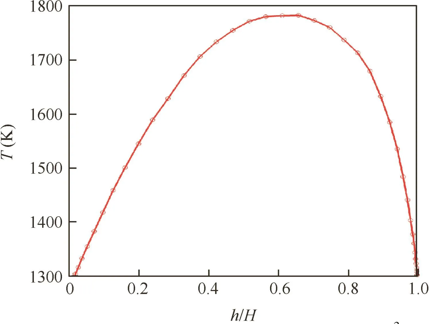
Fig.1 Radial total temperature profile at the PW-E3HPT inlet.16

where N represents the number of hot-streaks.Tavmax(z)and Twall(z)represent the peak total temperature and end walls temperature,respectively.T0is the average temperature at the combustor outlet.It is also noted that the term within the square brackets varies from zero at the inlet walls to unity at the peak average temperature.The initial phase φ0can be varied to modulate the circumferential locations of hotstreaks.
The created temperature distribution of hot-streaks with the above method is shown in Fig.2 in full and single combustor outlet views,respectively.From Fig.2 one can see that the number of hot-streaks is 30 corresponding to the number of combustor nozzles.The position of the peak total temperature(approximately 1920 K)is located in the center of each hotstreak,while the lowest total temperature(approximately 1300 K)location is at the hub surface.In terms of the variability of temperature gradient,for a given spanwise position,the circumferential gradient varies most and decreases gradually from that position to end walls,where the temperature is low and the iso-lines are smooth.All these specifications are consistent with the real temperature distribution conditions regarding the cooling system.
3.2.Contraction/dilatation method
A method of simulating a real flow field in the inter-space between a combustor and a HPT stator is proposed to deal with the computational problems caused by the disagreement between hot-streak and stator counts.The combustor-NGV interface is then resolved with the contraction/dilatation method proposed by ONERA,18which aims at performing unsteady simulations in a contractive computational domain with the prerequisite of the same geometrical models.This method is illustrated in Fig.3,where A1and A2represent the combustor outlet and the NGV inlet,respectively.Given that the numbers of combustors and NGVs are Ncand Nsrespectively,the passage angles of a single combustor and stator can be obtained as

The inter-space passage angle Ecis assumed to be the average of these two values,i.e.

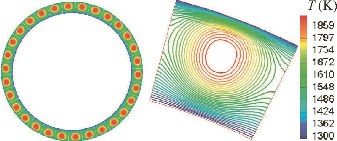
Fig.2 The total temperature distribution at the combustor outlet.
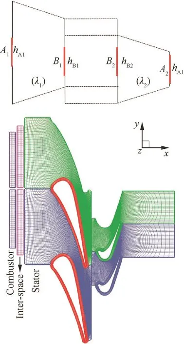
Fig.3 Principle of contraction/dilatation method(top)and computational domain(bottom).
Then we can obtain

The combustor outlet boundary length is later amplified or contracted λ1times of the initial value.After this,aerodynamic parameters at boundaries B1and B2can be specified by boundaries A1and A2at the same axial position,respectively.Hence,boundaries B1and B2have the same circumferential scale Edand periodic boundary conditions can be adopted to ensure the mass flow continuity.This method of interface contraction/dilatation depends ultimately on the parameters λ1and λ2,which reflect the accuracy of periodic approximation for the interface to a certain extent.What is also shown in Fig.3 is a schematic diagram of a computational domain with two added domains,representing the combustor and the interspace respectively.These two domains were computed solely,and the data at the interface could be transmitted to each other with the contraction/dilatation method.The most valuable advantage of this method is enabling us to carry out unsteady simulations with a real ratio of hot-streak to stator count.
3.3.Equivalent hot-streak
Theoretically,the hot-streak count in a turbine passage should be consistent with that of combustor nozzles.Note that the total temperature distribution should be specified as discussed above.When entering a stator passage,the hot-streaks change their sizes,and their count becomes the same as that of stators for the contraction/dilatation method,which brings a certain difference between this condition and an actual one.This can be resolved by assuming that the percentage that the hot-streaks are accounting for in a turbine passage is identical with that at the combustor outlet in terms of area,and supposing that the effects of the hot-streaks in this condition on turbine aerothermal performance are the same as those in a real condition,which is defined as equivalent hot-streak.Fig.4 shows the passage-aligned and vane-aligned total temperature distributions.It should be noted that the variations of these two time-averaged hot-streak configurations are similar.The hot-streak at the stator inlet is stretched in the circumferential direction,while unaltered in the spanwise direction.There exist area correlations before and after contraction/dilatation as described below:

and then the periodic boundary condition in inter-space can ensure

When computation converged,the hot-streak area ratios of these two cross sections were calculated and both results were 0.514.Therefore,the hot-streak evaluated with the contraction/dilatation method is considered to be consistent with that in actual conditions.Simultaneously this method matches well with the phase-lag method used at the interface.However,the effect of the circumferential hot-streak position variation on turbine cycle performance still needs to be verified experimentally.
4.Results and discussion
4.1.Hot-streak clocking effect
The effects of both time-averaged hot-streak types(shown in Fig.4)on turbine performance were evaluated with unsteady numerical simulations,and the results along with those of uniform inflow cases are shown in Table 1 for comparison.The mass flow rate and total pressure ratio in both cases are found to be consistent,while the stage efficiency in the hot-streak cases drops approximately 1.5%compared with those of the uniform inflow cases.With the effects of hot-streaks,the entropy increases while the secondary flow strengthens in turbine passages,and consequently the efficiency decreases.19The stage performance agreement between two different spatial positions illustrates that the turbine performance is not sensitive to the circumferential positions of hot-streaks.
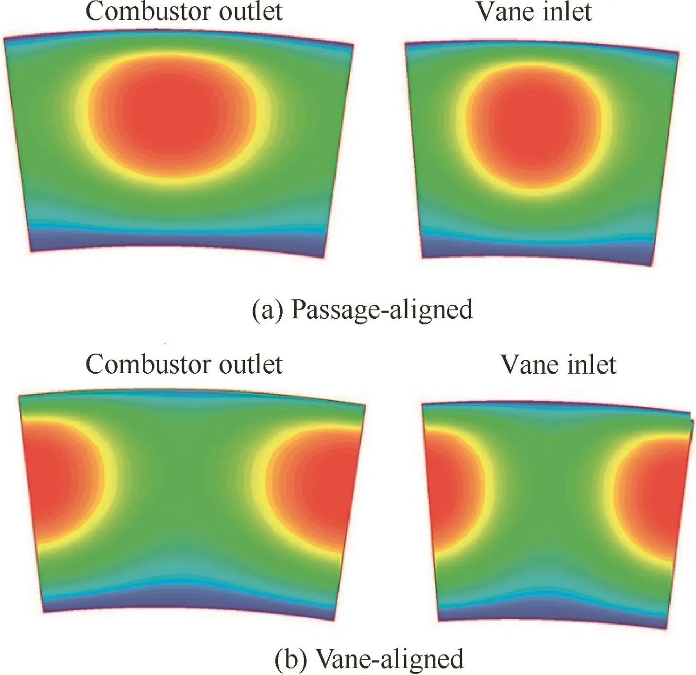
Fig.4 Passage-aligned and vane-aligned total temperature distributions.

Table 1 Time-averaged results’comparison for three cases.
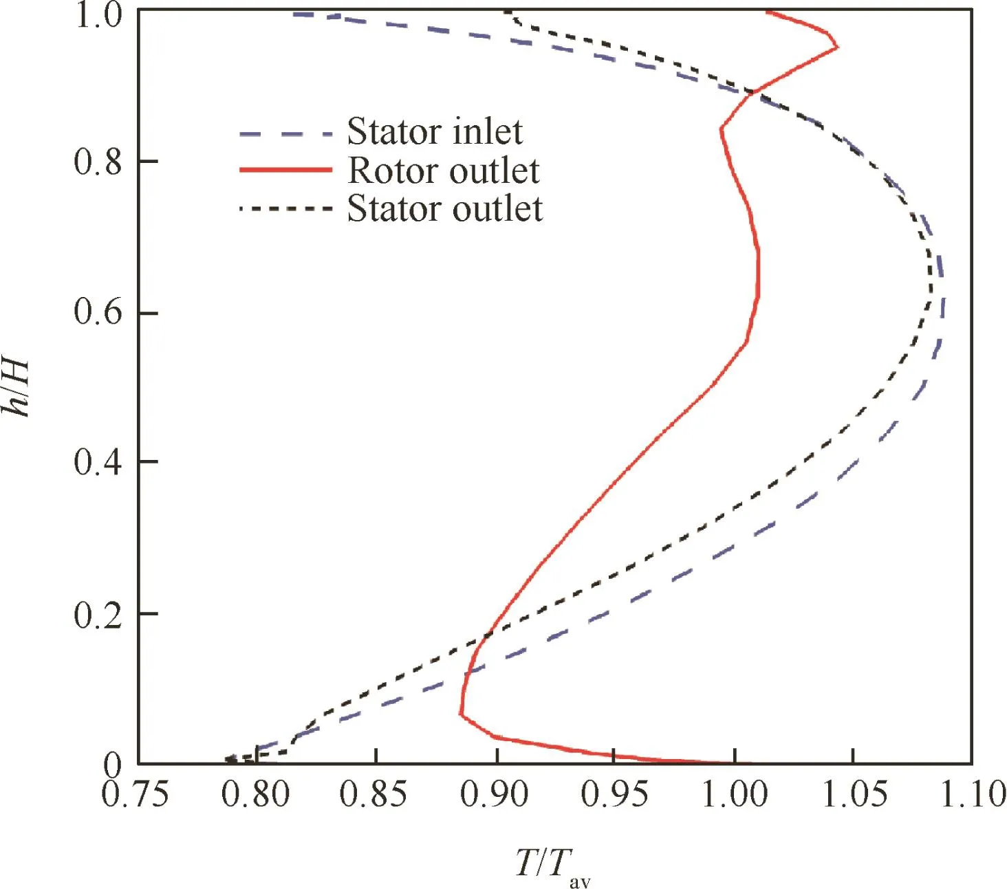
Fig.5 Radial total temperature distortion.
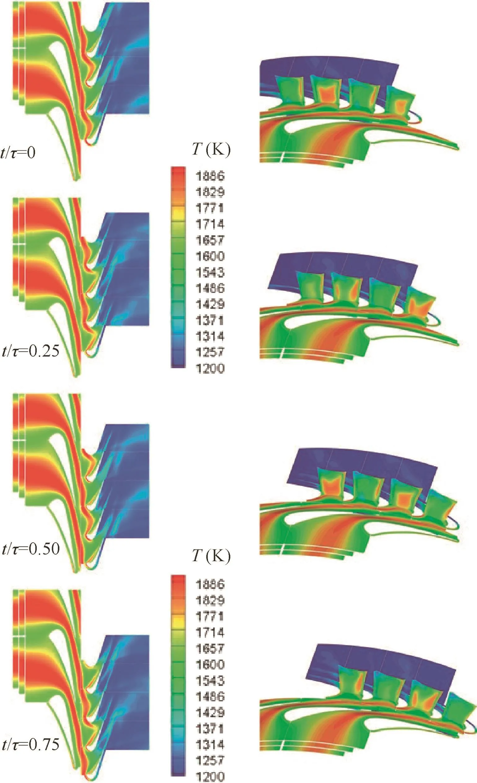
Fig.6 Unsteady migration of the hot-streak.
4.2.Unsteady migrations of hot-streaks
It is clear that both stators and rotors in a HPT bear high thermal loading,and thus thermal protection needs to be well designed.However,unsteady migrations occur when hotstreaks pass through a turbine passage with the effects of pressure gradient and complicated secondary flow.When hot fluids get together,the heat transfer characteristics on the blade surface change.One purpose of the present work is to study the unsteady migrations of hot-streaks.The results of total temperature distribution at three specified sections,i.e.,the stator inlet,the stator outlet,and the rotor outlet,are shown in Fig.5.Hot-streaks are not weakened and the radial locations of their cores are unchanged when passing through the stator passage,whereas they decay rapidly and the radial amplitude of the total temperature distortion varies within 10%at the rotor outlet.The position of the peak total temperature is located at the tip,rather than the 60%of the blade height for the stator inlet.
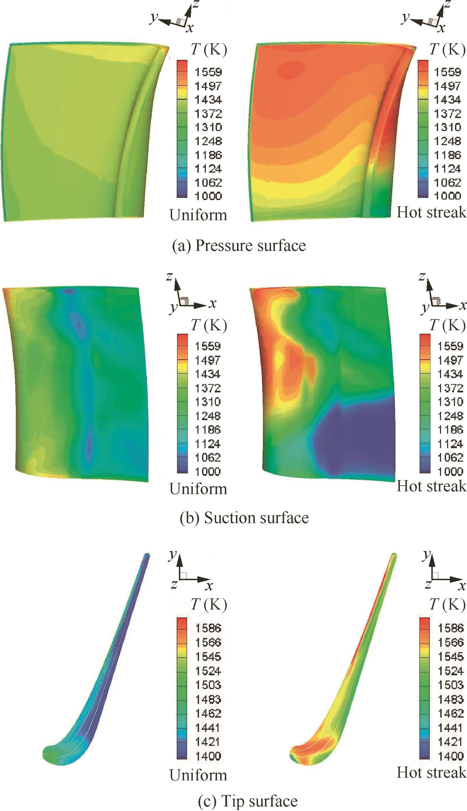
Fig.7 Uniform inflow and hot-streak inflow for pressure,suction and tip surfaces.
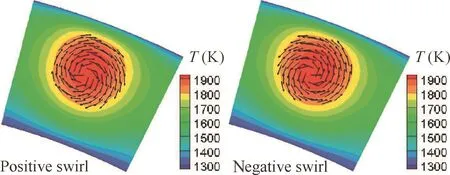
Fig.8 Velocity fields for positive and negative swirls.
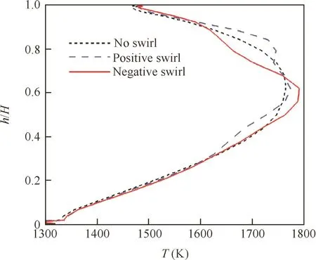
Fig.9 Radial total temperature distribution at stator outlet.
The unsteady migrations of hot-streaks in terms of total temperature T at four different instantaneous times(at time t/τ=0.0,0.25,0.5 and 0.75 respectively,where τ is the rotor blade passing period.)are clearly observed in Fig.6 for the blade mid-span section and the section at 30%axial chord of the rotor blade.The hot-streak areas are found to be altered at the inlets of the combustor and the stator,but the area percentage they account for in all annulus passages keeps constant,which agrees well with the proposition of equivalent hot-streak.
When hot-streaks enter the stator passage,they tend to shrink and become stripe-shaped at the outlet.These hotstreaks are then incised by the rotor leading edge and stretched into the shape of a ‘bow”,as there exists an apparent velocity difference between the suction and the pressure surface.After that,these hot-streaks decay rapidly as a result of the total temperature decrease,and their mixing with downstream flow.The hot-streaks have a characteristic of positive jet flow,and they tend to be assembled near the pressure surface in the turbine blade passage,resulting in a cool/hot fluid segregation phenomenon,which is called Kerrebrock effect.20Moreover,the hot fluid migrating to the tip region as a result of the radial pressure gradient is also clearly observed in Fig.6,which can explain why the peak total temperature occurs in the tip region at the rotor outlet as shown in Fig.5.
4.3.Effects of hot-streaks on turbine blade temperature field
The comparisons of rotor blade temperature between uniform and hot-streak cases are presented in Fig.7(a)and(b).Due to the effects of hot-streak migration and transport,the differences between both cases are obvious.With uniform inflow,the temperature distribution on the pressure surface is wellproportioned and the peak temperature exists at the stagnation point.In contrast with hot-streak,almost the whole pressure surface is flooded with high-temperature flow,particularly near the blade tip.A high-temperature region lies between the leading edge and the position of 30%axial chord on the suction surface,while the hub is flooded with cool fluid because of the Kerrebrock effect.20The impacts of hotstreaks on the temperature field on the blade tip surface are also obvious in Fig.7(c).On the whole,the temperature on the blade tip surface with hot-streaks is found to be much higher,which corresponds well to the migrations of hotstreaks to the pressure surface and the blade tip region.The unsteady migrations of hot-streaks increase the thermal loading on the blade substantially,and thus the hot-streak effect needs to be treated seriously.
4.4.Combination of hot-streak and swirl effects
Actually,both the temperature and velocity distortions exist at the combustor outlet.For an advanced combustor,the tendency to decrease the dimension increases the importance of research on swirling flow effect.The clockwise and counterclockwise swirling flows(looking upstream,here defined as positive and negative swirls,respectively)at the stator inlet were generated with a numerical method to evaluate the effect of swirling flow on the hot-streak migration.The stator inlet velocity fields for both types of swirling flow are presented in Fig.8.The amplitudes of velocity distortions were set to 0.1 times of the local axial velocity,and the centers of both swirl and hot-streak were superimposed.
In this case,the contraction/dilatation method discussed above was also adopted to carry out unsteady simulations for the PW-E3HPT,and analyses were performed to understand the aerothermal behavior of the hot-streak under the influence of a positive or negative swirl.

Fig.10 Iso-surfaces of total temperature.

Fig.11 Temperature field on pressure,suction and tip surfaces.
The radial total temperature distribution at the stator outlet varying distinctly with swirling flow is observed in Fig.9.Isosurfaces of the total temperature along with the surface streamlines for the migrations of hot-streaks are shown in Figs.10 and 11.It is clear that a hot-streak,when combined with a swirling flow,undergoes twisting as it moves downstream.A negative swirl is found to twist the core of the hot-streak counter-clockwise and transport the hot fluid to the hub region.Meanwhile,the core of the hot-streak moves slightly toward the tip region under the influence of a positive swirl.
5.Conclusions
An agreement between the actual total temperature profile and the radial temperature distribution modulated with the method of sinusoidal correction has been achieved.The contraction/dilatation method proposed by ONERA18has been adopted to resolve the problem of disagreement between hot-streak and statorcounts.The resultsofunsteady numerical simulations on combined hot-streak and swirling flow for the PW-E3HPT are analyzed in this paper,and some general observations can be summarized from the comparisons.
(1)The equivalent hot-streak,in good agreement with the actual combustor exit temperature distribution,can be obtained with the contraction/dilatation method.Also with this method,unsteady simulations on a single passage can be performed,which contributes to saving computational costs.
(2)The turbine efficiency decreases with the hot-streak effect.The aerodynamic parameters are found to be almost unchanged for the hot-streak clocking effect,and its impact on heat transfer characteristics still needs more research.
(3)When entering the stator passage,the hot-streak is incised by the rotor leading edge and decays rapidly.Hot fluid is also observed to assemble near the pressure surface and then is transported toward the tip region.
(4)When combined with the swirling flow,the hot-streak is twisted and moves to the tip or hub region for a positive or negative swirl,respectively.Particularly for the latter case,the temperatures at the leading edge,on the pressure surface,and in the blade tip region are apparently low,which enables designers to improve the heat environment by changing the swirl rotational direction properly.
Acknowledgements
This paper was supported by the AECC Shenyang Engine Research Institute of China.
1.Barringer MD,Thole KA,Polanka MD.Developing a combustor simulator for investigating high pressure turbine aerodynamics and heat transfer.In:ASME turbo expo 2004:power for land,sea,and air.Vienna:American Society of Mechanical Engineers;2004.p.565–75.
2.Jenny P,Lenherr C,Abhari RS,Kalfas A.Effect of hot streak migration on unsteady blade row interaction in an axial turbine.J Turbomach 2012;134(5):051020.
3.Zilli A,Pachidis V,Jackson A,Pilidis P.CFD investigation of the performance of a military HP axial turbine subjected to inlet temperature distortionASME turbo expo 2005:power for land,sea,and air.Reno:American Society of Mechanical Engineers;2005.p.1107–16.
4.Simone S,Montomoli F,Martelli F,Chana K,Qureshi I,Povey T.Analysis on the effect of a nonuniform inlet profile on heat transfer and fluid flow in turbine stages.J Turbomach 2012;134(1):2657–70.
5.Basol AM,Jenny P,Ibrahim M,Kalfas A,Abhari R.Hot streak migration in a turbine stage:integrated design to improve aerothermal performance.J Eng Gas Turbines Power 2010;133(6):847–60.
6.Liu Z,Liu Z,Feng Z.Unsteady analysis on the effects of tip clearance height on hot streak migration across rotor blade tip clearance.J Eng Gas Turbines Power 2014;136(8):082605.
7.Rahim A,Khanal B,He L,Romero E.Effect of NGV lean under influence of inlet temperature traverse.J Turbomach 2014;136(7):68–75.
8.Li G,Gutmark EJ.Effects of swirler configurations on flow structures and combustion characteristicsASME turbo expo 2004:power for land,sea,and air.Vienna:American Society of Mechanical Engineers;2004.p.423–33.
9.Huang Y,Yang V.Effect of swirl on combustion dynamics in a lean-premixed swirl-stabilized combustor.Proc Combust Inst 2005;30(2):1775–82.
10.Khanal B,He L,Northall J,Adami P.Analysis of radial migration of hot-streak in swirling flow through high-pressure turbine stage.J Turbomach 2013;135(4):041005.
11.Rahim A,He L.Rotor blade heat transfer of high pressure turbine stage under inlet hot-streak and swirl.J Eng Gas Turbines Power 2015;137(6):062601.
12.Anderson WK,Thomas JL,Van Leer B.Comparison offinite volume flux vector splitting for Euler equations.AIAA J 1986;20(9):1453–60.
13.Spalart PR,Allmaras SR.A one equation turbulence model for aerodynamic flows.La Recherche Ae´rospatiale 1992;439(1):5–21.
14.Jameson A.Time dependent calculations using multigrid,with applications to unsteady flows past airfoils and wings.Reston:AIAA;1991.Report No.:AIAA-1991-1596.
15.Erdos JI,Alzner E,McNally W.Numerical solution of periodic transonic flow through a fan stage.AIAA J 1977;15(11):1559–68.
16.Thulin RD,Howe DC,Singer ID.Energy efficient engine highpressure turbine detailed design report.Reston:NASA;1982.Report No.:NASA CR-165608.
17.Smith CI,Chang D,Tavoularis S.Effect of inlet temperature nonuniformity on high-pressure turbine performanceASME turbo expo 2010:power for land,sea,and air.Glasgow:American Society of Mechanical Engineers;2010.p.2465–76.
18.Fourmaux A.Evaluation of a technique for numerical calculation of viscous fluid flow in multi-stages turbomachinery31eme Colloque d’Aerodynamique Appliquee.Paris:Ministere de l’Enseignement Superieur;1995[French].
19.Qiao J.Investigation on aerodynamic optimization design and hot streak effects in counter-rotating turbine[dissertation].Beijing:Graduate University of Chinese Academy of Sciences;2012[Chinese].
20.Kerrebrock JL,Mikolajczak A.Intra-stator transport of rotor wakes and its effect on compressor performance.J Eng Power 1970;92(4):359–68.
Ge Ning is a full professor and Ph.D.supervisor in the College of Energyamp;Power Engineering at Nanjing University of Aeronautics and Astronautics(NUAA).He received the Ph.D.degree from University of Douai Engineer in France in 1993.With decades of efforts,he has gained a good reputation in the research field of aeroengine in China.Currently,his main research interests cover computational fluid dynamic(CFD)in turbomachinery,and overall performance prediction and design of aero-engine.
28 July 2015;revised 10 February 2016;accepted 7 August 2016
Available online 20 October 2016
High pressure turbine;
Hot-streak;
Interface contraction/dilatation;
Swirling flow;
Unsteady flow
Ⓒ2016 Chinese Society of Aeronautics and Astronautics.Production and hosting by Elsevier Ltd.This is anopenaccessarticleundertheCCBY-NC-NDlicense(http://creativecommons.org/licenses/by-nc-nd/4.0/).
*Corresponding author.Tel.:+86 25 88492201 2613.
E-mail address:gening@nuaa.edu.cn(N.Ge).
Peer review under responsibility of Editorial Committee of CJA.
Production and hosting by Elsevier
http://dx.doi.org/10.1016/j.cja.2016.09.001
1000-9361Ⓒ2016 Chinese Society of Aeronautics and Astronautics.Production and hosting by Elsevier Ltd.
This is an open access article under the CC BY-NC-ND license(http://creativecommons.org/licenses/by-nc-nd/4.0/).
 CHINESE JOURNAL OF AERONAUTICS2016年6期
- CHINESE JOURNAL OF AERONAUTICS的其它文章
- Implicit discontinuous Galerkin method on agglomerated high-order grids for 3D simulations
- Design and implementation of rigid-flexible coupling for a half-flexible single jack nozzle
- Dynamic simulation of aerial towed decoy system based on tension recurrence algorithm
- A quasi-one-dimensional model for hypersonic reactive flow along the stagnation streamline
- An experimental investigation on static directional stability
- Transonic wing stall of a blended flying wing common research model based on DDES method
