Wave force on composite bucket foundation of an offshore wind turbine*
Ji-jian LIAN (练继建), Tong-shun YU (于通顺),2, Jin-feng ZHANG (张金凤)
Wave force on composite bucket foundation of an offshore wind turbine*
Ji-jian LIAN (练继建)1, Tong-shun YU (于通顺)1,2, Jin-feng ZHANG (张金凤)1
1. State Key Laboratory of Hydraulic Engineering Simulation and Safety, Tianjin University, Tianjin 300072, China, Email: tju_luntan@126.com 2. College of Engineering, Ocean University of China, Qingdao 266100, China (Received February 16, 2014, Revised October 10, 2014)
A new analytical expression for calculating the wave force on a composite bucket foundation is obtained. Based on the diffraction theory, the analytical solution of the wave pressure and the wave force on the composite bucket foundation is accurately derived by assigning reasonable boundary conditions. Experiments for the wave pressure on the bucket foundation with a scale of 1:60 under different wave conditions in the wave flume are designed and conducted. The analytical results agree well with the experimental data, and the theoretical approach can accurately predict the wave force on the large-scale structures. The wave pressure distribution on the composite bucket foundation is presented and the influence of the wave height, the water depth and the wave period on the wave force on the composite bucket foundation is investigated. This study provides a quite accurate method to calculate the wave force on a composite bucket foundation, which gives a good framework for future studies of the wave force on other large-scale structures with complex boundaries.
wave force, composite bucket foundation, diffraction theory, wave flume
Introduction
Monopile, gravity-base, tripod, jacket structures and suction caisson foundations are widely used in the development of offshore wind powers[1], in which su- ction caisson foundations are introduced in the offsho- re wind power as widely used under a variety of types of soil conditions. The wind energy development sees a substantial progress in recent years, and large-scale suction caisson foundations are developed. However, the stress concentration between the foundation and the tower may restrict the promotion of the traditional suction caisson foundations. Lian et al.[2,3]and Ding et al.[4]proposed a new kind of suction caisson called composite bucket foundation. The composite bucket foundation makes full use of the advantages of the high tensile capacity of the steel strand and the high compressive capacity of the concrete, so that the large moment and horizontal loads can be transferred from the tower to the foundation by designing the prestre- ssing arc transition structure. Additionally, the compo- site bucket foundation reduces the material and const- ruction costs by 30%, and it is worth being applied and popularized in the offshore wind power develop- ment. One example of the applications is the Daoda composite bucket foundation offshore wind turbine in Jiangsu Province (as shown in Fig.1).
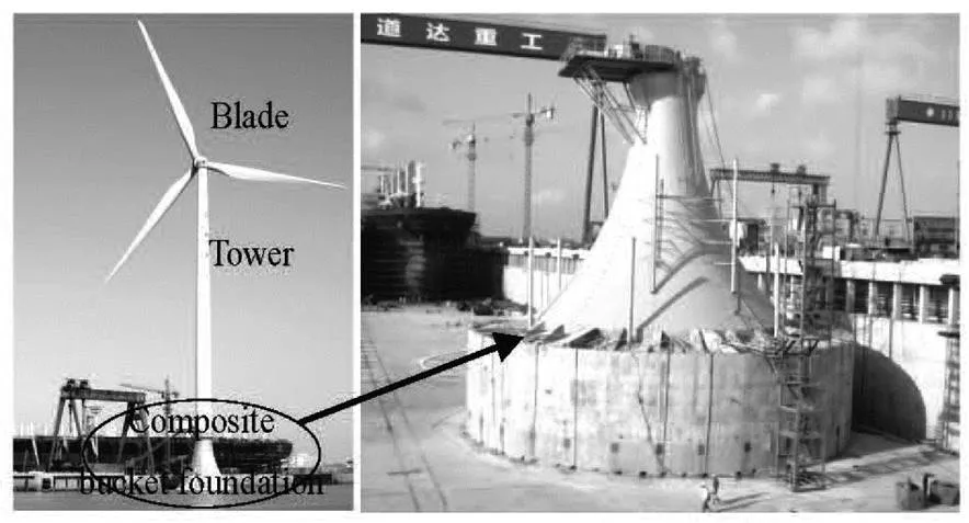
Fig.1 Schematic diagram of the composite bucket foundation and a real example
The wave force is one of the key factors in the design of the large-scale composite bucket foundation, and it has a great influence on the safety of the wind power structure. The wave motion around the compo- site bucket foundation with a complex boundary is an interesting issue in the coastal and ocean engineering, but the wave force on this new composite bucket foundation is not well studied.
The wave force calculation for a large-scale ma- rine structure when the presence of the structure affe- cts the incident wave is based on the diffraction theo- ry[5]. A train of regular surface waves is incident upon a large-scale cylinder, and the waves are partially reflected and partially transmitted. The wave field around the large-scale structure consists of two com- ponents: (1) the incident wave field and (2) the scatte- red wave field (as shown in Fig.2). It can be assumed that the structure affects the incident wave if the width of the structure is larger than one fifth of the wave length, as was verified by many experiments. The theory is different from the Morison theory[6]in which it is assumed that the diameter of the structure is smaller than one fifth of the wave length, and the presence of the structure does not affect the incident wave.
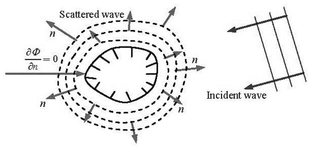
Fig.2 Wave field around large-scale marine structure
The diffraction theory is generally accepted in the wave force calculation for a large-scale structure, and it can be applied to the wave force calculation under various wave conditions. Ohl et al.[7]investiga- ted the diffraction of regular waves by arrays of verti- cal bottom-mounted circular cylinders using theoreti- cal, computational, and experimental methods. It could be seen that the linear diffraction theory is accu- rate at predicting the wave force on the large-scale st- ructure, even for waves of high steepness. Bai and Taylor[8]investigated the diffraction of nonlinear waves around a vertical circular cylinder. Song and Tao[9]derived an analytical solution of the wave force on a concentric two-cylinder system acted by a short- created incident wave based on the diffraction theory. You et al.[10]proposed an analytical method to analyze the radiation and the diffraction of waves by a bottom- mounted circular cylinder in a two-layer fluid.
In recent years, large-scale marine structures with complex shapes and boundaries[11]were developed ra- pidly, and the diffraction theory still has wide applica- bility in the wave force calculation for these marine st- ructures. Tao et al.[12]described the development of an efficient scaled boundary finite-element model for the simulation of short-crested wave interaction with the concentric porous cylindrical system. Yu and Zhang[13]derived a new analytic solution of the mild-slope long wave equation for studying the effects of bottom topo- graphy based on diffraction theory. Koo and Kim[14]investigated the hydrodynamic interaction and mecha- nical coupling effects of two floating platforms conne- cted by elastic lines. Williams and Li[15]investigated the interaction of waves with arrays of bottom-mou- nted, surface-piercing circular cylinders theoretically. A semi-analytical solution of the wave force was ob- tained by dividing the fluid domain into the exterior and the interior fluid regions. It was found that the po- rosity of the structures may result in a significant re- duction of the wave force. Shi et al.[16]carried out an investigation on the diffraction of water waves by a vertically floating cylinder in a two-layer fluid of a fi- nite depth based on the diffraction theory.
The diffraction theory is widely used in the wave force calculation of various kinds of large-scale mari- ne structures with complex boundaries. However, the wave force calculation for composite bucket founda- tions is rarely addressed in studies. Therefore, combi- ned with the diffraction theory, this paper gives the analytical expression with which an accurate calcula- tion can be made for the wave force on the composite bucket foundation.
1. Theoretical calculation of wave force on the composite bucket foundation
The composite bucket foundation in the Daoda offshore wind farm is 30 m in diameter and 6 m in depth with an arc transition of diameter of 17.89 m (as shown in Fig.3). The arc transition structure of diame- ter of decade meters, longer than one fifth of the wave length affects the incident wave significantly, so the wave force is calculated based on the diffraction theo- ry. Meanwhile the impact of the wave breaking is ig- nored in the wave force calculation.
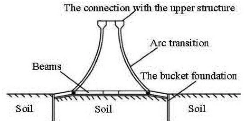
Fig.3 Vertical cross section of the foundation
1.1
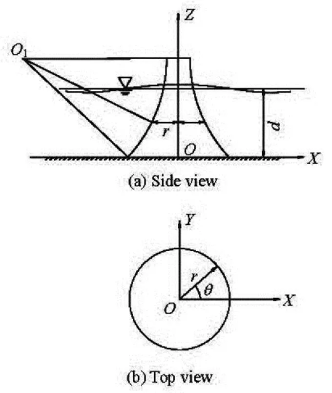
Fig.4 Definitions of arc transition of composite bucket founda- tion
Velocity potential can be expressed as
According to the small amplitude wave theory, the total velocity potential can be expressed as
With the above assumptions, the velocity poten- tialsatisfies the Laplace Equation
The free surface boundary condition
And the bottom boundary condition
The total velocity potential on the foundation can be expressed as
The scattered wave potentialis negligible at infinity, and it can be expressed as
where
1.2
The velocity potential of the incident wave can be assumed as
The Laplace Eq.(3) in the cylindrical coordinates is described as
Substituting Eq.(8) into Eqs.(6) and (9), the velo- city potential of the scattered wave is deduced as
So the velocity potential in the wave field is ex- pressed as
The arc transition surface equation of the compo- site bucket foundation (shown in Fig.4(a)) is
Substituting Eqs.(11) and (13) into Eq.(12),,,can be rendered as follows:
where
According to the small amplitude wave theory, the wave pressure can be defined as. An analytical solution can be expressed as
where
The real part of Eq.(18) is the wave pressure on the surface of the composite bucket foundation, and it is
where
The wave force of unit height on the foundation along the wave propagation direction can be expressed by integration as
where
The wave force of unit height on the foundation in the direction ofaxis is expressed as
Due to the orthogonality of trigonometric functions,.
Therefore, the wave force on the composite bu- cket foundation along the wave propagation direction is determined as
where
It can be seen from the analytical expression that the wave force on the foundations is related to the size of the arc transition and the wave conditions. A pro- gram for the wave force on the composite bucket foundation and the wave pressure on the surface of the foundation using MATLAB language is developed.
2. Experiment setup
In order to test the validation of the theoretical solutions (as presented in Section 1), an experiment is designed and conducted in a wave flume of 90 m in length, 2 m in width and 1.8 m in depth at the State Key Laboratory of Hydraulic Engineering Simulation and Safety, Tianjin University (as shown in Fig.5).
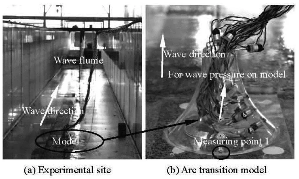
Fig.5 Experimental setup in wave flume
The wave maker is located at one end of the flume, where regular waves with given frequencies are generated. At the other end of the tank, there is an absorbing layer. The reflections from the absorbed layer amount to less than 5%. The data are synchro- nously collected with a sampling interval of 0.1 s by the data acquisition system.
The part of the composite bucket foundation sub- jected to the wave force is the arc transition, which is selected in the experimental study. The arc transition of the foundation is made of plexiglass with a thicken- ss of 0.005 m, and the model is located on the bottom 16 m away from the wave maker. In order to minimize the wall effect, the maximum diameter of the model is less than 1/7 of the width of the wave flume so that there would be a good comparability between the ex- perimental results and the theoretical analysis in an unbounded flow field. The arc transition model of the scale of 1:60 is designed and the maximum diameter and height of the model are 0.314 m and 0.235 m, re- spectively. The corresponding scaling laws in this model scale are shown in Table 1. 23 pulsating pre- ssure sensors on the arc transition (as shown in Fig.5(b)) are arranged to measure the wave pressure on the foundation, and the wave force could be obtai- ned by integration. These pulsating pressure sensors on the arc transition model are arranged in five series in,,,anddirections (the sen- sors at the waveward side is atdirection). The arrays inanddirections are arranged with four pulsating pressure sensors in the interval of 0.035 m from the bottom to the top of the arc transition, and the arrays in,anddirections are insta- lled with five pulsating pressure sensors in the interval of 0.035 m from the bottom to the top of the arc tran- sition.

Table 1 Corresponding scaling laws with a length scale of 1:60
Several cases are tested to validate the analytical results (Table 2). The wave pressure time history of the measuring Point 1 of Case 1 is shown in Fig.6(a). The noise jamming can be observed, especially in the wave crest and the wave trough, and the denoising is required before data processing. The empirical mode decomposition (EMD) method is developed for analy- zing the nonlinear and nonstationary data, as is widely used in denoising[17]. According to the EMD method, the intrinsic mode function (IMF) components of lower and higher frequencies are removed, leaving out the components of the same frequency as the wave- maker. The wave pressure time histories of measuring Point 1 before and after denoising in Case 1 are shown in Fig.6, in which all results are based on the model scale.

Table 2 Wave parameters in various cases
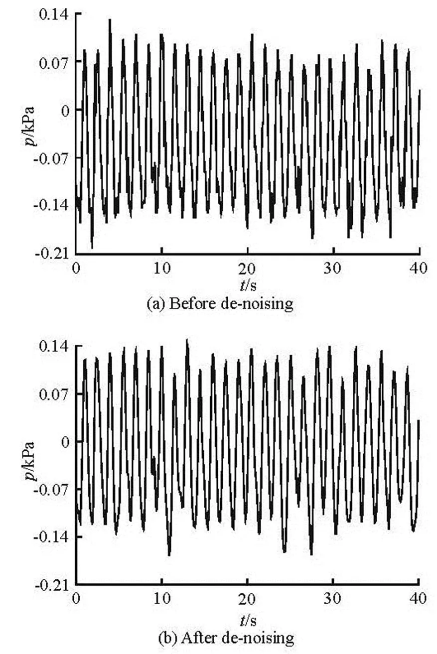
Fig.6 Comparison of wave pressure before and after denoising at the measuring Point 1 (Case 1)
3. Results and discussions
3.1
Figure 7 shows the time histories of the wave force under five wave conditions, respectively. All re- sults are converted into the prototype scale values in Fig.7 and the following figures. The wave forces ob- tained by the analytical solution based on the regular wave obey the sine or cosine laws, and the maximum wave force remains constant. However, the experime- ntal results show approximately the sine or cosine characteristics and the maximum or minimum wave forces vary slightly with time.

Fig.7 Time histories of wave forces on the foundation in different cases
We also compare the root mean squares (rms) of the wave forces obtained by the analytical solution with the experimental results for various wave numbe- rs (Fig.8), and good agreements are obtained.
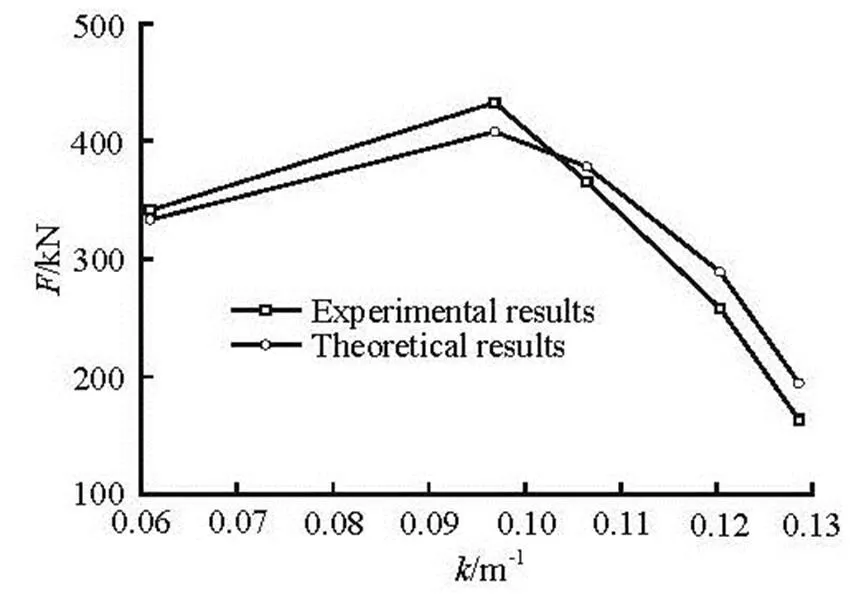
Fig.8 Comparison of theoretical and experimental results
When the water depth is 8.82 m, the wave period is 11.625 s and the wave height is 1.2 m (Case 1), the rms wave force obtained by the experiment is 341.3 kN against 333.4 kN of the theoretical solution. The relative error between the analytical results and experimental data is about 2.4%. The rms wave forces for experiment and theoretical solution in Case 2 are 431.2 kN, 407.9 kN, respectively, and the relative error is about 5.7%. The rms wave force for experime- ntal results and theoretical data in case 3 are 365.3 kN, 378.4 kN, respectively, and the difference between theory and experiment is about 3.5%. It can be seen that the analytical result is consistent with the experi- ments.
The experimental wave forces in Cases 4 and 5 are 259.0 kN and 163.6 kN, respectively. The relative error between the experimental data and the theoreti- cal results are about 9.4% and 15.1%, respectively. The relative error increases with the decrease of the water depth because of the fewer measuring sensors in the shallow water. For example, there are only ten sensors (in Eq.(23)) in Cases 4 and 5.
From the relationship between the wave number and the wave force on the foundation (Fig.8), the ex- perimental results are consistent with the analytical data. It is concluded that the diffraction theory gives an accurate calculation of the wave force on the com- posite bucket foundation. In the previous application of the composite bucket foundation, the wave force was obtained by a piecewise integration[18], in which the structure with variable cross sections along the vertical direction was divided into small vertical se- ctions and the Morison equation and the diffraction theory were applied to calculate the wave force on each section. We select the wave condition 2-C of the previous study for the wave pressure comparison be- tween the previous analytical solution and the theore- tical results presented in this study. The maximum wave pressures under water depth of 8.0 m on the foundation of different heights of 0.1 m and 5.0 m are 4.56 kPa and 7.23 kPa, respectively. The relative error is about 48.5%. It can be seen that the wave force is overestimated by the previous method of piecewise in- tegration without considering the integrity of the wave field around the composite bucket foundation. It can be concluded that the new analytical method based on the diffraction theory proposed in this paper can give much more accurate calculation results of the wave force on the composite bucket foundation than the previous method.
3.2
The wave pressure distribution on the composite bucket foundation is investigated under a certain wave condition, such as with water depth of 8 m, wave pe- riod of 7 s, and wave height of 0.7 m. Considering the symmetry of the distribution of the wave pressure on the foundation, the wave pressure distributions along the angles of,,,and(Fig.5(b)) at various times,,,andare shown in Fig.9. The wave pressure distributions at the front and rear sides of the composi- te bucket foundation at the same time are different due to the diffraction effects of the large-scale structure. And the wave pressure on the foundation also changes when the wave propagates. On the front face the hi- gher pressure is observed at, whereas on the rear side of the foundation the higher pressure occurs at.
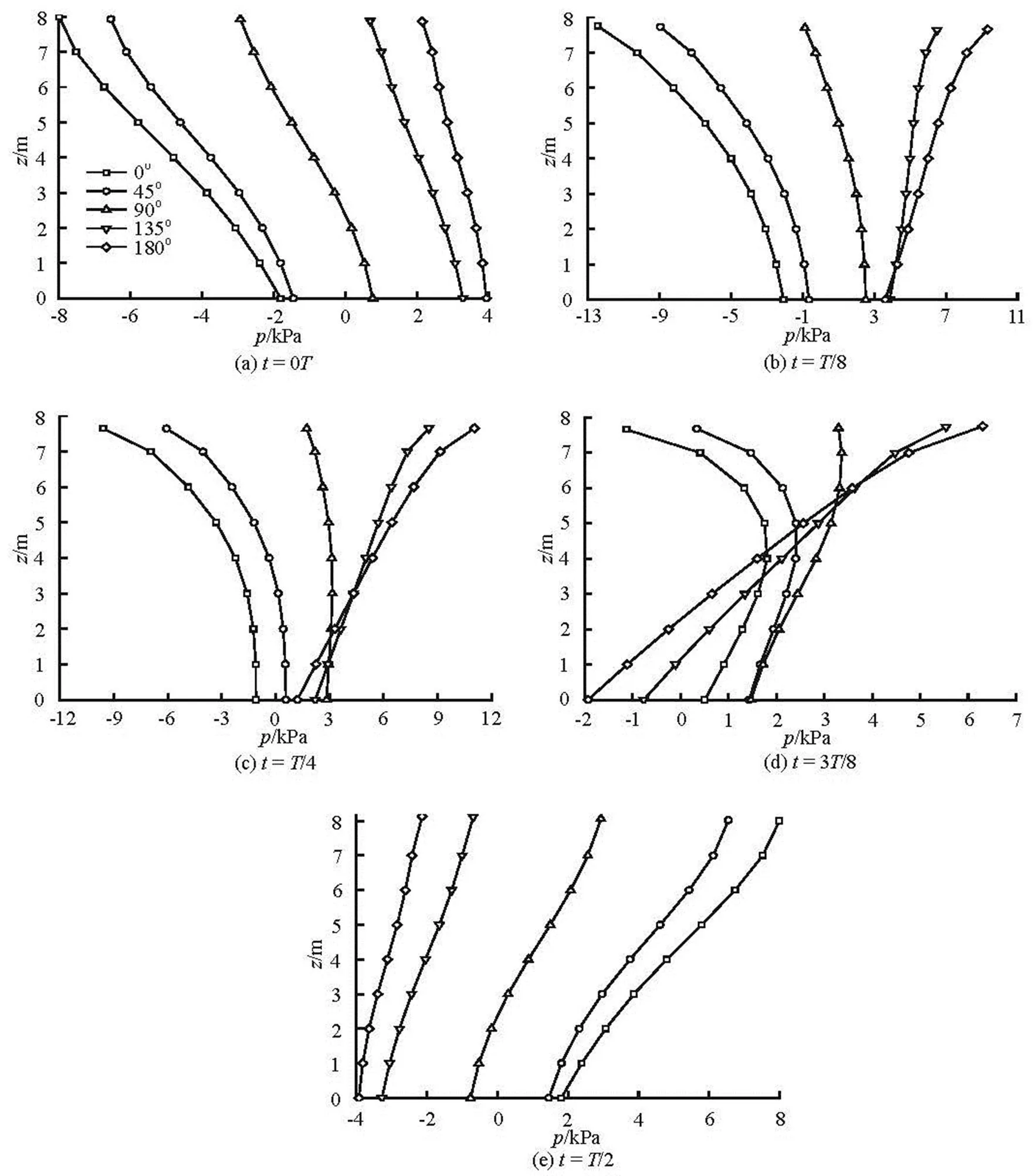
Fig.9 Distributions of wave pressure on the surface of foundation
3.3
The influences of the wave parameters (such as the wave height, the wave period and the water depth) on the wave force on the composite bucket foundation are studied (Fig.10) based on the analytical solution. Figure 10(a) shows the effect of the wave height on the wave force. The maximum wave force increases linearly with the increase of the wave height. It can also be shown that the wave force increases with the increase of the water depth when the wave height and the wave period are constant (Fig.10(b)). The case is complicated in the variation of the wave force with the wave period. For a fixed water depth and wave ampli- tude of the incident wave, the wave force on the com- posite bucket foundation is the highest during a cer- tain wave period (7.5 s) , as shown in Fig.10(c). And it decreases when the wave period increases above 7.5 s. This is because the variation of the wave period affe- cts the value of the wave number in Eq.(22), and the wave force takes a maximum at the wave period of 7.5 s when the water depth is 8.0 m and the wave hei- ght is 0.5 m.
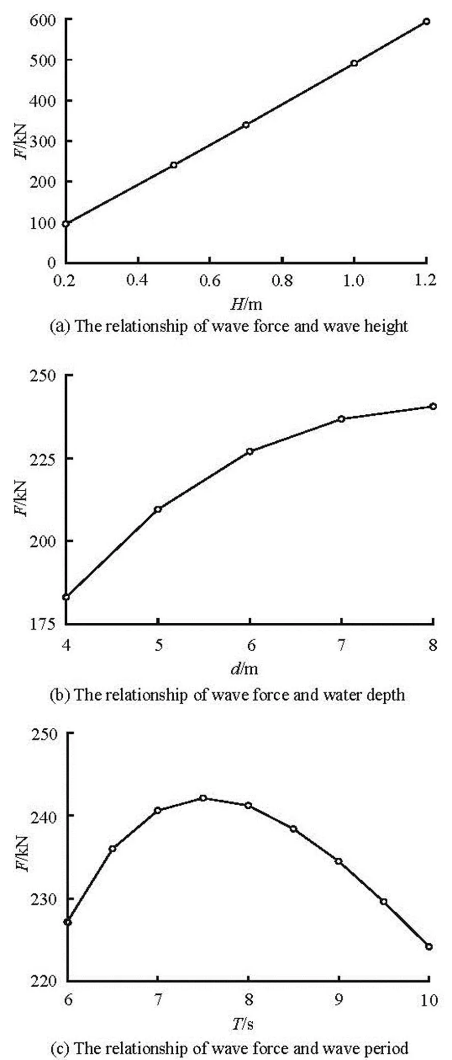
Fig.10 Variation of wave forces under different wave conditions
4. Conclusions
An analytical expression based on the diffraction theory is deduced to calculate the wave force on com- posite bucket foundations, and an experiment for its verification is designed and conducted in the wave flume. After the validation of the analytical results, the variations of the wave pressure on the foundation and the wave force on the composite bucket founda- tion under different wave conditions are discussed.
The complex boundary condition of the composi- te bucket foundation is considered in the diffraction theory to calculate the wave force on the composite bucket foundations. Compared with the previous pie- cewise integration method, the analytical method gives results more consistent with the experimental re- sults and with a high calculation precision.
There is an obvious phase delay of the wave pre- ssure distributions on the front and rear sides of the large-scale composite bucket foundation. The wave force on the composite bucket foundation increases with the increase of the wave height and the water depth. It increases with the increase of the wave pe- riod when the wave period is relatively small, and de- creases with the increase of the wave period after rea- ching the maximum.
The analytical method for calculation of the wave force on the structure is applicable for other size com- posite bucket foundations with any boundary. Additionally, it provides a reference for the study of wave force on other large-scale structures with complex boundary conditions.
Acknowledgement
This work was supported by the Fundamental Research Funds for the Central Universities (Grant No. 201513002).
References
[1] BYRNE B. W., HOULSBY G. T. Foundations for off- shore wind turbines[J]. Philosophical Transactions of the Royal Society of London. Series A: Mathematical, Physical and Engineering Sciences, 2003, 361(1813): 2909-2930.
[2] LIAN Ji-jian, SUN Li-qiang and ZHANG Jin-feng et al. Bearing capacity and technical advantages of composite bucket foundation of offshore wind turbines[J]. Transa- ctions of Tianjin University, 2011, 17(2): 132-137.
[3] LIAN Ji-jian, DING Hong-yan and ZHANG Pu-yang et al. Design of large scale prestressing bucket foundation for offshore wind turbine[J]. Transactions of Tianjin Uni- versity, 2012, 18(2): 79-84.
[4] DING Hong-yan, LIAN Ji-jian and LI Ai-dong et al. One- step-installation of offshore wind turbine on large-scale bucket-top-bearing bucket foundation[J]. Transactions of Tianjin University, 2013, 19(3): 188-194.
[5] KIM N. H., PARK M. S. and YANG S. B. Wave force analysis of the vertical circular cylinder by boundary ele- ment method[J]. KSCE Journal of Civil Engineering, 2007, 11(1): 31-35.
[6] MA H., TANG G. and ZHAO Y. Feedforward and feed- back optimal control for offshore structures subjected to irregular wave forces[J]. Ocean Engineering, 2006, 33(8): 1105-1117.
[7] OHL C. O. G. Water wave diffraction by a cylinder array. Part 1. Regular waves[J]. Journal of Fluid Mechanics, 2001, 442: 1-32.
[8] BAI W., TAYLOR R. E. Numerical simulation of fully nonlinear regular and focused wave diffraction around a vertical cylinder using domain decomposition[J]. App- lied Ocean Research, 2007, 29(1): 55-71.
[9] SONG H., TAO L. Short-crested wave interaction with a concentric porous cylindrical structure[J]. Applied Ocean Research, 2007, 29(4): 199-209.
[10] YOU Yun-xiang, SHI Qiang and MIAO Guo-ping. The ra- diation and diffraction of water waves by a bottom-mou- nted circular cylinder in a two-layer fluid[J]. Journal of Hydrodynamics, Ser. B, 2007, 19(1): 1-8.
[11] CORNETT Andrew, HECIMOVICH Mark and NISTOR Ioan. Extreme wave loads on submerged water intakes in shallow water[J]. Journal of Hydrodynamics, 2015, 27(1): 38-51.
[12] TAO L., SONG H. and CHAKRABARTI S. Scaled boun- dary FEM model for interaction of short-crested waves with a concentric porous cylindrical structure[J]. Journal of Waterway, Port, Coastal and Ocean Engineering, 2009, 135(5): 200-212.
[13] YU X., ZHANG B. An extended analytic solution for combined refraction and diffraction of long waves over circular shoals[J]. Ocean engineering, 2003, 30(10): 1253-1267.
[14] KOO B. J., KIM M. H. Hydrodynamic interactions and re- lative motions of two floating platforms with mooring lines in side-by-side offloading operation[J]. Applied Ocean Research, 2005, 27(6): 292-310.
[15] WILLIAMS A. N., LI W. Water wave interact-ion with an array of bottom-mounted surface-piercing porous cylinde- rs[J]. Ocean Engineering, 2000, 27(8): 841-866.
[16] SHI Qiang, YOU Yun-xiang and MIAO Guo-ping. Diffra- ction of water waves by a vertically floating cylinder in a two-layer fluid[J]. China Ocean Engineering, 2008, 22(2): 4-16.
[17] BATTISTA B. M., KNAPP C. and MCGEE T. et al. App- lication of the empirical mode decomposition and Hilbert- Huang transform to seismic reflection data[J]. Geophysi- cs, 2007, 72(2): H29-H37.
[18] LIU G., ZHANG Q. and ZHANG J. Wave forces on the composite bucket foundation of offshore wind turbines[J]. Applied Mechanics and Materials, 2013, 405-408: 1420-1426.
* Project supported by the Funds for Creative Research Groups of China (Grant No. 51021004), the National Natural Science Foundation of China (Grant No. 51509230).
Biography: Ji-jian LIAN (1965-), Male, Ph. D., Professor
Corresponding author: Tong-shun YU, E-mail: yutongshun607@163.com
10.1016/S1001-6058(16)60605-4 2016,28(1):33-42
水动力学研究与进展 B辑2016年1期
- 水动力学研究与进展 B辑的其它文章
- Flow, thermal criticality and transition of a reactive third-grade fluid in a pipe with Reynoldsʼ model viscosity*
- Investigation of the effects of platform motion on the aerodynamics of a floating offshore wind turbine*
- Mixing of two different electrolyte solutions in electromagnetic rectangular mixers*
- A new biomimicry marine current turbine: Study of hydrodynamic performan- ce and wake using software OpenFOAM*
- Study of bedload transport in backwater flow*
- Experimental study of water and dissolved pollutant runoffs on impervious surfaces*
