Prediction of Crack Growth Rates of a High Strength Titanium Alloy for Deep Sea Pressure Hull under Three Loading Patterns
,,
(1.Shanghai Engineering Research Center of Hadal Scicence and Technology,College of Marine Sciences,Shanghai Ocean University,Shanghai 201306,China;2.China Ship Scientific Research Center,Wuxi 214082,China; 3.State Key Laboratory of Deep-sea Manned Vehicle,China Ship Scientific Research Center,Wuxi 214082,China)
Prediction of Crack Growth Rates of a High Strength Titanium Alloy for Deep Sea Pressure Hull under Three Loading Patterns
WANG Fang1,WANG Ying-ying2,3,CUI Wei-cheng1
(1.Shanghai Engineering Research Center of Hadal Scicence and Technology,College of Marine Sciences,Shanghai Ocean University,Shanghai 201306,China;2.China Ship Scientific Research Center,Wuxi 214082,China; 3.State Key Laboratory of Deep-sea Manned Vehicle,China Ship Scientific Research Center,Wuxi 214082,China)
Fatigue life assessment of deep sea pressure hull has become more and more important due to the increase in the requirement of the safety.The pressure hull during its service life will experience periods of both fluctuating and steady stresses with creep and fatigue involved.This should be treated reasonably but up to now no proper model was proposed.Large uncertainty of the fatigue life assessment results existed in the traditional fatigue life prediction method which often neglected the creep effect.To obtain a better understanding of the problem,the crack growth rates of a beta-annealed titanium alloy TC4 ELI used for deep sea pressure hull is theoretically analyzed in this paper.The crack growth rate prediction models for the three load patterns are respectively introduced. In order to validate the theoretical assumption,a series of crack growth tests under cyclic triangular loading form with a period of overload and dwell time in the stable crack growth region are conducted,which will provide a basis for developing a proper life estimation method of deep sea manned submersibles.
deep sea pressure hull;fatigue crack growth;creep;dwell time
0 Introduction
The pressure hull is the pivotal component of deep manned submersibles,which provides a safe living space for pilots and scientists,and should be designed to have enough strength and be as light as possible[1-2].Fatigue life assessment of deep sea pressure hull has become more and more important due to the increase in the requirement of the safety.
It is well-known that different loading pattern will affect the fatigue life of metal structures.The pressure hull of deep manned submersibles during their service life will experience cyclic periods of loading,then fatigue problem should be properly considered.The fatigue life prediction method based on crack growth rate theory is currently more promising in industry as inside defects of the material is ineluctable.Currently,fatigue strength assessment of the manned sphere of deep sea submersibles has become more and more important in the maintenance process due to the increase in the requirement of the safety which is an extremely complex physical process governed by a great number of parameters related to,for example, fatigue loading behavior,local geometry and material properties of the structural region surrounding the crack growth path.Fatigue loading is the most important parameter.The researchers have realized that the loading history for fatigue prediction of manned sphere is not a normal cyclic history but a rather complex pattern with dwell time.However,most of the existing researches concerning the failure of spherical hull during service as a problem of lowcycle fatigue under a common cyclic load history due to diving task but neglecting the dwell time effect during service beneath the sea.
In order to obtain a proper fatigue design,the fatigue failure with creep interaction due to dwell time has attracted attention even in room temperature which is more easily neglected in the past.Typically,linear accumulation model is used to consider the common interaction of fatigue and creep,e.g.Munz&Bachmann(1980)[3].In the past four decades,significant efforts and progresses have been made to study dwell fatigue and pure fatigue behavior of metal alloys to find out how the material responds to dwell time.The prior research attributes dwell sensitivity to many deleterious mechanisms.However,there is no consensus on the basic cause of the dwell fatigue sensitivity of titanium alloys.Up to now,the problem remains opened on the scientific as well as on the engineering point of view.And till now,there is no proper life prediction model which has been proposed for the manned spheres with dwell time effect considered.To obtain a better understanding of the problem,Fig.1 illustrates three simplified load patterns.Pattern A is a typical constant-amplitude cyclic loading;pattern B is a constant-amplitude cyclic loading with the same dwell time in each cycle(called cyclic creep loading);pattern C is a constant-amplitude cyclic loading with a period of dwell time in one cycle.The crack growth rate law in Pattern A has received lots of studies,e.g. McEvily et al(1999)[4],Sadananda&Vasudevan(2003)[5],and the research on crack growth rate prediction model is still in progress.At the same time,it has been revealed in literature that a period of dwell time in a certain cycle as Pattern C can result in an observable crack growth retardation in some metal materials,e.g.Zhao et al(2006)[6].The retardation mechanism is similar to retardation effect from overload.But for Pattern B in which dwell time exists in each cycle,the crack growth rate is observed to be much higher than that under Pattern A[7].

Fig.1 A schematic illustration of three load patterns
To establish a reasonable fracture mechanics based fatigue life prediction process for deep sea manned pressure hull,improvement of the crack growth rate prediction equations should be proposed first to explain phenomenon of creep effect.In the past several years,the authors’group has made some efforts in improving the ability of the crack growth rate model for marine structures.The extended McEvily model[4]was established progressively by Wang &Cui(2011)[8],et al.And validation on the improved model has been made by comparing the predicted results with test data for a wide range of materials.
In this paper,the improved crack growth rate model considering overload effect is further extended to crack growth rate calculation under the conditions of load patterns B and C shown in Fig.1.The corresponding formulas are introduced and analyzed by comparing the crack growth rate under the three typical loading patterns,especially for TC4 ELI,a beta-annealed titanium alloy as the widely used material in the existing pressure hulls of submersibles.
1 Theoretical model and analysis
A unified fatigue life prediction method is proposed by the authors’group[8],which can be expressed by the following equations,


Considering this phenomenon that the experimental data are closure free at higher load ratio,it is proposed that the term ΔKeffin the constitution relation can be expressed by the above piece-wise function.And Newman’s function[9]for fopis modified by introducing a constraint factor α′as follows,


where A is a material and environmentally sensitive constant of dimensions(MPa)-2;m is a constant representing the slope of the corresponding fatigue crack growth rate curve;n is the index indicating the unstable fracture;KICis the plane strain fracture toughness of the material;KCfis the fracture toughness of the material under fatigue loading which is equal to KICfor simplification;reis an empirical material constant of the inherent flaw length of the order of 1 μm;a is the modified crack length which is equal to re plus the actual crack length;σmaxis the maximum applied stress,σminis the minimum applied stress;Y(a)is a geometrical factor;is a geometrical factor when a is equal to re;R is the stress ratiois the threshold value of stress intensity factor range;athis the threshold value corresponding to ΔKth;ΔKeffis the effective range of the stress intensity factor;ΔKeffthis the effective range of the stress intensity factor at the threshold level;Kopis the stress intensity factor at the opening level;α′is the crack tip stress/strain constraint ratio,which is 1 for the plane stress state and 1/(1-2ν)for the plane strain state.The effect of n is significant only in the unstable propagation region;a constant value of 6 is recommended for a quick and simple engineering analysis. Eq.(4)can be used to determine the value of ΔKeffthand we recommend the values of β and β1are 0.4 and 0.36 respectively for titanium alloys.
Suppose that a short period of dwell time will not induce crack propagation but just result in a monotonic plastic zone.Based on the assumption,Fig.2 is proposed to illustrate the plastic zone distribution for three load patterns together with the change of stress intensity factor in the level of crack opening which will be introduced specifically as follows.
As the basis of crack growth rate model for pattern B and pattern C,the crack growth rate model to consider overload effect will be introduced first.In considering the overload effect,it is assumed that the single overload effect is due to variations in crack closure stress in metals and the large plastic zone as a result of overloading can raise the stress intensity factor at theopening level.A large plastic zone is created as a result of an overload,and the crack closure level instantaneously rises to the maximum value,and then gradually recovers to the initial level under constant loading when the crack penetrates the large plastic zone in the subsequent cycles.A modified coefficient Φ has been introduced as a magnification factor to correct the amount of the stress intensity factor at crack opening level during the recovering period after an overload in the improved constitutive model illustrated in Fig.3.
The coefficient Φ to account for the change of the crack closure level in the improved constitutive model can be defined as follows,
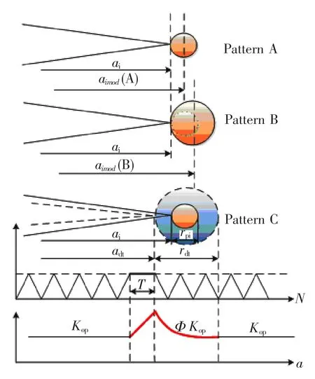
Fig.2 The plastic zone distribution for three load patterns
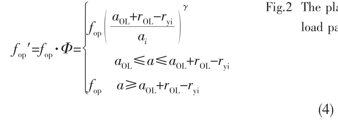
Then it is important to estimate the plastic zone size in front of the crack tip.Liu et al(2006)[10]proposed an equation to calculate the plastic zone size in front of the crack tip as follows,


Fig.3 Schematic representation of the assumed change of Kopunder load sequence with single overloading
The plastic zone size mentioned above is also called monotonic plastic zone,which can be used to calculate the plastic zone due to one overload.As the minimum cyclic load in a cycle is approached,yielding in compression occurs in a region of a smaller size,called the cyclic plastic zone,as expressed in Eq.(6)[11]:

The monotonic plastic zone can be simply modified to the following equation,

where KOLCis the value of stress intensity factor resulting from an instant overload.
Based on the assumption of plastic zone change,Fig.4 is proposed to illustrate the plastic zone distribution due to the cyclic loading with overload and dwell time.Among them, rdtis defined as the plastic zone increment due to dwell time.Then the total monotonic plastic zone can be expressed as the summation of rOLand rdt.And Eq.(4)will be modified to,

Fig.4 Schematic representation of the plastic zone due to cyclic loading with overload and dwell time

The physical mechanisms causing creep in room temperature differ markedly for different classes of materials.In addition,even for a given material,different mechanisms act at various combinations of stress and temperature[12].During low temperature creep(<0.25Tm)of many metals and alloys,primary creep is the dominant deformation mode.At low creep stresses and creep strains(<2×10⁻³),the primary creep deformation of many metals and alloys has been described by a logarithmic creep law of the form ε=llnt+C.In cases where there is larger accumulation of primary creep strains,the deformation can be often described by a power law function of creep strain with time,

where C and k are constants.And the dimension of time T is hour in the present paper.It is supposed that the plastic zone increasing rate with dwell time is the same as the stable creep strain rate under yield stress during the dwell time.Then the value of rdtcan be easily estimated by Eq.(9).
Furthermore,it is supposed that there is an equivalent instant overload stress σOL′as shown in Fig.5 which results in the same plastic zone rOL′as that resulted from the combination effects of the actual instant overload and dwell time,rOL+rdt.

Fig.5 Schematic representation of the load patterns for(a)cyclic loading with overload and dwell time and(b)the cyclic loading with an equivalent overload
Then the equivalent stress intensity factor KOL′can be calculated from the following equation,

Therefore,the crack growth rate for the load pattern of Fig.5(a)can be calculated by combining Eqs.(2),(8)and(10).Pattern C in Fig.1 is a special case of Fig.5(a)when its overload ratio is 1.0.
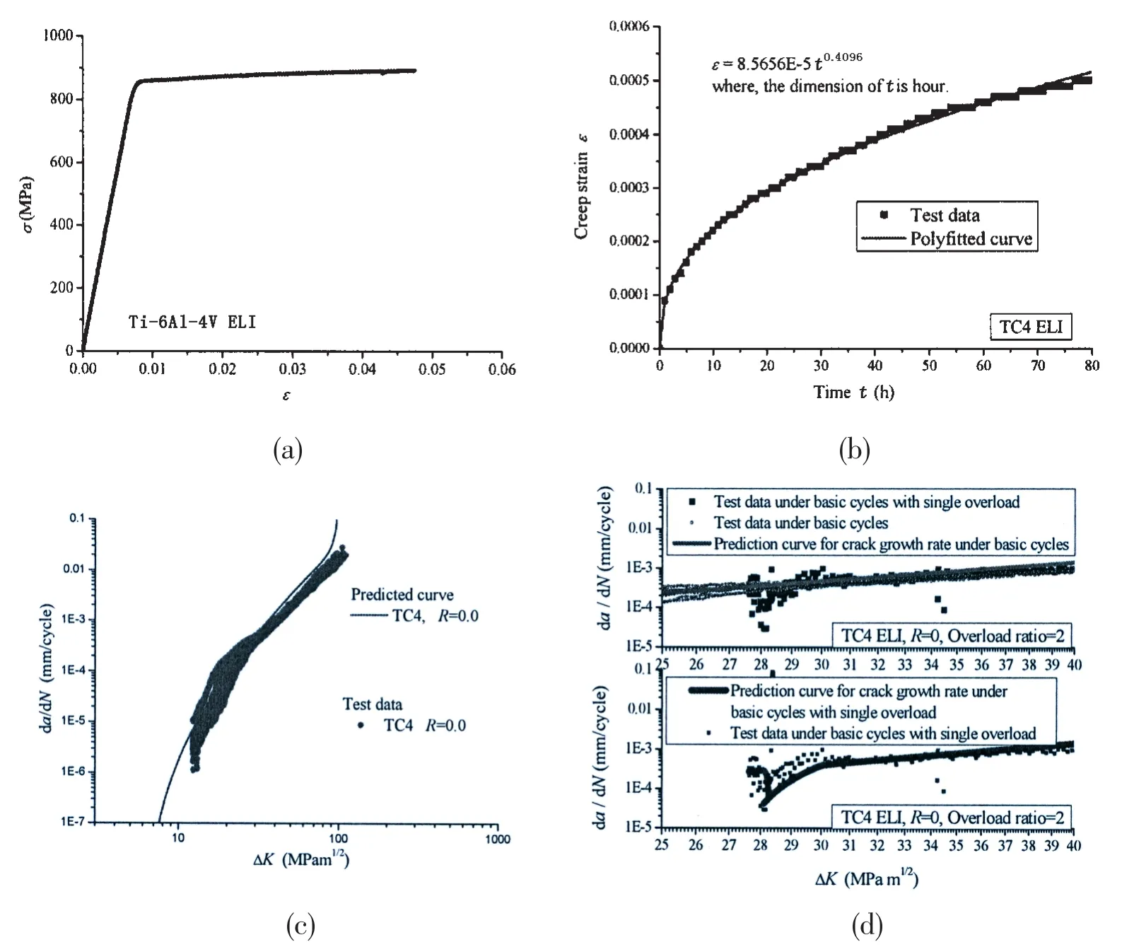
Fig.6(a)Stress-strain curve of the material TC4 ELI used for test;(b)Results of creep strain versus time curve for normal creep of TC4 ELI;(c)Crack growth rate of TC4 ELI under R=0;(d) Comparison between test data of crack growth rate versus cycles under basic loading with and without single overload(TC4 ELI,R=0,Overload ratio=2)
In order to validate the model expressed by Eqs.(2),(8)and(10),a series of basic tests are conducted to obtain model parameters,including a standard tensile test,a standard normal creep test in room temperature on TC4 ELI and a normal crack growth test and a crack growth rate test under basic loading with a single overload are conducted.The results are shown in Figs.6(a)-(d).The crack growth test specimens were conducted using an MTS810 servo-hydraulic testing machine.Standard C-T specimens with dimensions of B=12.5 mm;W=100 mm were cut and machined from 90 mm-thick hot rolled thick plate at load ratio of 0.0 to obtain crack growth rate data.The relationship of strain versus time can be expressed by a power law model as Eq.(9).Another crack growth rate test is conducted on the same C-T specimen undercyclic loading with a period of dwell time at a=14.15 mm.Fig.7 shows the comparison between test data and prediction curve of crack growth rate versus cycles under basic loading with a cycle of 8h dwell time.It can be seen that the prediction model can reasonably reflect the effect of dwell time(Pattern C).
In Pattern B,each cycle has a period of dwell time.It is assumed that the existence of the dwell time will result in a larger plastic zone than that in Pattern A.That means that the elastic-plastic behavior when deriving the nonlinear expression of Kmaxin Eq.(1)should be modified according to the description in McEvily(2001)[13],which introduced that the linear-elastic approach should be extended to include elastic-plastic behavior,i.e.,those cases where the crack-tip plastic zone size is large with respect to the crack length,by increasing the actual crack length,a,by one-half of the plastic zone size.And the Dugdale equation[14]for plastic zone size is adopted for modification. According to this theory,the parameter aimod()B can be written to,
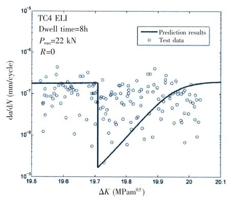
Fig.7 Comparison between test data and prediction curve of crack growth rate versus cycles under basic loading with a cycle of 8h dwell time(TC4 ELI,R=0)

Then the expression of Kmaxfor pattern B can be expressed as follows,

where a is calculated by Eq.(11)for pattern B.Therefore,as Kmaxcontains the dwell time effect,then the modified crack length including half of plastic zone for Pattern B will be larger than that for pattern A,which causes faster crack growth in Pattern B.Fig.8 is an example of crack growth rate curve predicted by the models introduced above.It can be obviously seen from the comparison that there will be clear retardation effect on crack growth due to a period of dwell time in a certain loading cycle and evident acceleration effect on crack growth under cyclic creep condition during the whole crack growth region.The effects on crack growth under Patterns B and C are opposite.For deep sea manned submersibles under normal circumstances,there will be a period of operation time beneath the sea in each diving cycle,then the loading condition is generally close to Pattern B in common sense.Therefore,the acceleration effect due to dwell time existence in each cycle(cyclic creep condition)must be considered when service life estimation of the pressure hull is conducted while the traditional low-cycle fatigue life prediction approach based on damage accumulation theory is too risky.

Fig.8 Comparison between the prediction results of crack growth rate curves for Patterns A,B and C
2 Summary and conclusions
With the improvement of safety requirement of the deep sea manned submersibles,the fatigue life estimation of pressure hull attracts more attention.In order to obtain a better understanding of the loading condition effect on the fatigue life of the deep sea pressure hull,the crack growth rates of a beta-annealed titanium alloy TC4 ELI used for deep sea pressure hull is theoretically analyzed in this paper.The following conclusions can be drawn:
(1)Suppose that a short period of dwell time will not induce crack propagation but just result in a monotonic plastic zone,a model for calculating the effect of overload followed by a period of dwell time in a certain load cycle is proposed based on the crack growth rate model considering one single overload.Accordingly,the separate dwell time effect is regarded as a special case of above condition and the corresponding retardation effect can be taken into account.
(2)When dwell time exists in each load cycle,the change of the plastic zone due to dwell time above the normal cyclic plastic zone should be considered,which directly extends the modified crack length during the calculation of nonlinear stress intensity factor and then causes the acceleration effect on crack growth.The effect is just opposite to that under the load condition with a single dwell time period,but not in contradiction with each other in theory. The acceleration effect due to dwell time existence in each cycle must be considered when service life estimation of the pressure hull is conducted while the traditional low-cycle fatigue life prediction approach based on damage accumulation theory is too risky.
(3)The crack growth rate prediction model under the three load patterns is compared.In order to validate the theoretical assumption,a series of crack growth tests under cyclic triangular loading form with a period of overload and dwell time in the stable crack growth regionhave been conducted.These test results have validated the new crack growth rate prediction model,which will provide a basis for developing a proper life estimation method of deep sea manned submersibles.
Acknowledgments
This work is supported by the State Key Program of National Natural Science of China‘Structural Reliability Analysis on the Spherical Hull of Deepsea Manned Submersibles’(Grant No.51439004),the Scientific Innovation Program Project of‘Key Technology Research and Experimental Validation of Deep Manned Submersible’by the Shanghai Committee of Science and Technology(Grant No.14DZ1205500),Project of Shanghai Engineering Research Center of Hadal Science and Technology(Grant No.14DZ2250900),and the National Hi-tech Research and Development Plan(863 Plan)Project of China(Grant No.2014AA09A110).
[1]ABS.Rules for building and classing underwater vehicles,systems and hyperbaric facilities[S].2010.
[2]Pan B B,Cui W C.An overview of buckling and ultimate strength of pressure hull under external pressure[J].Marine Structures,2010,23(3):227-240.
[3]Munz D,Bachmann V.Effect of hold time and environment on fatigue crack growth rate in Ti alloys[J].Materialwissenschaft und Werkstofftechnik,1980,11(5):168-172.
[4]McEvily A J,Bao H,Ishihara S.A modified constitutive relation for fatigue crack growth[C]//Proceedings of the seventh International Fatigue Congress(Fatigue’99).ed.Wu X R and Wang Z G,Beijing,China,Higher Education Press,1999: 329-336.
[5]Sadananda K,Vasudevan A K.Fatigue crack growth mechanisms in steels[J].International Journal of Fatigue,2003,25 (9):899-914.
[6]Zhao J,Mo T,Nie D F,Ren M F,Guo X L,Chen W X.Acceleration and retardation of fatigue crack growth rate due to room temperature creep at crack tip in a 304 stainless steel[J].Journal of Materials Science,2006,41(19):6431-6434.
[7]Wakai T,Poussard C,Drubay B.A comparison between Japanese and French A16 defect assessment procedures for creepfatigue crack growth[J].Nuclear Engineering and Design,2003,224(3):245-252.
[8]Cui W C,Wang F,Huang X P.A unified fatigue life prediction method for marine structures[J].Marine Structures,2011, 24(2):153-181.
[9]Newman J.A crack opening stress equation for fatigue crack growth[J].International Journal of Fracture,1984,24(4): R131-R135.
[10]Liu Q,Wang F,Huang X P,Cui W C.Three dimensional FE analysis of the plastic zone size near the crack tip[J].Journal of Ship Mechanics,2006,10(5):90-99.
[11]Voorwald H J C,Torres M A S,Pinto Júnior C C E.Modelling of fatigue crack growth following overloads[J].International Journal of Fatigue,1991,13(5):423-427.
[12]Dowling N E.Mechanical behavior of materials:engineering methods for deformation,fracture,and fatigue[M].Prentice Hall,1993.
[13]McEvily A,Ishihara S.On the dependence of the rate of fatigue crack growth on theparameter[J].International Journal of Fatigue,2001,23:115-120.
[14]Dugdale D S.Yielding of steel sheets containing slits[J].Journal of the Mechanics and Physics of Solids,1960,8:100-104.
高强度钛合金深潜器载人舱在三种不同类型载荷下的裂纹扩展预报
王 芳1,王莹莹2,3,崔维成1
(1.上海海洋大学 海洋科学学院 上海深渊科学工程技术研究中心,上海 201306;2.中国船舶科学研究中心,江苏 无锡 214082;3.中国船舶科学研究中心 深海载人装备国家重点实验室,江苏 无锡 214082)
随着安全性要求的提高,深潜器耐压舱的疲劳寿命评估变得越来越重要。对于耐压舱,在其服役期间经历的载荷历程包括扰动疲劳载荷和相对稳定的蠕变载荷,目前尚未有公认合适的模型来描述这一载荷谱历程。传统疲劳寿命预报方法通常忽略蠕变效应导致疲劳寿命预测较大的不确定性。为了更清楚地理解这一机理,该文对深潜器耐压舱用β-退火钛合金TC4 ELI的裂纹扩展率进行了理论分析,分别引入了三种类型载荷作用下的裂纹扩展率模型。并开展了在包含过载和保载载荷的一系列循环三角载荷下的疲劳裂纹扩展试验,对理论模型进行了验证,为合理评估深海载人潜水器的疲劳寿命提供了基础。
深潜器耐压舱;疲劳裂纹扩展;蠕变;保载时间
U661.4
A
王 芳(1979-),女,上海海洋大学副研究员;
U661.4
A
10.3969/j.issn.1007-7294.2016.06.006
1007-7294(2016)06-0699-11
王莹莹(1983-),女,中国船舶科学研究中心博士研究生;
崔维成(1963-),男,上海海洋大学教授,博士生导师。
Received date:2016-04-22
Founded item:Supported by the State Key Program of National Natural Science of China‘Structural Reliability Analysis on the Spherical Hull of Deepsea Manned Submersibles’(Grant No.51439004);The Scientific Innovation Program Project of‘Key Technology Research and Experimental Validation of Deep Manned Submersible’by the Shanghai Committee of Science and Technology(Grant No. 14DZ1205500);Project of Shanghai Engineering Research Center of Hadal Science and Technology (Grant No.14DZ2250900);The National Hi-tech Research and Development Plan(863 Plan)Project of China(Grant No.2014AA09A110)
Biography:WANG Fang(1979-),female,associate professor;WANG Ying-ying(1983-),female,Ph.D.student, E-mail:yunbeidou@yeah.net;CUI Wei-cheng(1963-),male,professor/tutor.
- 船舶力学的其它文章
- Numerical Simulation of Hydrodynamics of Torsional Wave Propulsion in Stationary Water
- High-Frequency Components in Numerical Wave Trains
- URANS Simulation on Diffraction Problem of a Vessel with Transom Stern
- Numerical Simulation of High Velocity Water Impact on the Rigid Plate by Discontinuous Galerkin Method
- Experimental Evaluation on a Newly Developed Dynamic Positioning Time Domain Simulation Program
- Fatigue Reliability Analyses Considering Short Crack and Dwell Time Effects

