URANS Simulation on Diffraction Problem of a Vessel with Transom Stern
(Department of Naval Architecture Engineering,Naval University of Engineering,Wuhan 430033,China)
URANS Simulation on Diffraction Problem of a Vessel with Transom Stern
SUN Xiao-shuai,DONG Wen-cai,YAO Chao-bang
(Department of Naval Architecture Engineering,Naval University of Engineering,Wuhan 430033,China)
Based on an unsteady RANS approach and Volume of Fluid(VOF)method,a numerical wave tank was established by utilizing the User Defined Function(UDF)on FLUENT.Wave generating,propagating and damping were simulated and verified.Wave forces of a complex hull model with bulbous bow and transom stern were computed in head waves.It is found that the wave steepness has a significant effect on the accuracy of numerical wave.Comparison of the results acquired from the present method,experiment and potential theory illustrates that the wave forces are in agreement, while the RANS method provides slightly better prediction in the long waves.
diffraction problem;numerical wave tank;transom;RANS
0 Introduction
The solution of diffraction problem of vessel with speed is the basis of prediction of ship motions in seaway.And a lot of efforts have been made to calculate the wave excitation force. The numerical methods include potential theory and viscous theory.The potential theory has been developed from 2D to 3D,from zero speed to certain speed,from frequency domain to time domain,from linear to nonlinear,with series of progress[1-5].However,the potential theory cannot take the effect of viscosity into consideration,which results in poor ability to predict strong nonlinear motions.To deal with this situation,Chen and Lu[6],Dutykh[7]added viscous effect into potential theory,but it had not been validated.
Due to the rapid development of high-performance computers,the method to calculate ship motions in waves based on RANS has been increasingly popular in contemporary period. Carrica[8-9]developed a software called CFDSHIP IOWA based on RANS to predict ship motions with viscosity such as monohull and trimaran.Guo[10]and Kim[11]utilized two different solvers respectively based on RANS to predict the motions and added resistance of KVLCC2, which indicates good agreement with the experimental results.Wu[12]and Fang[13]built a numerical wave tank based on RANS and computed the wave forces on forwarding Wigley hull in head waves.However,the hull geometries in their studies are relatively simple.
In the present work,based on an unsteady RANS approach and Volume of Fluid(VOF) method,a numerical wave tank is established by utilizing the User Defined Function(UDF). Wave making and propagation were simulated and verified.Wave forces of a complex hull model with bulbous bow and transom stern were computed in regular head waves.Comparison of the results acquired from the present method,experiment and potential theory illustrates that the wave forces are in agreement.The present method based on RANS can precisely simulate the flow field around the hull and provides slightly better prediction in the long waves.
1 Numerical model
1.1 Viscous flow control equations and turbulent mode
Viscous flow control equations contain continuity equations and momentum equations, which are shown as:

where ρ is the fluid density,μ is the fluid viscosity degree,p is the static pressure,fiis the mass force,ui,ujis the velocity component.
Turbulent model is RNG k-ε,which shows as follows:
Turbulent fluctuation kinetic energy equation(k equation)is:

Turbulent energy dissipation rate equation(ε equation)is:


The free surface is captured by the Volume of Fluid(VOF)method,which is shown as:

where q=1,2,a1and a2refer to the volume of air-phase and water-phase.
1.2 Numerical wave tank
The numerical wave tank that can precisely generate the required wave is significant to solve the diffraction problem.It consists of wave-generating zone,working zone and damping zone,which is depicted in Fig.1.

Fig.1 Numerical wave tank
The boundary simulation by inputting the velocity function of wave at the inlet is utilized to generate wave.In the theory of infinite linear wave,the wave surface and velocity function of regular wave in the fixed coordinate system shows as follows:

where A is the amplitude,k0is the wave number,ω0is the wave frequency,O0x0is the wave propagate direction,O0y0is the transverse direction,O0z0is the fluctuant direction.
In the reference coordinate system,Oxyz that move with the hull at the velocity U0,the wave surface and velocity function of regular wave are shown as:

where ωeis the encounter frequency,β is the wave to course angle.ωe=ω0-kUcos β.
A damping zone extends 1.5 times of wave length is set before the output boundary.In order to maintain the continuity of horizontal flow,the damping is just applied to the vertical velocity.The damping coefficient is

where γ is the control parameter of damping coefficient,xsand xeare the x coordinate of the start point and end point of the damping zone,zband zfare the z coordinate of the damping zone bottom and free surface.
1.3 Numerical hull and boundary condition
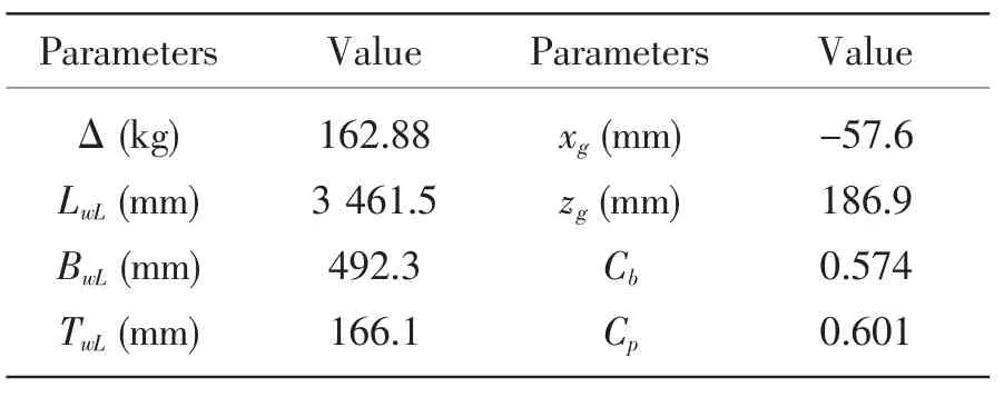
The numerical model is a hull with bulbous bow and transom stern.The main parameters of the hull are shown in Tab.1.
The calculation field mesh and boundary conditions are shown in Fig.2.The total length of the calculation field changes with the wave length λ.The inlet is 1λ ahead of the bow and is set as velocity-inlet which is defined by UDF.It is divided into upper and lower layers along the waterline.While the upper layer is air,the lower layer is water.The outlet is 3λ behind the stern and is set as pressure-out,where the pressure value increases with the water depth.The bottom face is one hull length away from the hull and is set as symmetry.The side face is also one hull length away from the hull and is set as velocity-inlet.The length of the damping zone is 1.5λ.The hull surface is set as wall,which meets the impenetrable condition and no-clip condition.The direction of gravity is perpendicular to the static water.
Tab.1 Main parameters of the numerical model
The calculation field is dispersed by full structured grid in ICEM.The total number of the fluid domain meshes is about 1.5 million.The meshes near the waterline and in the normal direction of hull surface are refined to acquire precise information about the free surface and flow filed around the hull.The thickness of first layer grid around the hull varies from 1 mm to 2 mm and the value of y+is 40 to 200.The grid of the damping zone increases along the wave spreading direction to provide numerical damping.

Fig.2 Calculation field mesh and boundary conditions
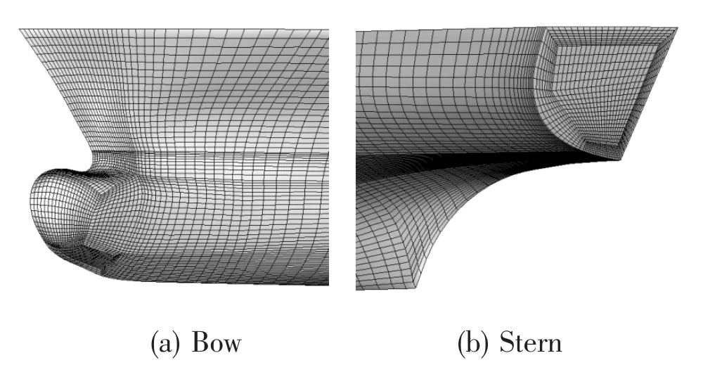
Fig.3 Meshes of the hull
The discrete control equations are second order upwind.The method utilized to couple velocity and pressure is SIMPLEC.The calculation solver is unsteady,with the average time step being Te/400,where Teis the wave encounter period.
2 Simulation of the numerical wave
Aiming at precisely building the numerical wave tank and verifying the generation,propagation and absorption of wave,some factors such as grid discretization,turbulence model,time step size and wave steepness were discussed in the two dimensional wave tank.It is found that the wave steepness is a significant factor that affects the accuracy of the numerical wave.
In detail,the wave length is fixed at 6 m and the wave height varies from 0.02 m to 0.8 m,thus the wave steepness changes from 1/300 to 2/15.The mesh size in the longitudinal is Δx= 1/20λ,while that in the vertical direction is Δy=1/10hw.The steady numerical wave surfaces are shown in Fig.4.

Fig.4 The wave pattern of different hw/λ
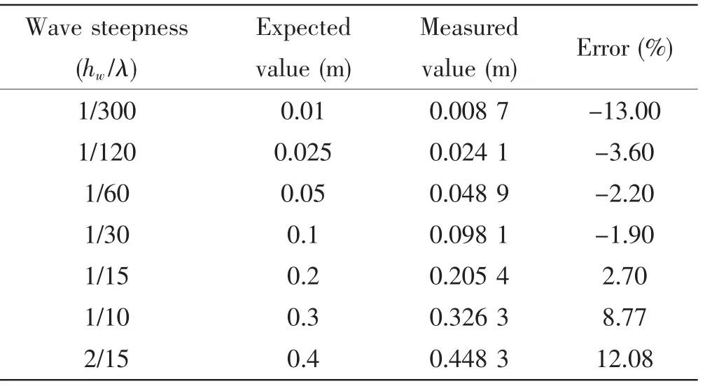
The comparison of the wave amplitude at x=6 m of various wave steepness is shown in Tab.2.It can be seen that the wave height shrinks significantly by about 13%after the first wave length when the wave steepness is 1/300,while the wave height trends to be larger than the expected value by 8.77%when the wave steepness is more than 1/10.By contrast, the error of wave height is within 3.70% when the wave steepness varies from 1/120 to 1/15,which is relatively acceptable in the numerical simulation.Thus,it is recommended that the wave steepness should be kept between 1/120 and 1/15.
Tab.2 The comparison of the wave amplitude at x=6 m

Fig.5 The wave pattern of different turbulent model

Fig.6 The wave pattern of different time step
By comparing the results of various mesh cases,it is found that the result is good enough when Δx is smaller than 1/20λ and Δy is smaller than 1/10hw.Besides,the turbulent models such as the inviscid,k-ε RNG,standard k-ε and k-ω SST have little influence on the results.Additionally,the wave height is accurate when the time step size equals 1/400Teand continuing to decrease the time step size gains no benefit,but a significant increase in the total calculation time.
The three dimensional numerical wave tank is built based on the two dimensional one. The Fig.7 depicts the wave surface of the regular wave coming from different directions(λ=6 m, hw=0.1 m).

Fig.7 Simulation of regular wave(λ=6 m,hw=0.1m)
A wave height probe is set six meters after the inlet boundary.The comparison of history of wave elevation between the numerical wave and the theory wave is shown in Fig.8.As depicted in Fig.8,the results depict good agreement,which verifies the wave generating method. Besides,the numerical wave trough is smoother than the theory one,which indicates viscous and non-linear effect.
The steady wave pattern of the NWT free surface is shown in Fig.9.While no attenuation of the wave height is found along the wave propagating direction before the damping zone,the wave surface becomes smooth in the damping zone.

Fig.8 History of wave elevation at point x=6 m from inlet

Fig.9 The wave pattern of tank free surface
3 Results and analysis of the diffraction problem
The model is zero trim and fixed during all the test cases.The calculated Fnis 0.153 and 0.175.The wave height is 0.12 meter.The wave length changes from two meters to twelvemeters and λ/L changes from 0.578 to 2.889.
3.1 Wave pattern
The flow field with free surface around the hull is depicted in Fig.10(Fn=0.175).The waves motivated by the advancing hull,the incident wave,the radiation wave and the diffraction wave interfere with each other,while in the damping zone the wave surface becomes smooth.
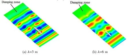
Fig.10 The field with free surface around the hull(Fn=0.175)
3.2 Wave forces
The history of the wave forces of the advancing hull in head regular wave is depicted in Fig.11(λ=6 m,Fn=0.175).

Fig.11 Wave force of model in head regular wave(λ=6 m,Fn=0.175)
The Fourier Series(FS)were utilized to analyze the unsteady histories of the wave forces. Since the first order amplitude is the main factor that we pay attention to,the history of the wave forces can be described as follows:

where ωeis the encounter frequency,F1a,F2aand F3aare the first order surge force,heave force,and pitch moment.F10,F20and F30are the zero order surge force,heave force,and pitch moment.ε1,ε2and ε3are the phases of the surge force,heave force and pitch moment.
The numerical results are converted into non-dimensional form in order to compare with the experimental results.The non-dimensional functions are shown as follows:

The non-dimensional wave forces of the hull model in head regular waves at different Fnfrom the present method,experiment and potential theory are shown in Figs.12~14.The results of potential theory are based on the three-dimensional translating and pulsating source Green’s function(3DTP)[5].

Fig.12 Surge forces in head regular waves at different Fn
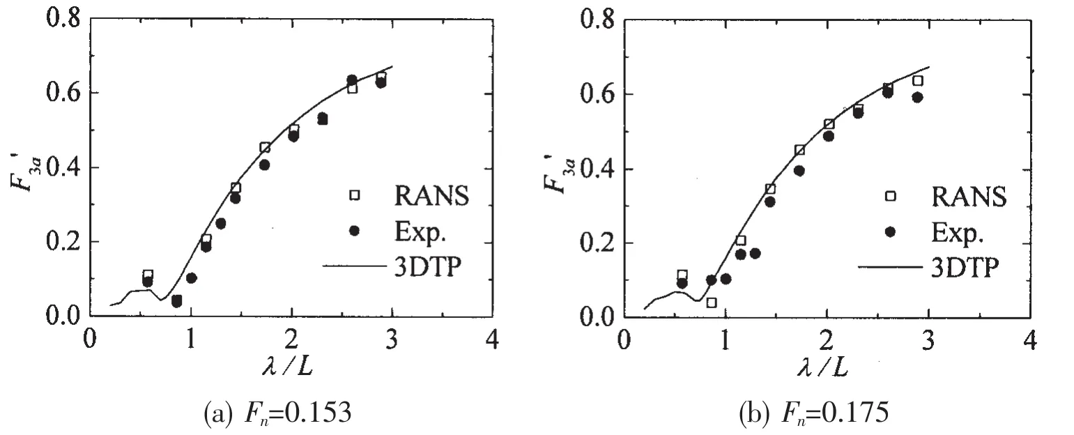
Fig.13 Heave forces in head regular waves at different Fn
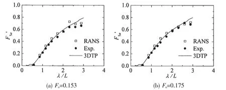
Fig.14 Pitch moments in head regular waves at different Fn
Overall,the wave forces based on RANS,experiment and potential theory are in good agreement.The surge forces based on RANS are slightly bigger than the results based on experiment and potential theory,while there are just minimal differences between the results based on RANS and the experiment in terms of the heave forces and pitch moments.Besides,it can be seen that the RANS methods give better prediction in the long waves.It can be concluded that the numerical method based on RANS takes the viscous and nonlinear effect into consideration and results in a more accurate simulation of the flow field.
4 Conclusions
Based on an unsteady RANS approach,utilizing the Volume of Fluid(VOF)method to capture the free surface,a numerical wave tank is established by using the User Defined Function(UDF)on the commercial code Fluent.Wave forces of a complex hull model with bulbous bow and transom stern were calculated in head waves.Comparison of the results acquired from the present method,experiment and potential theory are made.The main conclusions are as follows.
(1)The wave steepness has a significant effect on the wave accuracy in the numerical wave tank.
(2)Compared with the experimental data,both RANS method and 3DTP method give good prediction of the wave forces,while the RANS method gives slightly better result in the long wave range.
[1]King B K,Beck R F,Mageee A R.Seakeeping calculations with forward speed using time domain analysis[C].Proc.17th Symp.On Naval Hydrodynamics,1988:577-596.
[2]Song M J,Kim K H,Kim Y.Numerical analysis and validation of weakly nonlinear ship motions and structural loads on a modern containership[J].Ocean Engineering,2011,38(1):77-87.
[3]Noblesse F and Hendrix D.On the theory of potential flow about a ship advancing in waves[J].Journal of Ship Research, 1992,36(1):17-29.
[4]Noblesse F,Huang Fuxin,Yang Chi.Evaluation of ship waves at the free surface and removal of short waves[J].European Journal of Mechanics B/Fluids,2013,38(3):22-37.
[5]Yao C B,Dong W C.A fast integration method for translating-pulsating source Green’s function in Bessho form[J].Journal of Zhejiang University-A,2014,15(2):108-119.
[6]Chen X B,Lu D Q.Time-harmonic ship waves with the effect of surface tension and fluid viscosity[C]//Proceedings of the 24th International Workshop on Water Waves and Floating Bodies.Zelenogork,Russia,2009.
[7]Dutykh D.Visco-potential free surface flows and long wave modeling[J].European Journal of Mechanics B/Fluids,2009, 28(3):430-443.
[8]Carrica P M,Wilson R V,Stern F.Unsteady RANS simulation of the ship forward speed diffraction problem[J].Computers &Fluids,2006,35(6):545-570.
[9]Carrica P M,Wilson R V,Noack W,et al.Ship motions using single-phase level set with dynamic overset grids[J].Computers&Fluids,2007,36(9):1415-1433.
[10]Guo B J,Steen S,Deng G B.Seakeeping prediction of KVLCC2 in head waves with RANS[J].Applied Ocean Research, 2012(35):56-67.
[11]Kim J,Park I,Kim K,et al.Numerical towing tank application to the prediction of added resistance performance of KVLCC2 in regular waves[C].Proceedings of the 2013 International Offshore and Polar Engineering,2013:880-886.
[12]Wu C S,Zhu D X,Gu M.Computation of hydrodynamic forces for a ship in regular heading waves by a viscous numerical wave tank[J].Journal of Ship Mechanics,2008,12(2):168-179.(in Chinese)
[13]Fang Z Z,Zhu R C,Miao G P,et al.Numerical simulation of diffraction problems of moving vessels in numerical wave tank[J].Journal of Shanghai Jiaotong University,2012,46(8):65-72.(in Chinese)
方尾船绕射问题RANS求解研究
孙小帅,董文才,姚朝帮
(海军工程大学 舰船工程系,武汉 430033)
基于RANS方程,采用VOF方法捕捉自由液面,通过自定义函数UDF在Fluent平台上建立了三维数值波浪水池,模拟了规则波的生成、传播和消波,发现波陡对数值造波的精度有较大影响。求解了规则波中顶浪航行的方尾船模型的波浪力,并与试验结果和势流理论结果进行了比较。结果表明,基于RANS方程的波浪力计算结果与试验结果和势流理论结果吻合良好,在长波中与试验值更接近。
绕射问题;数值波浪水池;方尾;RANS
U661.1
A
国家自然科学基金项目(50879090);水动力重点基金项目(9140A1403071251311044)
孙小帅(1990-),男,海军工程大学舰船工程系博士研究生;
U661.1
A
10.3969/j.issn.1007-7294.2016.06.003
1007-7294(2016)06-0664-10
董文才(1967-),男,海军工程大学教授,博士生导师。
Received date:2015-12-12
Foundation item:Supported by the National Natural Science Foundation of China(No.50879090)and by the Key Program of Hydrodynamics of China(No.914A14030712JB11044)
Biography:SUN Xiao-shuai(1990-),male,Ph.D.student of Naval University of Engineering,E-mail: hglastshadow@163.com;DONG Wen-cai(1967-),male,professor/tutor,haigongdwc@163.com.
- 船舶力学的其它文章
- Numerical Simulation of Hydrodynamics of Torsional Wave Propulsion in Stationary Water
- High-Frequency Components in Numerical Wave Trains
- Numerical Simulation of High Velocity Water Impact on the Rigid Plate by Discontinuous Galerkin Method
- Experimental Evaluation on a Newly Developed Dynamic Positioning Time Domain Simulation Program
- Prediction of Crack Growth Rates of a High Strength Titanium Alloy for Deep Sea Pressure Hull under Three Loading Patterns
- Fatigue Reliability Analyses Considering Short Crack and Dwell Time Effects

