高速扫描摄影中光学偏转加速技术研究
艾月霞,陈红艺,李景镇,吴庆阳,蔡 懿
深圳微纳光子信息技术重点实验室,深圳大学电子科学与技术学院,广东深圳 518060
高速扫描摄影中光学偏转加速技术研究
艾月霞,陈红艺,李景镇,吴庆阳,蔡懿
深圳微纳光子信息技术重点实验室,深圳大学电子科学与技术学院,广东深圳 518060
摘要:分析并设计了一种新型的光学偏转加速装置,可以对入射光束偏转角度进行倍数放大.该装置利用曲面反射原理,当入射光束发生很小的原始偏转时,其反射光束随之发生偏转且其偏转角度被放大.可通过调节曲面反射镜的曲率来实现微小光学偏转角度放大1~2个数量级.该种技术主要用于非管扫描相机,比如转镜相机、电光晶体偏转相机及其他光学扫描器件,无机械装置,更适合小角度的电光偏转以及古斯-汉欣位移等光学偏转加速.
关键词:扫描相机;电光偏转;光学偏转加速;高速摄影;古斯-汉欣位移;扫描器件
In the field of microsecond imaging, the interest is back to high speed rotating mirror cameras. To date, in fact, there has been no electronic camera yet that can match a rotating mirror camera with film, which possesses a bigger frame format of 102mm2order, more frame count than a hundred frames, higher spatial resolution, larger dynamic range of 103or more, and so on. Lai et al[1-2]have done the innovative and valuable researches on it. This kind of camera is predominantly used in the field of shock waves and detonation physics[3-5]. In the Shardin formula, optical information capacity which is the product of imaging frequency ν, spatial resolution N and the size of frame B in the time direction depends on the rotating mirror edge line-speed νpand the wavelength of light λ. Having considered the optical accelerating, the Shardin’s formula is perfected by
BNν=2βνp/λ
(1)
where β, the most important parameter in the optical accelerating circle, is an optical accelerating factor of 2~200 usually.
1Multi-reflection accelerating
The multi-reflection accelerating can multiply the deflection speed of the incident light-beam on the reflective surface of rotational mirror and can be divided into two schemes[6-9]: multi-reflection with wadge-gap-shaped retroreflector and multi-reflection with rotating polyhedron mirror. According to the law of reflection, the factor β for this kind of optical accelerating can be expressed by
β=2n
(2)
where n is the number of reflection on rotational reflecting surfaces of the wadge-gap-shaped retroreflector or the rotating polyhedron mirror. And the angular velocity Ω of the outgoing beam after reflecting can be written as Ω=2nω, where ω is the angular velocity of the retroreflector or the rotating polyhedron mirror.
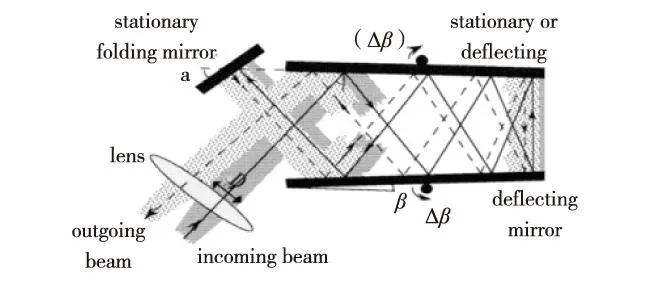
The multi-reflection with wadge-gap-shaped retroreflector has especially promoted the rotating mirror streak camera with temporal resolution of nanosecond. As is shown in Fig.1[10], the deflection mode of galvanometer with the wedge-gap-shaped retroreflector is the combination of a rotational mirror and a stationary mirror, or two rotational mirrors with opposite directions. The streak camera prototype, based on this retroreflector, is an important breakthrough in the rotating mirror imaging field, and has a lot of excellent performances such as higher sensitivity, broader linear dynamic region, finer spatial contrast (a spatial resolution of 10 lp/mm), high temporal resolution (11.4 ns at 3.8 ns/pixel), larger information capacity and better adaptability, compared with the electronic camera, side-by-side testing.

Fig.1 Optical accelerating with wadge-gap-shaped retroreflector图1 楔形缝隙回射器光学加速
The version of the galvanometer mentioned above, the wadge-gap-shaped retroreflector formed by a pair of rotating mirrors of two cones with opposite direction, is one of classical cameras and available in operation[11].
In this scheme, the number of reflection n, directly dominating the angular velocity of the outgoing beam which determines the optical information capacity for the framing imaging or the temporal resolution for streak imaging, is 16 for the double rotational mirrors with opposite direction and additional stationary folding mirror. The number of reflection n which is dependent upon the incident angle ψ of the imaging beam, the inclination δ between two deflecting mirrors, and the reflectivity of the mirrors, can be written by
n=2(ψ/δ+1)-1
(3)
Another multi-reflection with rotating polyhedron mirror has several models of combination of polyhedron mirrors with static mirrors to give birth to different accelerating factors. For example, as shown in Fig.2[11], the accelerator is composed of a rotating nine-sided mirror polyhedron 1, a collimating lens 2 and a triple prism 3, which is a typical arrangement with the optical accelerating factor β of 4 which means that as the polyhedron rotates by an angle of θ, the light beam rotates by an angle of 4θ.

Fig.2 Optical accelerating with combinations of polyhedron mirrors and stationary triple prism图2 多面体镜和三棱镜复合光学加速
Both the multi-reflection with wadge-gap-shaped retroreflector and the multi-reflection with rotating polyhedron mirror, practically applied to the rotating mirror cameras, should meet two conditions. One condition is to be provided with a very exact rotating device, and the other one is to make the relative locations between the multiple reflecting light-beam and the reflective mirrors accurate. Therefore, the multi-reflection accelerating should be performed by accurately calculating and designing, and its device is complicated in structure and high in cost.
2Deflection amplification accelerating
The deflection amplification accelerating, different from that mentioned above and carried out by a curved surface mirror, is a new optical accelerating technique in which the small deflecting angle is to be amplified, continuously.
The key point of the accelerating is to mainly make the incident light-beam with tiny deflecting angles or tiny displacements sequentially be projected on different locations of a spatially curved surface to form different incident angles during the deflecting period. Based upon the law of reflection, the reflective angle and its incident angle are equal and continuously changing. The change range of the reflective angles is limited by the incident light-beam locations on the curved surface and the curvature of the curved surface which can both be designed according to requirements. Therefore, both scanning of the incident light-beam and amplifying deflection angles can be performed. The optical accelerating factor β is related to structural parameters, such as the relative location of the system configured for generating the original tiny deflections and displacements, and the curvatures of the curved surface.
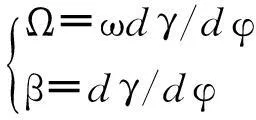
As a rule, in this situation, the optical accelerating equation can be expressed by

(4)
where, as shown in Fig.3, φ is an original tiny deflection angle, γ is formed by the outgoing beam with the incident beam, Ω is the accelerated angular velocity and ω is the original angular velocity generated by an electro-optical deflector. Here, the optical accelerating factor β is around 2 to 200 usually. The optical information capacity of this kind of imaging technique which is now with advantage in the nanosecond and sub-nanosecond imaging field, can be increased by 1 to 2 orders of magnitude.

Fig.3 Schematic diagram of optical deflecting amplification accelerating图3 光学偏转加速示意图
As shown in Fig.3, r is a radius of the cylindrical reflector and its curvature is ρ=1/r. Its normal crossesx-axis at point C. An incident angle at an incident point T is θ, thus its deflection angle relative to an incident optical axis is γ=2θ+φ, and θ=φ+α. Now the optical accelerating factor β can be deduced as follows
(5)
As shown, β is not a constant from Eq.(5) for this reflective mirror. When the original deflection angle φ is tiny,α and θ are small enough, β can be approximately written by
β=dγ/dφ=2ρL+1
(6)
where L is a distance between an original deflection point and a vertex of the cylindrical-surface reflective mirror. As it is seen from Eq.(6) , the optical accelerating factor is determined by ρ and L, and β is a constant in this supposed condition.
Now we can further study the optical accelerating factor β. As it is shown, β is not a constant from Eq.(5) for the cylindrical reflector. In general, if the reflective curved mirror is some transcendental curved cylindrical-surface, described by the following differential Eq.(7) , the optical accelerating factor could be a constant:
(7)
where the initial condition is (L,0). And as tan-1(y/x)~y/x, then Eq.(7) can be deduced to
(8)
The analytic solution of Eq.(8) is
x2-y2(β-1)/2=L2
(9)
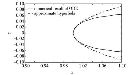
As shown in Fig.4, the blue curve for the analytic solution of Eq.(9) is in very good agreement the black curve for the numeric solution of Eq.(7) near y=0 when β=50.

Fig.4 The analytic solution of Eq.(9) and the numeric solution of Eq.(7) (x-axis normalized by length L)图4 方程(9)的解析解和方程(7)的数值解 (横坐标轴长度L已归一化处理)
According to Eq.(6), the optical accelerating factor β can be increased more if ρ increases. However, when ρ increases, the radius of the curved-surface reflective mirror will be decreased. Thus the curced-surface mirror is difficult to process and apply. Generally speaking, the light-beam deflection angle or the deflection speed can be improved by one to two orders of magnitude. In addition, no mechanical moving device is found in this accelerating device, such as the rotating polyhedron mirror and the retroreflector. Thus it is simple and more suitable for cooperating with the electro-optical deflection and the Goos-Hänchen displacement[12-13]to accelerate the light-beam deflection.
It is found that the deflection amplification accelerating can be used to improve the temporal resolution of the crystal-streak camera[14]20.0 ps to 2.5 ps[15]at least.
Conclusion
Two kinds of accelerating principle, mentioned above, are very useful and available in the ultra high speed rotating mirror cameras, framing and streak, and electro-optical deflecting recording devices. Both the multi-reflection accelerating and the deflecting amplification accelerating can effectively accelerate the deflecting speed of the incident light-beam for greatly increasing the optical information capacity. However, the former is complicated in structure and high in cost. The latter, different from the former, is a newly invented optical deflecting technique, in which the small deflecting angle can be amplified by one to two orders of magnitude. Its device, moreover, may have not any mechanical rotating parts, so it is simple and more suitable for cooperating with the electro-optical deflection and the Goos-Hänchen displacement to accelerate the light-beam deflection.As having simultaneously considered both the multi-reflection accelerating and the deflecting amplification accelerating, the optical accelerating factor β should be expressed by
β=2ndγ/dφ
(10)
On the understanding that n=16,dγ/dφ=16, which are reasonable and reliable, the factor β=512, which suggests an attractive prospect.
At last, the optical deflection accelerating techniques, upgrading the optical information capacity, can be applied to the ultra-high speed rotating polyhedron mirror devices and other scanning devices. Especially, the optical-deflection amplification accelerating, useful and available, may have a great perspective.
引文:艾月霞,陈红艺,李景镇,等. 高速扫描摄影中光学偏转加速技术研究[J]. 深圳大学学报理工版,2016,33(2):134-137.(英文版)
References / 参考文献:
[1] Lai C C, Goosman D R, Wade J T, et al. Design and field test of a galvanometer deflected streak camera[C]// The 25th International Congress on High Speed Photography and Photonics. Proceedings of SPIE. Beaune, Finland: SPIE, 2003, 4948:330-335.
[2] Frank A M, Bartolick J M. Solid state replacement of rotating mirror cameras[C]// The 27th International Congress on High Speed Photography and Photonics. Proceedings of SPIE. Xi’an, China: SPIE, 2007: 62791U-1-62791U-9.
[3] Held M. Simultaneously gained streak and framing records offer a great advantage in the field of detonics[J]. Propellants Explosives Pyrotechnics, 2001, 26(3): 148-155.
[4] Liang Lingliang, Tian Jinshou, Wang Tao, et al. Theotrtical and static experiment research on all optical solid state streak camera[J]. Acta Physica Sinica, 2014,63(6):060702-1-060702-7.(in Chinese)
梁玲亮, 田进寿, 汪韬, 等. 全光固体条纹相机的理论及其静态实验研究[J]. 物理学报, 2014,63(6): 060702-1-060702-7.
[5] Wang Feng, Wei Huiyue, Wei Xin, et al. Design and experimental research of all-optical scanning device[J]. High Power Laser and Particle Beams, 2013, 25(9):2213-2217.(in Chinese)
王峰,魏惠月,韦欣,等. 全光扫描装置设计及实验研究[J]. 强激光与粒子束, 2013, 25(9):2213-2217.
[6] Li Jingzhen. Time amplifying techniques towards atomic time resolution[J]. Science in China, 2009, 52(12): 3425-3446 .
[7] Li Jingzhen. Handbook of optics[M]. Xi’an: Shaanxi Science and Technology Press,2010:2195-2199.(in Chinese)
李景镇. 光学手册[M]. 西安:陕西科学技术出版社,2010:2195-2199.
[8] Liu Chunping,Li Shuang, Li Jingzhen, et al. A shutter pulse generator for high speed camera[J]. Journal of Shenzhen University Science and Engineering, 2013,30(2):133-137.(in Chinese)
刘春平,李爽,李景镇. 一种用于高速摄影仪的快门脉冲发生器[J]. 深圳大学学报理工版,2013,30(2):133-137.
[9] Li Chunbo, Yu Chunhui, Li Jingzhen, et al. Structure design of rotating mirror based on the topology optimization theory for ultra-high speed camera[J]. Journal of Shenzhen University Science and Engineering, 2012, 29(4):304-310.(in Chinese)
李春波,余春晖,李景镇,等. 基于拓扑理论的超高速摄影仪转镜结构设计[J]. 深圳大学学报理工版,2012, 29(4):304-310.
[10] Lai C C, A new tubeless nanosencond streak camera based on optical deflection and direct CCD imaging[C]// The 20th International Congress on High Speed Photography and Photonics. Proceedings of SPIE. Columbia, Canada: SPIE, 1992, 1801:454-469.
[11] Dubovik A S. The photographic recording of high-speed processes[M]. New York, USA: John Wiley, 1981:227-240.
[12] Liu Xuanbin, Cao Zhuangqi, Zhu Pengfei, et al. Simultaneously large and opposite lateral beam shifts for TE and TM modes on a double metal-cladding slab[J]. Chinese Physics Letters, 2006, 23(8): 2077-2079.
[13] Liu Xuanbin, Cao Zhuangqi, Zhu Pengfei, et al. Large positive and negative lateral optical beam shift in prism waveguide coupling system[J]. Physical Review E: Statistical Nonlinear & Soft Matter Physics, 2006, 73(5 Pt 2):88-101.
[14] Ireland C L M. A 20 ps resolution crystal streak camera[J]. Optics Communications, 1979,30(1): 99-103.
[15] Ai Yuexia, Li Jingzhen. Study on a new crystal streak camera with ~ 2.5 ps resolution[C]//The international Symposium on Photonics and Optoelectronics. Shanghai, China:IEEE,2012:580-582.
【中文责编:晨兮;英文责编:木南】
Optical-deflection accelerating techniques in streak camera
Ai Yuexia, Chen Hongyi†, Li Jingzhen, Wu Qingyang, and Cai Yi
Shenzhen Key Laboratory of Micro-Nano Photonic Information Technology, College of Electronic Science and Technology,Shenzhen University, Shenzhen 518060, Guangdong Province, P.R.China
Abstract:To get more precise high-speed streak cameras, we analyze a novel optical-deflection accelerating technique for light-beam. When the incident light-beam is deflected with a tiny initial deflection angle, according to the law of curved surface reflection, the reflective light-beam is deflected therewith and the deflection angle is enlarged. The deflecting amplification accelerating device can amplify the small deflecting angle by one to two orders of magnitude through adjust the curvature of the curved-surface. This device dominates the optical information capacity in tubeless streak camera, such as rotating mirror cameras, electro-optic crystal deflector cameras, and other light-beam scanning devices. Because there is no mechanical moving part in the new-developed device, this technique is suitable for cooperating with electro-optical deflection and the Goos-Hänchen displacement.
Key words:streak camera; electro-optic deflector; optical-deflection accelerating device; high-speed imaging; Goos-Hänchen displacement; scanning devices
作者简介:艾月霞(1980—),女,深圳大学助理研究员. 研究方向:瞬态光电技术. E-mail:69116560@qq.com
基金项目:国家自然科学基金资助项目(61027014)
doi:CLC number: TN 312Document code: A10.3724/SP.J.1249.2016.02134
Received:2015-12-25;Accepted:2016-01-10
Foundation:National Natural Science Fundation of China (61027014)
† Corresponding author:Associate professor Chen Hongyi. E-mail: chenhy@szu.edu.cn
Citation:Ai Yuexia, Chen Hongyi, Li Jingzhen, et al. Optical-deflection accelerating techniques in streak camera[J]. Journal of Shenzhen University Science and Engineering, 2016, 33(2): 134-137.
【Optoelectronic Engineering / 光电工程】

