采用微通道蒸发器的分离式热管充液率实验研究
胡张保张志伟金听祥邵双全张海南
(1郑州轻工业学院建筑环境工程学院 郑州 450002;2郑州轻工业学院能源与动力工程学院 郑州 450002;3中国科学院理化技术研究所 北京 100190)
采用微通道蒸发器的分离式热管充液率实验研究
胡张保1张志伟2金听祥2邵双全3张海南3
(1郑州轻工业学院建筑环境工程学院 郑州 450002;2郑州轻工业学院能源与动力工程学院 郑州 450002;3中国科学院理化技术研究所 北京 100190)
采用微通道换热器作为分离式热管的蒸发器,在充液率为80%~150%之间进行了实验研究。实验测量了微通道蒸发器换热量、管壁温度分布及系统EER,分析了不同充液率下微通道蒸发器的工作状态,计算了蒸发器传热系数,实验结果表明:微通道蒸发器换热量随室内外温差的增大而增大,分离式热管最佳充液率为120%左右。此外,与翅片管蒸发器进行了实验对比,在换热量相当的条件下,微通道蒸发器重量减轻了45%,系统工质充注量降低了51.9%,系统EER提高了2.8%。
分离式热管;微通道换热器;充液率
分离式热管是利用温差进行换热的一种高效传热元件,其蒸发段和冷凝段是分开的,可以灵活布置,实现远距离传热和根据需要调整换热面积比,在一定的环境下不需要压缩机,利用室内外温差驱动制冷剂循环实现热量传递,具有很好的节能效果[1-6]。充液率是影响分离式热管传热性能的重要因素之一,热管的充液率与热管的几何结构参数、热输入量及工质特性有关。热管充液率R定义为:在冷态条件下,充入液相工质的体积与蒸发器管内容积之比值[7],有:

式中:V1为充入液相工质的体积,m3;Ve为蒸发器管内容积,m3。
一般充液率可由理论计算或实验两种方法确定,国内外学者对热管的充液率进行了很多的理论研究,洪光等[8]和汤广发等[9]通过建立一维、稳态数学模型,计算了分离型热管充液率,理论分析了蒸发段长度、工质蒸发温度及热输入量对充液率运行边界的影响;Pai P F等[10]通过数值模拟对震荡热管的充液率进行了理论计算;Habeebullah M H等[11]用系统仿真计算充注量,引入制冷剂的流动压降、并结合两相流换热特性对两相区做分区,建立稳态分布参数模型,得出系统制冷剂存贮量的分布,从而得到制冷剂充注量;Rahmat M等[12]利用有限元法对单个微通道热管的充液率进行了模拟分析。
由于热输入量、蒸发段内径、工质的种类和蒸发温度等诸多因素均会影响热管的充液率,所以用理论计算方法确定充液率比较困难。有关分离式热管的充液率的实验研究主要集中在国内,郝莹等[13]以R600A为工质对蛇形翅片管分离式热管的整体热量传递特性进行了实验研究,确定最佳充液率为161.66%。安翔等[14]进行了以CO2为工质的热管最佳充液率的实验研究,结果表明CO2热管最佳充液率为36.5%。陈岚等[15]以丙酮为工质,对水平排管串联型分离式热管的最佳充液率进行了实验研究,结果表明最佳充液率范围为70% ~114%。朱玉琴等[16]对分离式热管小倾斜蒸发段流动特性进行了研究,实验得出小倾角分离式热管合理充液率范围为65%~90%。目前,对分离式热管的实验研究主要采用蛇形翅片管作为冷凝段和蒸发段,对微通道换热器作为分离式热管蒸发段的研究比较少。
微通道换热器与传统翅片管换热器相比,具有重量轻、体积小、换热效率高、结构紧奏等优点,其内容积远低于铜管翅片式换热器,可以减少换热器内的制冷剂充注量[17-19]。本文以微通道蒸发器作为分离式热管的蒸发段进行实验研究,测量了微通道蒸发器管壁的温度分布和换热量,计算了传热系数,探讨了充液率对分离式热管传热性能的影响,确定了最佳充液率的范围。并运用翅片管蒸发器作为分离式热管的蒸发段,在换热量相当的情况下,与翅片管蒸发器进行了实验对比。
1 实验装置及方法
1.1 实验装置
实验所用分离式热管系统图如图1所示,由翅片管冷凝器、微通道蒸发器、气体上升管和液体下降管等部件组成,考虑克服液体及蒸汽在管路中的流动阻力问题,冷凝器与蒸发器之间的高度差设置为1 m[20]。
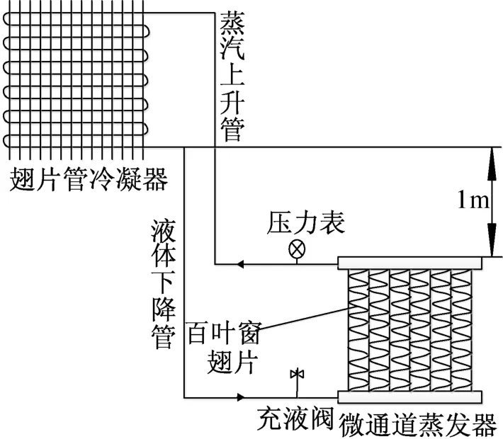
图1 分离式热管系统图Fig.1 System of the separate type heat pipe
蒸发器和冷凝器分别装有轴流风机,风机风量为2500 m3/h,风机总功率为260 W。蒸发器出风口通过风道与静压箱连接,在蒸发器和冷凝器进出口及中间部分共布置12个T型热电偶。冷凝器垂直气流方向每排水平布置12根管,沿气流方向为2排管,单管长800 mm,直管段之间由180°弯头连接而形成通路,管间距25 mm,错排布置,管径ϕ7×0.2 mm,翅片间距为2 mm,翅片厚度为0.15 mm。
微通道蒸发器由集流管、扁管、百叶窗翅片等组成,沿气流方向为1排管,共63个扁管,翅片上开有小百叶窗,其实物图和扁管规格如图2和图3所示。
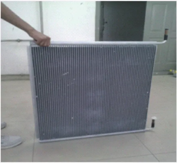
图2 微通道蒸发器实物图Fig.2 Microchannel evaporator
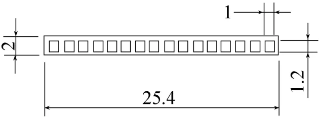
图3 扁管规格(mm)Fig.3 Flat tube specifications
微通道蒸发器采用百叶窗翅片能增加翅片表面对空气的扰动,破坏扁管表面空气流动的边界层,从而强化换热,有效提高系统能效。表1是在取得换热量相当的情况下,该微通道蒸发器与翅片管蒸发器的参数进行对比。
由表1可知,微通道蒸发器尺寸小、重量轻、成本低廉,不存在翅片管换热器上明显的电位腐蚀现象,而且由于产品结构上的创新,在高效节能、环保方面比铜材更具有优势。
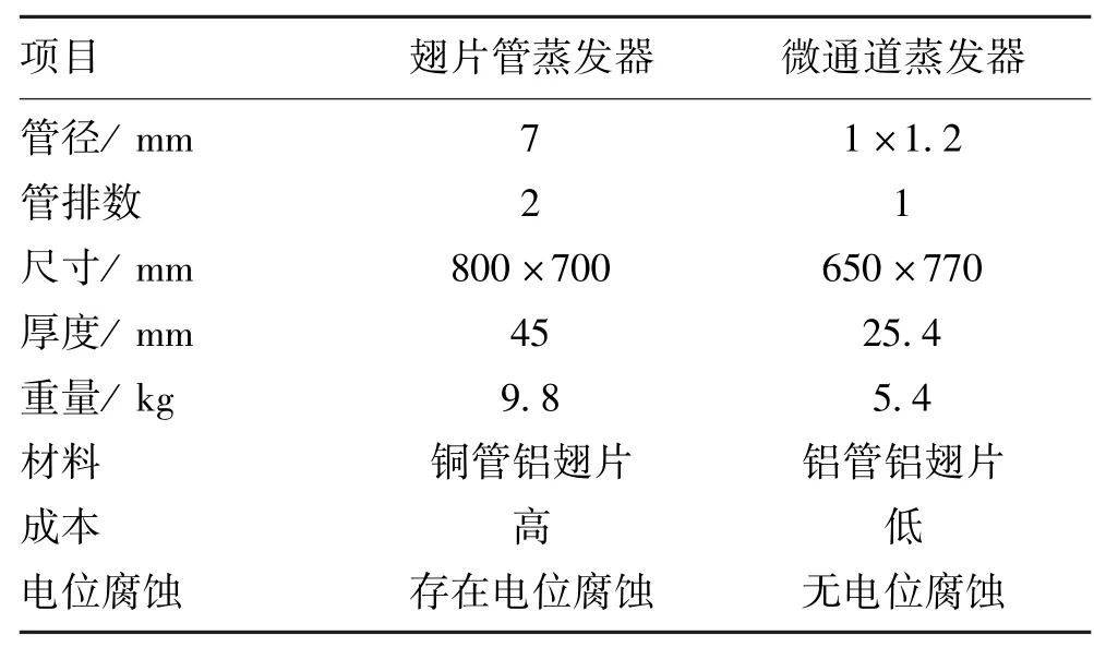
表1 微通道与翅片管蒸发器参数对比Tab.1 Parameters of Microchannel evaporator and copper fin evaporator
1.2 实验方法
本实验在焓差实验室进行,分离式热管的冷凝器和蒸发器分别放置在室外侧和室内侧,如图4和图5所示。实验装置采用工质 R22,依据 GB/T7725—2004《房间空气调节器》国家标准中的测试方法进行样机的性能测试,实验在名义制冷工况下进行。室内侧干湿球温度恒定,分别设置为27℃和19℃,室外侧干湿球分别设定为7℃/4.31℃、11℃/7.87℃、15℃/11.41℃、19℃/14.96℃和23℃/18.5℃共5个自由工况,充注量分别为1.7 kg、1.9 kg、2.1 kg、2.3 kg、2.5 kg、2.7 kg、2.9 kg和3.1 kg,根据充液率定义,对应充液率依次为80%、90%、100%、110%、120%、130%、140%和150%。根据测定的微通道蒸发器管壁温度分布、换热量和系统EER,并计算蒸发器的传热系数,确定最佳充液率。并在相同实验工况下,用翅片管蒸发器代替微通道型蒸发器进行了充注量实验研究。
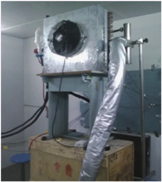
图4 室外侧冷凝器实物图Fig.4 Outdoor finned tube condenser
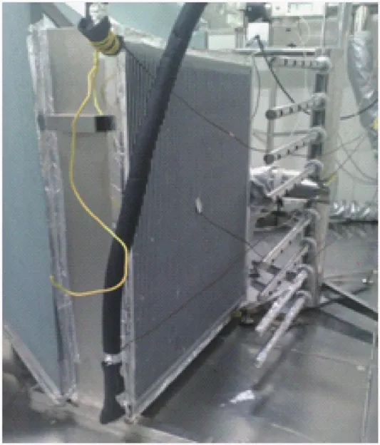
图5 室内侧微通道蒸发器实物图Fig.5 Indoor Microchannel evaporator
蒸发器的换热量Q的计算公式有:

式中:ρ为空气密度,kg/m3;ν为风速,m/s;A为风道截面积,m2;cp为空气定压比热容,kJ/kg;Δt为蒸发器进出风空气温差,℃。
2 实验结果与分析
在4~20℃的温差范围内,测定了各个充液率下微通道蒸发器的换热量,并进行了比较。从图6可以看出,在各个充液率下蒸发器换热量均随着室内外侧温差的增大而增大。充液率为120%的换热量比其他充液率下的制冷量都要大,充液率为120%时的换热量比充液率为 110%时的换热量平均提高13.84%,比充液率为130%时的换热量平均提高15.71%。
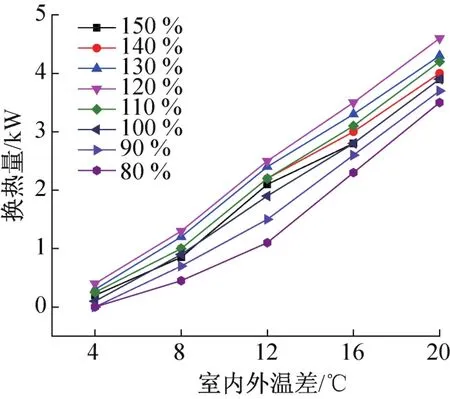
图6 不同充液率下的换热量比较Fig.6 Com parison of the heat transfer under different filling rate
在室内外温差为16℃时,不同充液率下微通道蒸发器换热量变化规律如图7所示。由图7可知,在充液率为80%~120%范围内,换热量随着充液率的增大而逐渐增加,充液率为120%时换热量达到最大值3489 W;当充液率超过120%时,随着充液率的增加,换热量减小。这是因为当充液率较小时,蒸发器内部过多的工作面在进行与过热蒸汽之间的显热交换,随着充液率的增加,与液相工质接触的工作面面积逐渐增加,换热得到逐步强化;充液率高于120%时,蒸发器入口处液态工质容易出现过冷现象,蒸发器底部不处于相变换热区,影响蒸发器的传热性能,如果继续增大充液率,蒸发器将会只处于液相区,分离式热管将无法工作。在120%充液率情况下,蒸发器进口温度为20.5℃,中间部分的温度为22.1℃,出口温度为23.2℃,整个蒸发器表面温度变化不大,蒸发器大部分工作面处在相变换热区,蒸发器换热量达到最大值,所以该分离式热管的最佳充液率范围在120%左右。

图7 换热量随充液率的变化Fig.7 Variation of heat transfer with filling rate
图8和图9为在室内外温差为16℃时,不同充液率下分离式热管系统的EER和蒸发器传热系数的变化规律。由图8~图9可知,随着蒸发器充液率的提高,EER和换热系数均经历了一个先增大后减小的过程,充液率过低或过高,蒸发器的相变换热面积均会减小,使传热系数下降。在充液率达到120%时,EER达到最大值为13.76,此分离式热管仅有室内外机上的两个风机消耗电能,所以EER要明显高于常规的空调,具有很好的节能性。
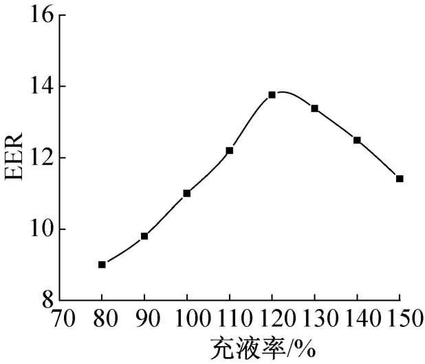
图8 EER随充液率的变化Fig.8 Variation of EER with filling rate
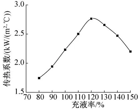
图9 换热系数随充液率变化Fig.9 Variation of heat transfer coefficient with filling rate
在相同的实验工况下,对翅片管蒸发器进行了充注量实验研究。在充注量为5.2 kg时,对应充液率为97%,其换热量达到最大为3577,EER为13.39。以微通道换热器作为蒸发器,与翅片管蒸发器相比较,体积减小,重量减轻45%,系统工质充注量降低51.9%,系统EER提高2.8%。
在工质特性、热输入量及充液率相同的情况下,与翅片管蒸发器相比较,微通道蒸发器具有结构紧奏、流体通道直径小,换热效率高等特点,所以其管内出口段更容易出现过热蒸汽,从而影响换热。为保证微通道蒸发器处于最佳的换热性能,所以采用微通道蒸发器的分离式热管最佳充液率要比采用翅片管蒸发器的略大。
3 结论
本文采用微通道换热器作为分离式热管的蒸发器,实验研究了在不同充液率下分离式热管的传热性能,得出以下主要结论:
1)在室内外温差为4~20℃的范围内,微通道蒸发器的换热量随着室内外侧温差的增大而增大;分离式热管的最佳充液率在120%左右,在室内外温差为16℃时,EER可以达到13.76。
2)在换热量相当的条件下,与翅片管蒸发器相比较,微通道换热器作为蒸发器,体积减小,重量减轻45%,工质充注量降低51.9%,系统EER提高2.8%,在节能环保方面具有很大优势。
[1] 金鑫,瞿晓华,祁照岗,等.分离式热管型机房空调性能实验研究[J].暖通空调,2011,40(9):133⁃136,73.(Jin Xin,Qu Xiaohua,Qi Zhaogang,et al.Perform⁃ance experiment of separate heat pipe air conditioning units for electronic equipment rooms[J].Journal of HV&AC,2011,41(9):133⁃136,73.)
[2] Zheng Y,Li Z,Liu X,et al.Retrofit of air⁃conditioning system in data center using separate heat pipe system [C]//Proceedings of the 8th International Symposium on Heating,Ventilation and Air Conditioning,Berlin Heidel⁃berg:Springer,2014:685⁃694.
[3] Kuang Y W,Wang W,Zhuan R,et al.Simulation of boil⁃ing flow in evaporator of separate type heat pipe with low heat flux[J].Annals of Nuclear Energy,2015,75:158⁃167.
[4] Tang Z,Liu A,Jiang Z.Two phase flow and heat transfer characteristics of a separate⁃type heat pipe[J].Heat and Mass Transfer,2011,47(7):841⁃846.
[5] Liu X,Fang G Y,Chen Z.Condensation heat transfer characteristics of a separate heat pipe in cool storage air⁃conditioning systems[J].Chemical Engineering&Tech⁃nology,2011,34(3):415⁃421.
[6] Zhu D D,Yan D,Li Z.Annual energy⁃using simulation of separate heat⁃pipe heat exchanger[C]//12th Conference of International Building Performance Simulation Association Building Simulation,Sydney,Australia:International Build⁃ing Performance Simulation Association,2011:1168⁃1174.
[7] 庄俊,张红.热管技术及其工程应用[M].北京:化学工业出版社,2000.
[8] 洪光,张春辉,罗晴,等.常温小温差下的分离式热管换热器充液率研究[J].节能,2011(1):24⁃27.(Hong Guang,Zhang Chunhui,Luo Qing,et al.Experimental study on optimal liquid filling ratio of separate heat pipe under a small temperature difference[J].Energy Conser⁃vation,2011(1):24⁃27.)
[9] 汤广发,刘娣,赵福云,等.分离型热管充液率运行边界探讨[J].湖南大学学报(自然科学版),2005,32 (1):63⁃68.(Tang Guangfa,Liu Di,Zhao Fuyun,et al. Research on the envelope of initial filling ratio for separate heat pipe[J].Journal of Hunan University(Natural Sci⁃ences),2005,32(1):63⁃68.)
[10]Pai P F,Peng H,Ma H.Thermomechanical finite⁃element analysis and dynamics characterization of three⁃plug oscilla⁃ting heat pipes[J].International Journal of Heat and Mass Transfer,2013,64:623⁃635.
[11]Habeebullah M H,Akyurt M,Najjar Y S H,et al.Exper⁃imental performance of a waste heat recovery and utilization system with a looped water⁃in⁃steel heat pipe[J].Applied Thermal Engineering,1998,18(7):595⁃607.
[12]Rahmat M,Hubert P.Two⁃phase simulations of micro heat pipes[J].Computers&Fluids,2010,39(3):451⁃460.
[13]郝莹,臧润清,金育义.以R600A为工质的分离式热管的实验研究[J].低温与超导,2009,37(12):37⁃41.(Hao Ying,Zang Runqing,Jin Yuyi.Experimental research of separated heat pipe using R600A as working fluid[J].Cryogenics and Superconductivity,2009,37 (12):37⁃41.)
[14]安翔.二氧化碳热管最佳充液率实验研究[J].煤气与热力,2012,32(6):9⁃11.(An Xiang.Experimental study on optimal liquid filling ratio of carbon dioxide heat pipe[J].Gas&Heat,2012,32(6):9⁃11.)
[15]陈岚,苏俊林,伍贻文.分离式热管充液率实验研究[J].上海理工大学学报,2003,25(3):285⁃288. (Chen Lan,Su Junlin,Wu Yiwen.Experimental study on the working fluid filling rates of a special separate type heat pipe[J].Journal of University of Shanghai for Science and Technology,2003,25(3):285⁃288.)
[16]朱玉琴,李迓红.分离式热管小倾角蒸发段传热特性的试验研究[J].西安石油大学学报(自然科学版),2006,21(1):51⁃53.(Zhu Yuqin,Li Yahong.Experi⁃mental study on the performances of the heat transfer of the small dip⁃angle evaporation segment of a separate⁃type heat pipe[J].Journal of Xi’an Shiyou University(Natural Sci⁃ence Edition),2006,21(1):51⁃53.)
[17]鲁红亮,陶红歌,胡云鹏.平行流换热器中热流体分布均匀性的研究进展[J].制冷学报,2010,31(6):39⁃45.(Lu Hongliang,Tao Hongge,Hu Yunpeng.State⁃of⁃the⁃art of thermo⁃fluid uniform distribution in microchannel heat exchanger[J].Journal of Refrigeration,2010,31 (6):39⁃45.)
[18]赵宇,祁照岗,陈江平.微通道平行流蒸发器流程布置研究与分析[J].制冷学报,2009,30(1):25⁃29. (Zhao Yu,Qi Zhaogang,Chen Jiangping.Flow configura⁃tion in micro⁃channel parallel flow evaporator[J].Journal of Refrigeration,2009,30(1):25⁃29.)
[19]张剑飞,秦妍,孔祥国.扁管和百叶窗式微通道换热器空气侧阻力的实验研究[J].制冷学报,2014,35(1):88⁃91.(Zhang Jianfei,Qin Yan,Kong Xiangguo.Experi⁃mental study of the air resistance of microchannel heat ex⁃changer with flat tube and louver fin[J].Journal of Refrig⁃eration,2014,35(1):88⁃91.)
[20]金育义,臧润请,顾永明.分离式热管在不同高度差下传热性能的实验研究[J].应用能源技术,2009(4):45⁃47.(Jin Yuyi,Zang Runqing,Gu Yongming.Experi⁃mental investigation of heat transferring capacity of separate type heat pipe which under different level difference[J]. Applied Energy Technology,2009(4):45⁃47.)
胡张保,男,讲师,郑州轻工业学院建筑环境工程学院,15937175611,E⁃mail:huzhangbao@zzuli.edu.cn。研究方向:制冷低温设备研制与开发。
About the corresponding author
Hu Zhangbao,male,lecturer,School of Architecture and Envi⁃ronmental Engineering,Zhengzhou University of Light Industry,+86 15937175611,E⁃mail:huzhangbao@zzuli.edu.cn.Re⁃search fields:development in refrigeration and cryogenics.
Experimental Study on the Working Fluid Filling Rates of Microchannel Evaporator in a Special Separate Type Heat Pipe
Hu Zhangbao1Zhang Zhiwei2Jin Tingxiang2Shao Shuangquan3Zhang Hainan3
(1.School of Building Environment Engineering,Zhengzhou University of Light Industry,Zhengzhou,450002,Chi⁃na;2.School of Energy and Power Engineering,Zhengzhou University of Light Industry,Zhengzhou,450002,Chi⁃na;3.Technical Institute of Physics and Chemistry,CAS,Beijing,100190,China)
Water The microchannel heat exchanger was used as the evaporator of a separated type heat pipe,and the working fluid filling rate of the separate type heat pipe was studied experimentally when the filling rate changed from 80%to 150%.The heat transfer,the wall tem⁃perature of microchannel evaporator and the EER of the system were measured.The heat transfer characteristics under different filling rate were analyzed respectively,and the heat transfer coefficient was calculated.The results show that the heat transfer increased with the tem⁃perature difference between the indoor air and the outdoor air.The optimal filling rate was about 120%.Moreover,the microchannel e⁃vaporator was compared experimentally with the finned tube evaporator under the condition of same heat transfer.The weight and the re⁃frigerant charge of the microchannel evaporator is 45%and 15.9%lower than that of the finned tube evaporator,respectively.The EER of the system with the microchannel evaporator is 2.8%higher than that of the system with the finned tube evaporator.
eparated type heat pipe;microchannel heat exchanger;filling rate
TB657.5;TQ051.5
A
0253-4339(2015)04-0098-05
10.3969/j.issn.0253-4339.2015.04.098
简介
国家科技支撑计划(2012BAA13B03_02_4)资助项目。(The project was supported by the Key Technologies R&D Program of China(No. 2012BAA13B03_02_4).)
2014年12月16日

