Elastodynamic Analysis of Thick Multilayer Composite Plates by The Boundary Element Method
J.Usecheand H.Alvarez
Elastodynamic Analysis of Thick Multilayer Composite Plates by The Boundary Element Method
J.Useche1and H.Alvarez1
Dynamic stress analysis of laminated composites plates represents a relevant task in designing of aerospace,shipbuilding and automotive components where impulsive loads can lead to sudden structural failure.The mechanical complexity inherent to these kind of components makes the numerical modeling an essential engineering analysis tool.This work deals with dynamic analysis of stresses and deformations in laminated composites thick plates using a new Boundary Element Method formulation.Composite laminated plates were modeled using the Reissner’s plate theory.We propose a direct time-domain formulation based on elastostatic fundamental solution for symmetrical laminated thick plates.Formulation takes into account the rotational inertia of the plate.Domain integrals related to distributed body forces and those related to inertial terms are evaluated using the Radial Integration Method.Contour integrals are numerically evaluated using quadratic approximation for displacements and generalized forces.Time integration is performed using the Houbolt Integration Method.Resulting shear forces and bending moments are calculated.The results obtained using this formulation show good agreement when compared with finite element solutions.
Boundary element method,Laminated thick plates,Dynamic stress analysis,Radial integration method,Composite plates.
1 Introduction
Laminated composite plates have gained popularity for the manufacturing of components with high strength to weight ratio and superior performance in highly demanding environments.These characteristics have become an attractive alternative in the marine,automotive,mechanical,civil and aerospace industries[Vasiliev and Morozov(2001)].In general,composites have complex mechanical responses not found in isotropic materials and no closed solutions to mathematical models arepossible,being necessary the use of numerical modeling for practical engineering analysis.
The Finite Element Method(FEM)is a well established technique for numerical modeling of complex composite plate structures under dynamic loads[Reddy(2004);Tenek and Argyris(2010);Reddy,Roman,Arciniegas,and F.(2010)and Zhang and Atluri(1986)].However,FEM analysis of structures involving geometrical discontinuities or high stress concentrators requires the use of meshes with high number of finite elements.In this way,the computational cost of the models is increased[Bathes(2007)].
The Boundary Element Method(BEM)has emerged as an attractive option to the FEM for the analysis of plates and shells structures[Mukherjee(2013);Wrobel and Aliabadi(2002);Rashed(2000);Dirgantara and Aliabadi(1999);Wen,Aliabadi,and Young(2000a);Beskos(2003)and Providakis and Beskos(1999)].Since BEM only requires the discretization of the boundary of the body under analysis the number of unknowns in a model is reduced.This feature makes BEM an attractive tool for the analysis of problems with high stress gradients,geometric discontinuities and in finite domains.Moreover,BEM has been successfully used in the static and dynamic analysis of laminated plates[E.L.Albuquerque and Aliabadi(2006);E.L.Albuquerque and de Paiva(2007);W.Portilho de Paiva and Albuquerque(2011)and Wang(1991)].In spite of this,BEM hasn’t been applied to dynamic stress analysis of thick laminated composite plates.This problem represents an attractive field of research that would contribute to the advancement of knowledge in computational structural mechanics.
Three different BEM formulations could be used in dynamic plate analysis:direct time-domain formulations using elasto-static fundamental solutions[Gao(2002);Partridge,Brebbia,and Wrobel(1992);Manolis and Beskos(1998);Sapountzakis(2010),Perez-Gavilán and Aliabadi(2001)and Katsikadelis(2014)];formulations based on elasto-dynamics fundamental solutions[Wen and Aliabadi(2006)and Wen,Adetoro,and Xu(2008)]and formulations based on Laplace or Fourier transformations of governing equations[Duddeck(2010)and Wen,Aliabadi,and Young(2000b)].Compared to elastodynamic fundamental solutions,the use of elastostatic fundamental solutions in BEM formulations presents the advantage of mathematical simplicity,thus allowing the application of well established methods to treat domain integrals[Providakis and Beskos(1999)].Formulations based on elasto-static fundamental solutions have been successfully used for dynamic BEM analysis of isotropic plates and shells[Useche and Albuquerque(2012);Useche,Albuquerque,and Sollero(2012)and Useche(2014)].Unlike to formulations using elasto-dynamic fundamental solutions,BEM formulations based on the use of elasto-static solutions generate systems of equations not involving time or frequen-cy.Moreover,domain integrals related with inertial terms do not need to be transformed to the boundary.This aspect represents a major advantage because calculation of boundary integrals in elasto-dynamic formulations is expensive[Gaul,Kogl,and Wagner(2003)].
In this paper a direct Boundary Element Method formulation for the dynamic transient analysis of symmetric laminated thick plates is presented.Formulation is based on the elastostatic fundamental solutions proposed by[Wang(1991)].Plates were analyzed using the First Order Shear Deformation Theory(FSDT)for laminated composite plates[Reddy(2004)].Formulation takes into consideration effects of rotatory inertia.Integrals related to domain loads and inertial forces were calculated using the Radial Integration Method.The proposed formulation is validated through numerical tests and results are compared with FEM solutions.
2 Laminated plate equations
Consider a symmetrically laminated plate occupying an area Ω in thex1x2plane with total thicknesshand composed byNorthotropic layers.Each layer has principal material coordinates orientated at an angleθreferred to the laminated coordinatex1.Thex1x2plane is considered the midsurface andx3-axis is taken normal to this surface.Plate is bounded by the contourThe FSDT was employed to model the bending response for the plate.In the FSDT,relations between generalized displacements and strains are given by[Wrobel and Aliabadi(2002)]:

whereχαβandψαare the curvature tensor and the transversal shear strains,respectively.In this work,indicial notation and the Einstein’s summation convention are used.In these equations,wαdenotes in-plane rotations andw3represents transversal deflection.
Dynamic equilibrium equations for a plate are given by[Useche,Albuquerque,and Sollero(2012)]:

whereqαare distributed in-plane moments andq3=pis the distributed pressure,Λikis the inertial tensor de fined as: Λαβ=1/12ρh3δαβ,Λ33=ρhand Λα3=Λ3α=0,MαβandQαare the resultant tensor moment and the normal shear vector,respectively,wα,ttdenotes angular in-plane accelerations andw3,ttis the transverse acceleration.For laminated plates,MαβandQαare given by[Wang(1991)]:
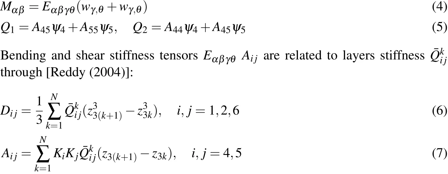
whereNis the number of layers,KiandKjare the shear correction factors.TensorEαβγθis related toDijthrough Voigt notation.
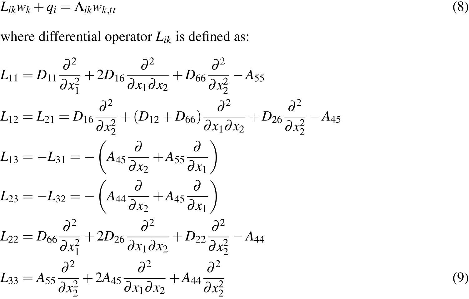
Substituting(4)and(5)into(2)and(3),we obtain the following set of differential equations:
3 Integral formulation
The boundary integral formulation of equations(8)is derived by using the weighted residual method and making use of the Green’s identity[Wrobel and Aliabadi(2002)].In this way,the integral formulation for these equations is given by:

withqα=0.In this equation,are fundamental solutions of the orthotropic shear deformable plates[Wang(1991)];cij(x′)are the jump terms.The stress integral formulation is obtained by substituting(10)into(1)and then into(2)and(3).The derivatives of the generalized displacements are calculated as:

The above formulation requires the calculation of domain integrals related with distributed load and inertial terms.Diverse methods have been developed for the calculation of such integrals[Wrobel and Aliabadi(2002)].Among of them,the Radial Integration Method(RIM),the Cell Integration Method(CIM)and the Dual Reciprocity Method(DRM)are the most used in BEM analysis.Although CIM is a simply and well established method,it requires discretization domain thus eliminating the main BEM advantage.DRM has proven to be a very successful and efficient method to transform domain integrals in dynamic BEM analysis of plates and shells[Useche and Albuquerque(2012);A.Sahli and Rahmani(2014);Wen and Aliabadi(2000)and Fata(2012)].The main disadvantage of DRM lies on finding particular solutions to governing differential equations(1),which in general is a cumbersome task.Compared with DRM,RIM has been widely used in BEM as it is applicable to any kind of problem regardless of the complexity of the used fundamental solutions[Wrobel and Aliabadi(2002)and E.L.Albuquerque and de Paiva(2007)].In the present work,the Radial Integration Method(RIM)is used as presented in[W.Portilho de Paiva and Albuquerque(2011)].
Consider the domain termq3(t)in equation(10)approximate over the domain as a sum of theMproducts between radial basis functionsfmand unknown coefficientsγm(t),that is(see figure 1):

Applying RIM to the second domain integral in(11),we obtain[Useche,Albu-
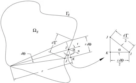
Figure 1:Transformation of domain integral through Radial Integration Method
querque,and Sollero(2012)]:

whereris the value ofρin a point of the boundary Γ as shown in figure 1.In this expressionis de fined as:

The approximation functionsfmare taken asfm=1+rm,wherermrepresents the distance between the center of the radial basis function and the integration point.Coefficientsγm(t)are related topm(t)through expression:

whereFikis a matrix of coefficients obtained by taking the value ofp(t)at different RIM points.
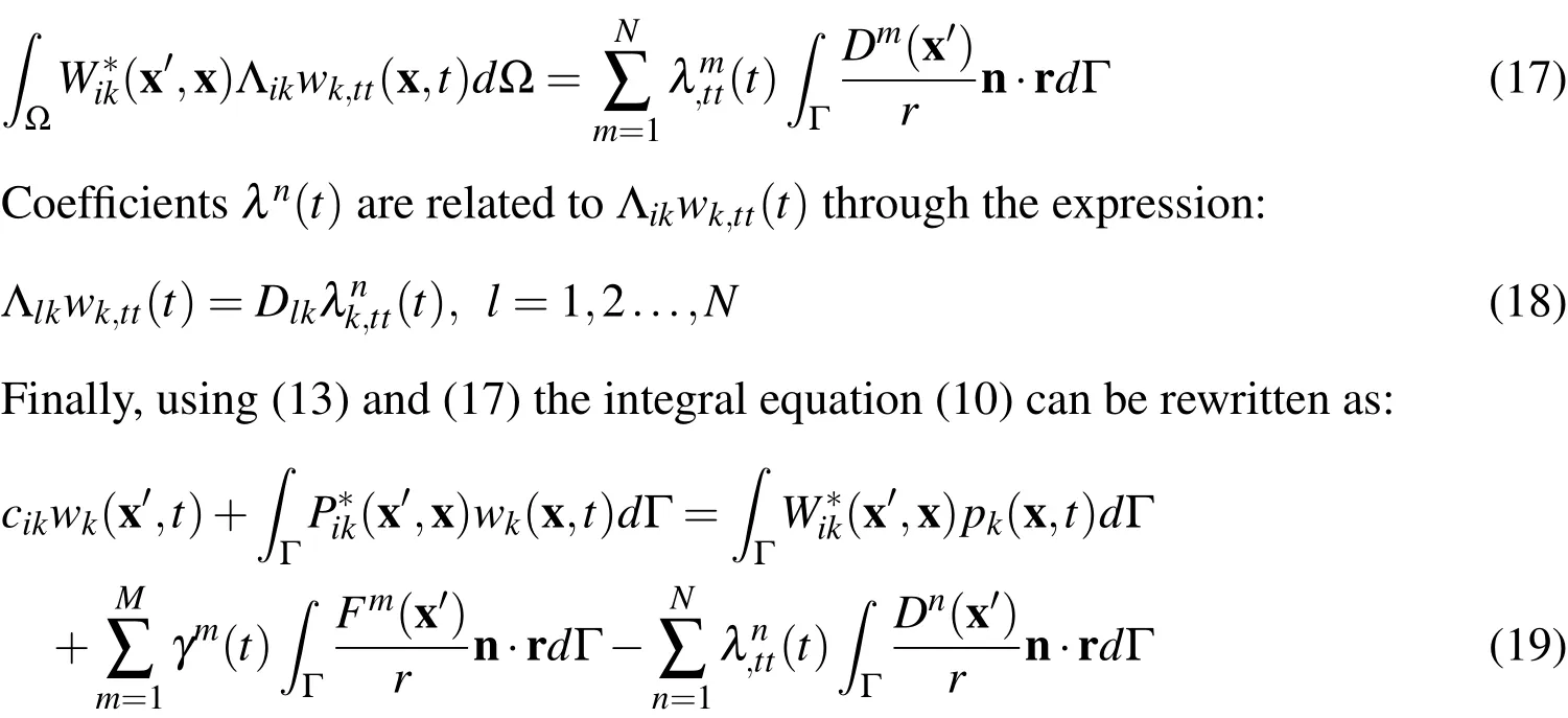
On the other hand,integral related with the inertial term in(10)can be transformed to the boundary.For this,consider the following approximation for Λikwk,tt:

wheredn=rmlog(rm)andare unknown coefficients.Thus,third integral in equation(10)is rewritten as:
4 Boundary element formulation
In order to approximatewkandpk,quadratic discontinuous boundary elements were used.The geometry of the boundary is approximated through continuous quadratic elements.In this way,for a given collocation pointi,equations(19)can be discretized as:
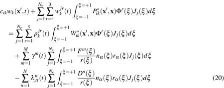
whereJrepresents the Jacobian of the transformation(dΓ =J(ξ)dξ);ξis the element local coordinate and Φris the shape function of the element.Expression forγm(t)andare obtained by inverting(15)and(18)and replaced into equation(20).Applying this equation at each collocation point successively,we obtain a set of equations that can be expressed in matrix form as:

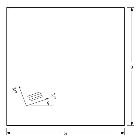
Figure 2:Square square plate
5 Time-integration scheme
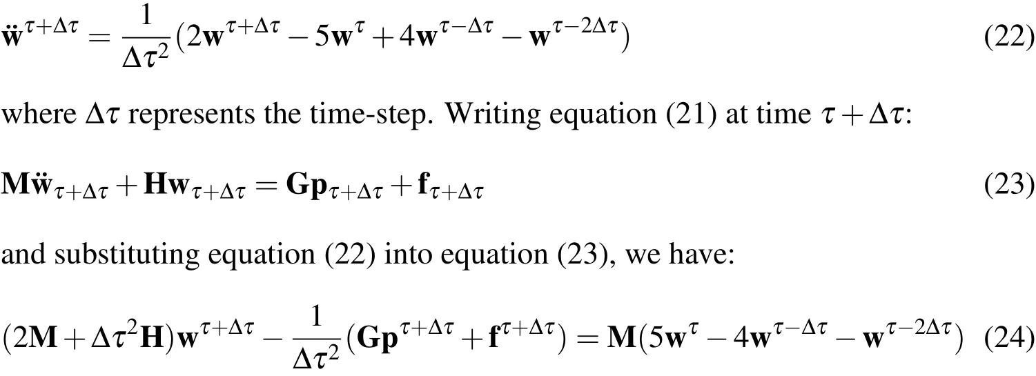
The ordinary differential equation(21)is solved by using the Houbolt time-integration algorithm.Houbolt method has been successfully used in the dynamic BEM analysis of plates and shells in[Useche and Albuquerque(2012);Useche,Albuquerque,and Sollero(2012);Partridge,Brebbia,and Wrobel(1992)and Gaul,Kogl,and Wagner(2003)].In this method,the acceleration vector¨w at timeτ+Δτis approximated as[Useche(2014)]:
6 Numerical examples
The proposed formulation was initially tested considering a simply supported square quasi-isotropic plate(as presented in figure 2)under a constant impulsiveq3=100
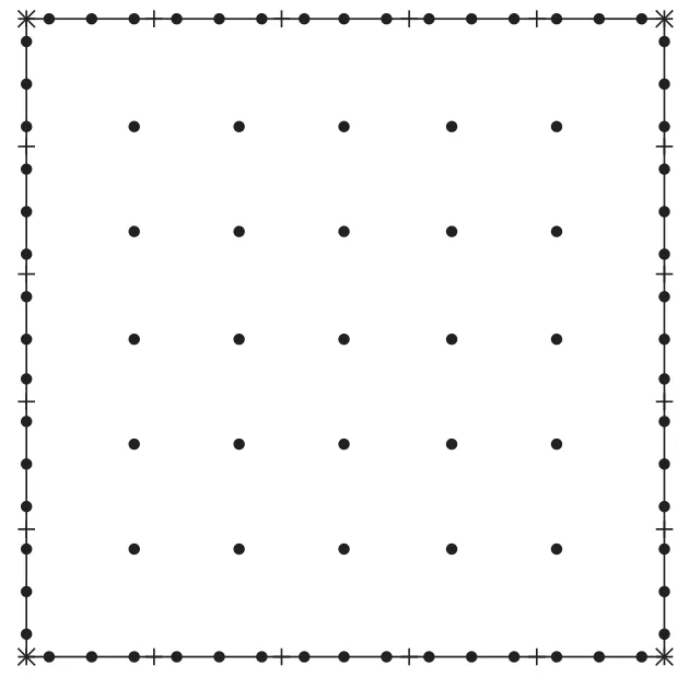
Figure 3:Boundary element model for square plate
N/cm2.The dimensions of the plate are:a=b=10 cm,h/a=10 with elastic constantsE1/E2=1.001,E1=210×105N/cm2,ν=0.3 and mass densityρ=0.7853 N.s2/cm4.Boundary conditions employed are:w3=0andMn=0 on all sides of the plate.The dynamic response of the plate was obtained for the intervalt∈[0,0.03]and using 9,16 and 49 RIM collocations points as shown in figure 3.
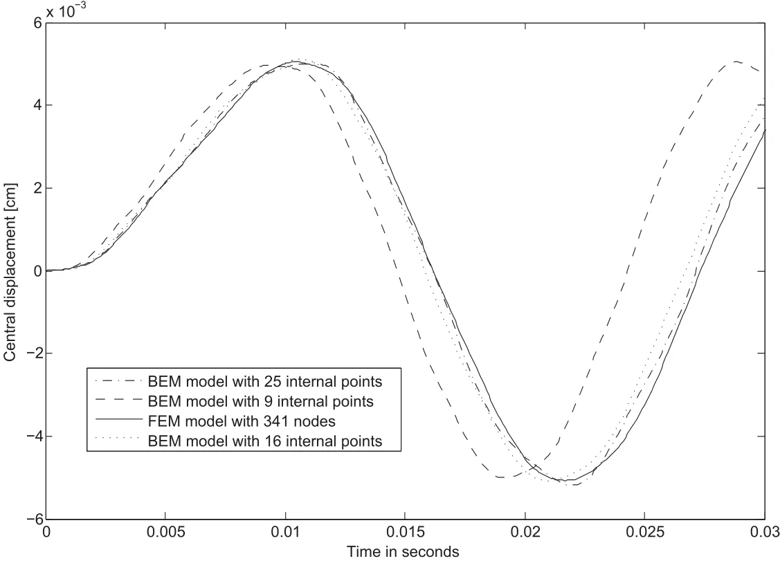
Figure 4:Transversal displacement for the square plate as function of RIM points
A FEM analysis using the ANSYS®code was carried out in order to validate the BEM solution.FEM model is based on SHELL93 shear deformable finite element.
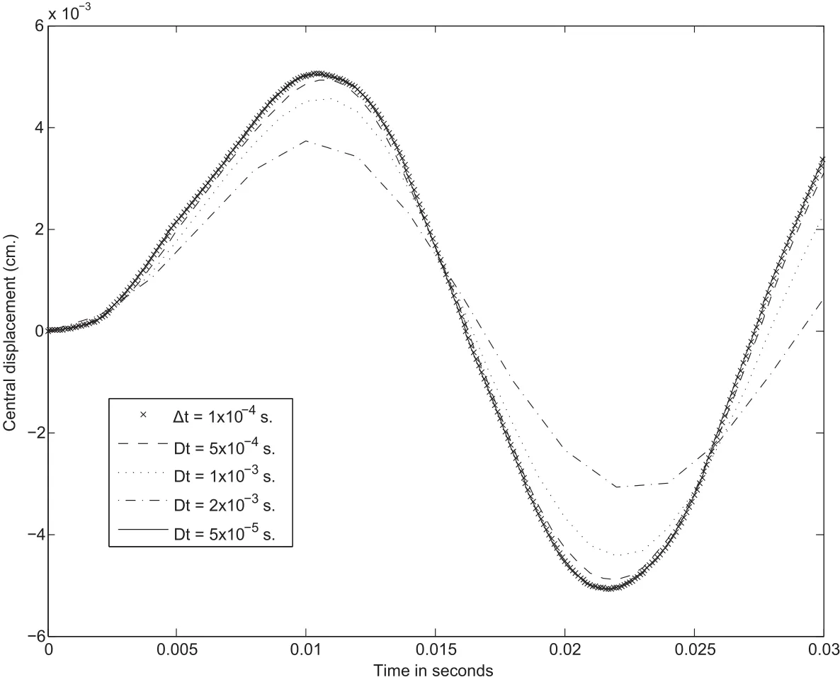
Figure 5:Convergence of the central transversal displacement versus time-step for 49 RIM points
Figure 4 shows the central deflection for different BEM meshes compared with the FEA solution.In this analysis a time step Δt=1.0×10⁻⁴s.is used.On the other hand,a BEM model with 49 RIM collocation points is used to carrie out a convergence analysis for the central deflection versus time step.Figure 5 depicts the history of convergent maximum deflection for different time steps.As results show,the BEM formulation gives good results when compared with FEM solutions.Now,consider a three layer orthotropic[0/90/0°]clamped square plate with length of 25 cm and thickness 5 cm,is subjected to suddenly distributed impulsive load q=10 N/cm2.The material properties used for each layer are:E1/E2=25,E2=2.1×106N/cm2,G12=G13=G23=0.5E2,ν12=0.25 andρ=8×10⁻⁶N-sec2/cm4.As in previous example,in order to compare results,a FEM analysis is performed.Convergence solutions for central displacement and bending moments under static load is presented in table 1.Good agreement is observed when FEM solutions are compared with analytical solutions[Reddy(2004)].Figure 6 shows convergent dynamic solutions for bending moments at center of the plate.A convergent solution was obtained using a FEM mesh with 9216 elements.
Figure 7 depicts the history of vertical central deflection for time interval from 0 to 750µs for Δτ=5µs using 145,421,571 and 691 RIM collocation points.
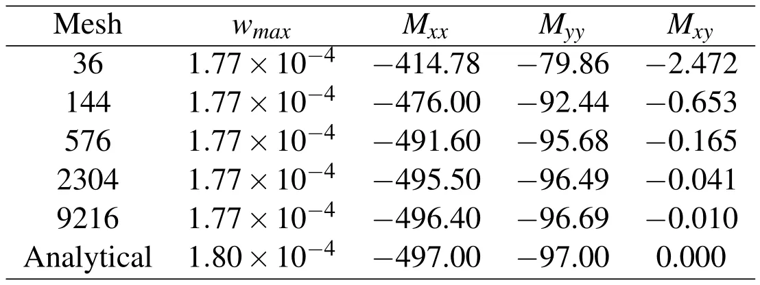
Table 1:Finite element convergence analysis for static conditions
Figure 8 shows convergence solution for resultant bending moments at center of the plate.Good agreement of BEM results when compared with the FEM solution is observed.
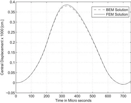
Figure 7:Central deflection for[0/90/0°]clamped square plate
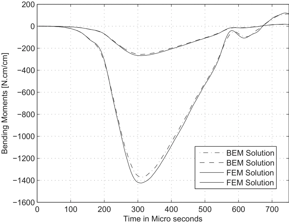
Figure 8:Bending moments for[0/90/0°]clamped square plate
Figure 9 shows the central deflection of a four-layer orthotropic[0/90/90/0°]simply supported plate under suddenly applied pulse loading q=10 N/cm2.Plate has same dimensions and material properties as previous one.Figure 10 shows convergent bending moments at the center of the plate for this time interval.Both central deflection and bending moments obtained with BEM formulation show good agreement when compared with FEM solution.
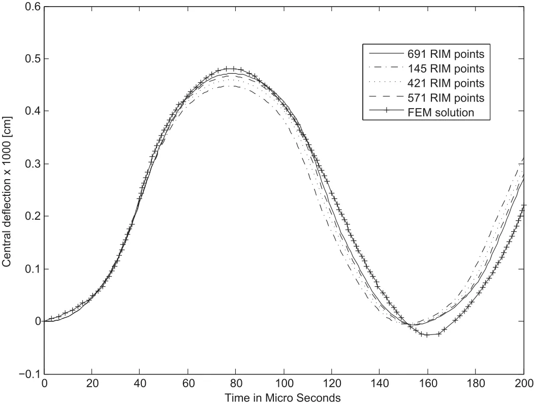
Figure 9:Central deflection for[0/90/90/0°]clamped square plate
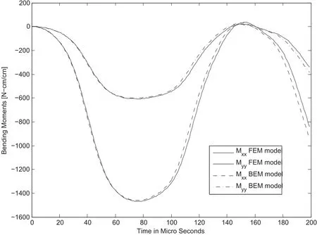
Figure 10:Bending moments for[0/90/90/0°]clamped square plate
In this example a full clamped rectangular plate made of Glass Laminate Aluminum Reinforced Epoxy(GLARE)with a central rectangular hole(as presented in figure 11)is analyzed.Rectangular plate has dimensions:a/b=c/d=1.5,a/c=3 and thicknessh=0.14 cm.Plate was tested with 5-layered aluminum alloy/glass reinforced plastic material,with 2 layer of aluminium(0.03 cm thickness each)and 3-layersofcompositeconstituentS2-glass fibres/epoxymatrix(0.025mmeach)us-ing the sequence:[GF/AL/GF/AL/GF](GF:glass fiber,AL:Aluminum).Mechanical properties of these materials are:Aluminum layersE=92.39×10⁵N/cm2,density:ρ=2.7×10-5N-s2/cm4,Poisson ratioν=0.33.For glass fiber composite layer-cross plied,we have:E1=31.17×10⁵N/cm2,E2=31.17×105N/cm2,G12=G13=G23=5.548×105N/cm2,ν12=0.098,ν13=ν23=0.0575 and densityρ=2.0×10⁻⁵N-s2/cm4.
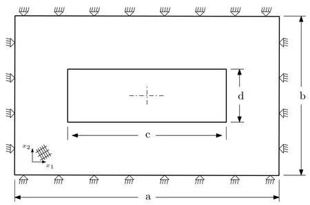
Figure 11:Simply supported rectangular plate with rectangular hole
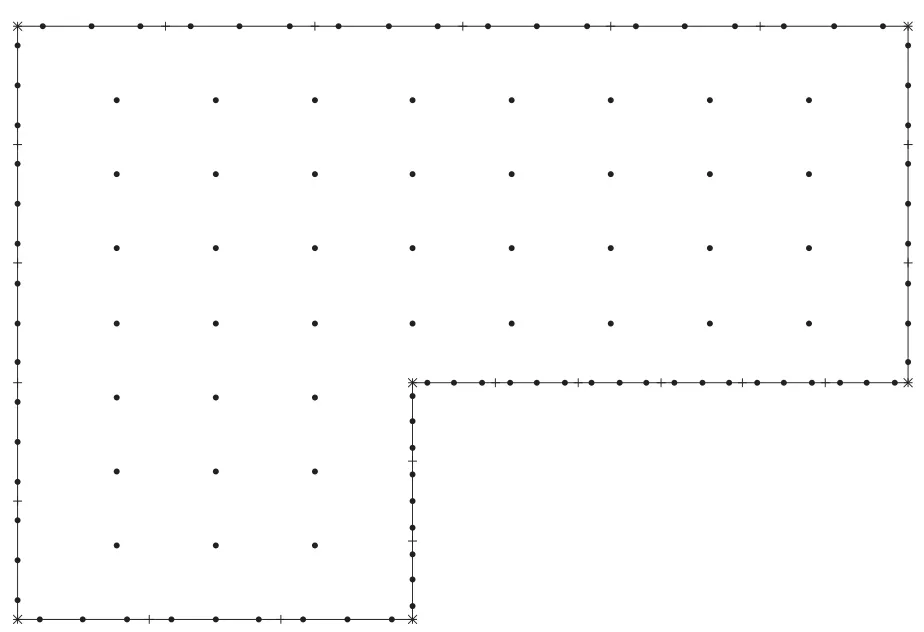
Figure 12:One-quarter BEM model for plate with rectangular hole
In this analysis,BEM model with 41 internal points and 26 elements,as presented in figure 12,is used.Figure 13 shows a comparison between BEM and FEM convergent bending moments at the center of the plate.Good agreement is observed between BEM and FEM solution.
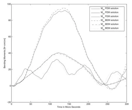
Figure 13:Bending moments for GLARE composite plate
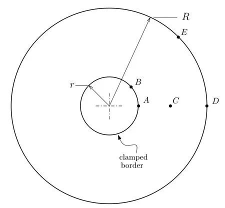
Figure 14:Simply supported circular plate with central hole
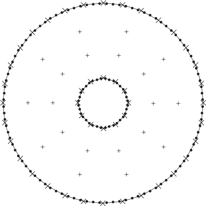
Figure 15:BEM model for circular plate with central hole
Finally,Figure 14 shows a six layer orthotropic[0/45/-45°]sclamped circular plate with a central hole.BEM model is presented in figure 15.Dynamic response of this plate is analyzed for impulsive pressure load presented in figure 16 and given For this plate,R/r=2 and thicknessh=R/100 cm.Materials properties used for each layer are:E1=52.5 N/cm2,E2=2.1×106N/cm2,G12=G13=G23=1.1 N/cm2ν12=0.25 andρ=8×10⁻⁶N-sec2/cm4.
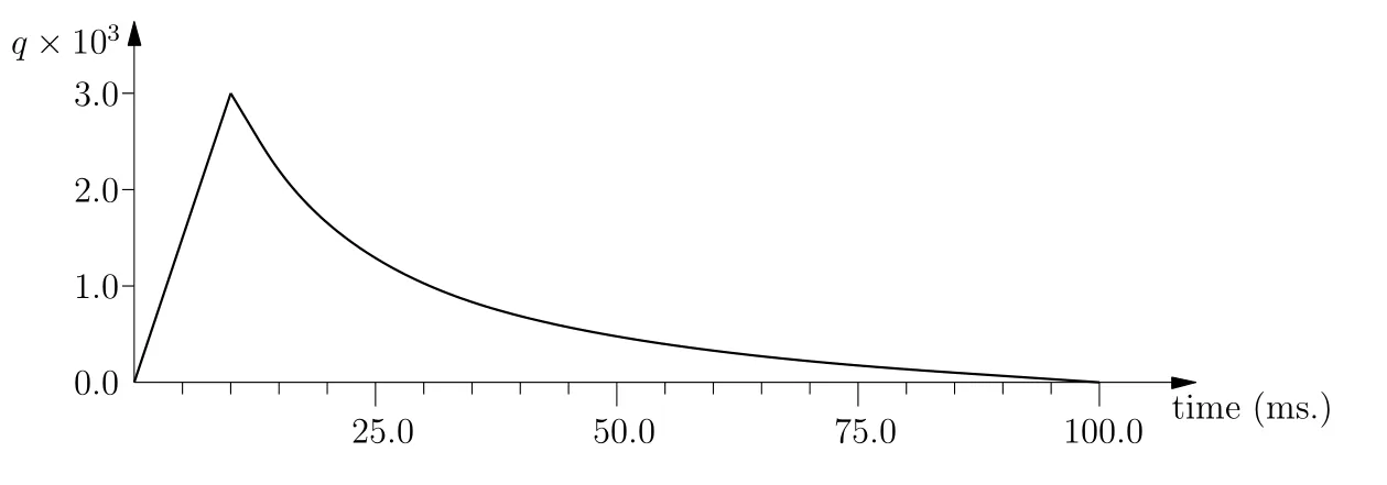
Figure 16:Impulsive load function for circular plate problem
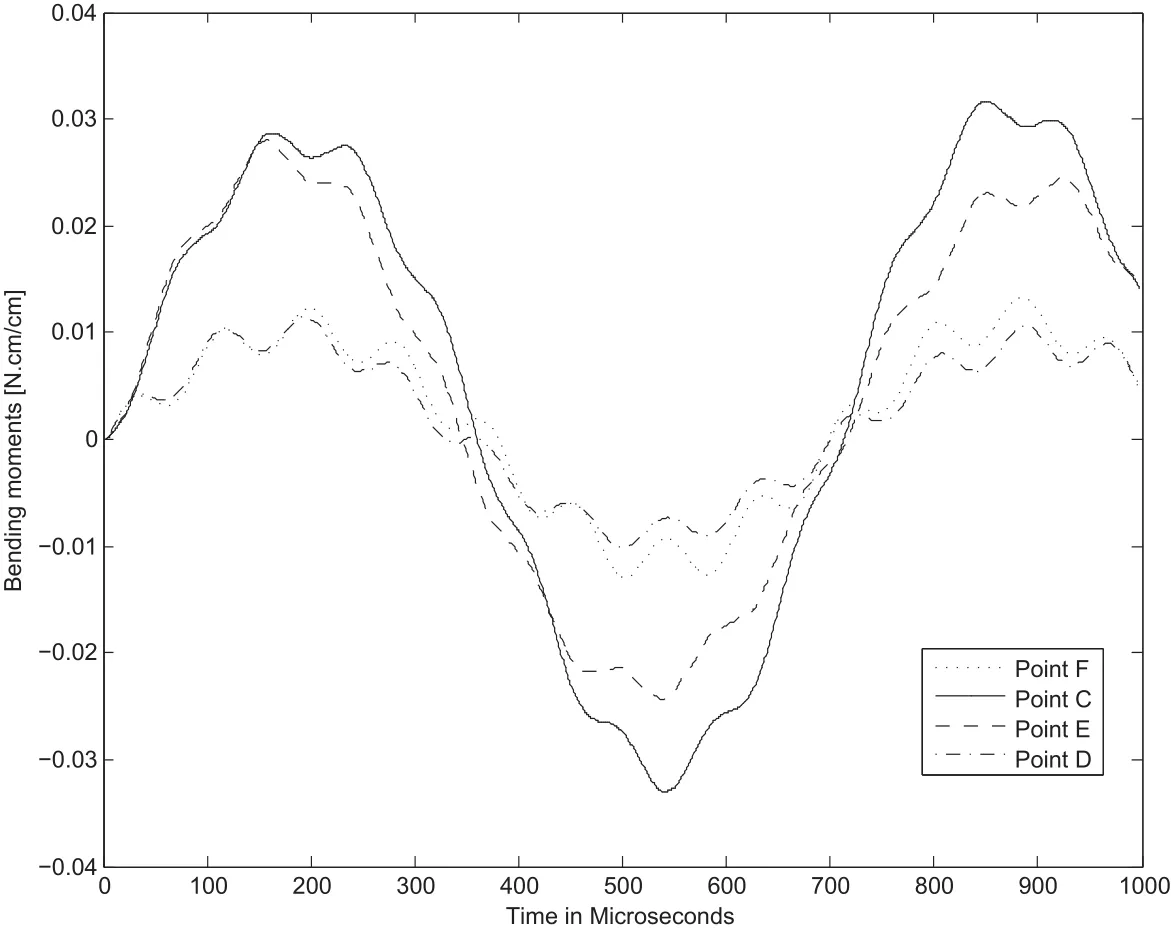
Figure 17:Deslacements at points C,D,E and F for circular plate

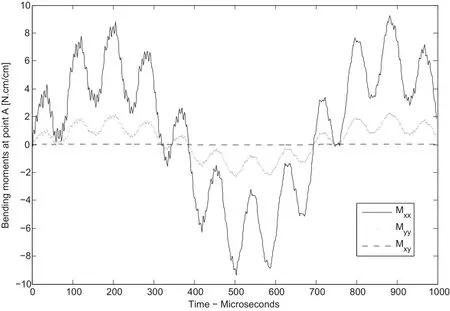
Figure 18:Bending resultant stress at point A for circular plate with hole
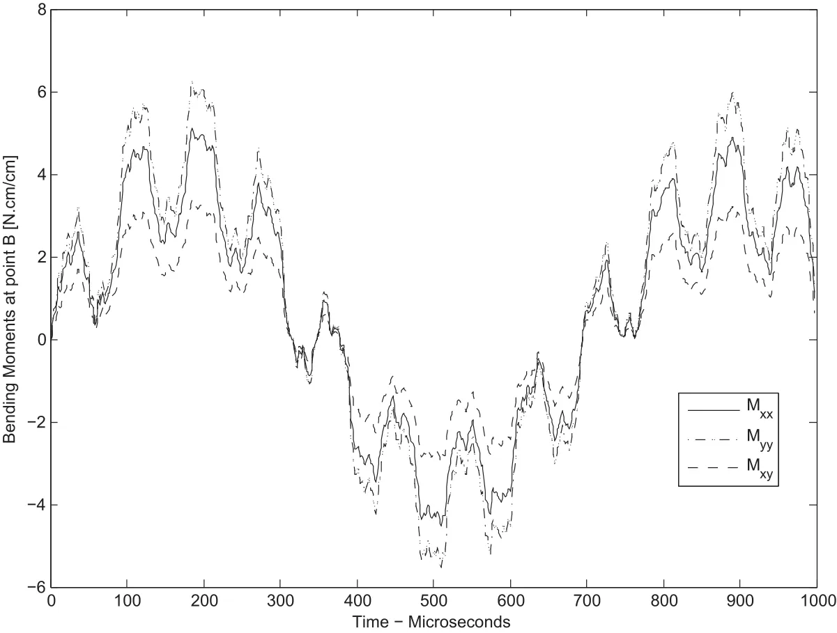
Figure 19:Bending resultant stress at point B for circular plate with hole
BEM model with 149 internal points and 32 elements as presented in figure 17 is used in this analysis.Figure 16 shows deflections at points C,D,E and F for the time-interval considered.This figure shows pole points at 320 and 740 microseconds approximately,where no deflection is experimented by the plate.Figures 18 and 19 shows bending moments at points A and B.These figures show high period bending moments(about 740 ms.),medium-range period variations(100 ms.approximately)and high-frequency variations of bending moments(less than 1 m-s.).This high-frequency variations is highly related with wave stress propagation.However,more research work must be done because numerical noise influence could be present.
7 Conclusions
A direct time-domain Boundary Element Method formulation for transient analysis of symmetric laminated thick plates was presented.Formulation is based on the elastostatic fundamental solution of the governing equations of the problem and takes into account rotatory inertia of the plate.The Radial Integration Method is used to treat domain integrals related with inertial mass and distributed surface loads.In order to validate the proposed formulation,numerical examples was presented and results compared with FEM solutions.Very good agreement between BEM and FEM solutions were obtained,thus demonstrating the reliability of the proposed formulation.Future investigations should focus on harmonic and transient analysis laminated composite thick plates taking into account damping effects.
Acknowledgement:This work was supported by Department of Mechanical Engineering at Universidad Tecnológica of Bolívar.
A.Sahli,S.Boufeldja,S.K.;Rahmani,O.(2014):Failure analysis of anisotropic plates by the boundary element method.In:Journal of Mechanics,vol.30,pp.561-570.
Bathes,K.J.(2007):Finite Element Procedures.Prentice-Hall.
Beskos,D.E.(2003):Dynamic analysis of structures and structural systems.In:Boundary Element Advances in Solid Mechanics,vol.440,pp.1-53.
Dirgantara,T.;Aliabadi,M.(1999):A new boundary element formulation for shear deformable shells analysis.International Journal for Numerical Methods In Engineering,vol.45,pp.1257-1275.
Duddeck,F.M.(2010):Fourier BEM:Generalization of boundary element methods by fourier transform.Springer.
E.L.Albuquerque,P.S.;de Paiva,W.P.(2007):The radial integration method applied to dynamic problems of anisotropic plates.In:Communications in Numerical Methods in Engineering,vol.23,pp.805-818.
E.L.Albuquerque,P.Sollero,W.V.;Aliabadi,M.H.(2006):Boundaryelement analysis of anisotropic kirchhoff plates.In:International Journal of Solids and Structures,vol.43,pp.4029-4046.
Fata,S.N.(2012):Treatment of domain integrals in boundary element methods.In:Applied Numerical Mathematic,vol.62,pp.720-735.
Gao,X.(2002):The radial integration method for evaluation of domain integrals with boundary only discretization.In:Eng.Analysis with Boundary Elements,vol.26,pp.905-916.
Gaul,L.;Kogl,M.;Wagner,M.(2003):Boundary Element Methods for Engineers and Scientists:An Introductory Course with Advanced Topics.Springer.Katsikadelis,J.T.(2014):The Boundary Element Method for Plate Analysis.Elsevier.
Manolis,G.D.;Beskos,D.E.(1998):Boundary Element Methods in Elastodynamics.Unwin Hyman Editors.
Mukherjee,S.(2013):The Boundary Element Method.In:International Journal of Computational Methods,vol.10,pp.1-90.
Partridge,P.W.;Brebbia,C.A.;Wrobel,L.C.(1992):The Dual Reciprocity Boundary Element Method.Computational Mechanics Publications.
Perez-Gavilán,J.;Aliabadi,M.(2001):A symmetric Galerkin boundary element method for dynamic frequency domain viscoelastic problems.In:Computers and Structures,vol.79,pp.2621-2633.
Providakis,C.P.;Beskos,D.E.(1999):Dynamic analysis of plates by boundary elements.In:Appl Mech Rev,vol.52,pp.213-236.
Rashed,Y.F.(2000):Topics in Engineering Vol 35:Boundary Element Formulations for Thick Plates.WIT Press.
Reddy,J.N.(2004):Mechanics of Laminated Composite Plates and Shells:Theory and Analysis.CRC Press.
Reddy,J.N.;Roman,A.;Arciniegas,A.;F.,M.(2010):Finite Element Analysis for Composite Structures in:Encyclopedia of Aerospace Engineering.John Wiley and Sons.
Sapountzakis,E.J.(2010):Recent Developments in Boundary Element Methods.WIT Press.
Tenek,L.T.;Argyris,J.(2010):Finite Element Analysis for Composite Structures.Springer.
Useche,J.(2014):Boundary element analysis of shear deformable shallow shells under harmonic excitation.Computater Modelling in Engineering and Science Journal,vol.100,pp.105-118.
Useche,J.;Albuquerque,E.(2012): Dynamic analysis of shear deformable plates using the dual reciprocity method.Engineering Analysis with Boundary Element Journal,vol.36,pp.627-632.
Useche,J.;Albuquerque,E.;Sollero,P.(2012): Harmonic analysis of shear deformable orthotropic cracked plates using the Boundary Element Method.Engineering Analysis with Boundary Elements Journal,vol.36,pp.1528-1535.
Vasiliev,V.;Morozov,E.(2001):Recent Developments in Boundary Element Methods.Elsevier.
W.Portilho de Paiva,P.S.;Albuquerque,E.L.(2011): Modal analysis of anisotropic plates using the boundary element method.In:Engineering Analysis with Boundary Elements,vol.35,pp.1248-1255.
Wang,J.(1991):Boundary element method for orthotropic thick plates.In:Acta Mechanica Sinica,vol.7,pp.258-266.
Wen,P.;Adetoro,M.;Xu,Y.(2008):The fundamental solution of Mindlin plates with damping in the Laplace domain and its applications.Engineering Analysis with Boundary Elements Journal,vol.32,pp.840-882.
Wen,P.;Aliabadi,M.(2000):Application of dual reciprocity method to plates and shells.Engineering Analysis with Boundary Elements Journal,vol.24,pp.583-590.
Wen,P.;Aliabadi,M.(2006): Boundary element frequency domain formulation for dynamic analysis of Mindlin plates.International Journal for Numerical Methods in Engineering,vol.67,pp.1617-1640.
Wen,P.;Aliabadi,M.;Young,A.(2000):Plane stress and plate bending coupling in BEM analysis of shallow shells.International Journal for Numerical Methods in Engineering,vol.48,pp.1107-1125.
Wen,P.;Aliabadi,M.;Young,A.(2000): The boundary element method for dynamic plate bending problems.International Journal of Solid and Structures,vol.37,pp.5177-5188.
Wrobel,L.C.;Aliabadi,M.H.(2002):The Boundary Element Method Volume 2:Applications in Solid and Structures.Wiley.
Zhang,J.;Atluri,S.(1986):A boundary/interior element method for quasi-static and transient response analyses of shallow shells.Computer and Structures,vol.24,pp.213-233.
1Universidad Tecnológica de Bolívar,Cartagena,Colombia

