Large Eddy Simulation Combined with Characteristic-Based Operator-Splitting Finite Element Method
Da-guo WangBin HuQing-xiang Shui
Large Eddy Simulation Combined with Characteristic-Based Operator-Splitting Finite Element Method
Da-guo Wang1,2,Bin Hu1,Qing-xiang Shui1
A numerical large eddy simulation(LES)method combined with the characteristic-based operator-splitting finite element method is proposed.The subgrid eddy viscosity model is used to calculate sub-grid stress in LES.In each time step,the governing equations are split into diffusive and convective parts.The convective part is first discretized by using the characteristic Galerkin method and then solved explicitly.The backward-facing step flow and the flow past a single cylinder are adopted to validate the model.Results agree with existing numerical results or experimental data.The flow past two cylinders in tandem arrangement is also studied atRe=1000.The critical spacing is obtained in the range of 2.25Dto 2.5Dthrough the change characteristics of the streamlines and hydrodynamic forces as spacing.We further analyze the hydrodynamic forces at the critical spacing range.
large eddy simulation;characteristic-based operator-splitting finite element method;backward-facing step flow; flow past a single cylinder; flow past two cylinders in tandem arrangement.
1 Introduction
Numerical simulations are crucial in the study and control of turbulence,which is a common phenomenon in fluid motion.Three numerical simulation methods are mainly used to simulate turbulence,namely,direct numerical simulation(DNS)[Piller,Nobile,and Hanratty(2002)],Reynolds averaged Navier-Stokes(RANS)[Shur,Spalart,Strelets,and Andrey(2008)],and large eddy simulation(LES)[Breuer(1998a)].LES has been widely used to study some complex flows,such as turbulent mixing and aerodynamic noise,because of its lower computational cost and higher accuracy than DNS and RANS[Mahesh,Constantinescu,and Moin(2004);Moin and Mahesh(1998)].LES involves the division of turbulent fluctuation into large-scale and small-scale motions by applying a low-pass filter,direct computation of the resolved large-scale motions,and modeling of the in fluence of the filtered small-scale motions on the resolved large scales[Mahesh,Constantinescu,and Moin(2004)].
The finite element method(FEM)has been widely used to solve various fluid dynamic problems;it is a powerful tool particularly for solving problems with complex geometry or boundary conditions.However,the conventional Galerkin FEM is known to have the potential to lead to distortion and oscillation of numerical solutions with increasing Reynolds number because the convective term becomes dominant and exhibits strong nonlinear characteristics.To overcome this drawback,various stabilized FEMs,such as streamline upwind/Petrov-Galerkin(SUPG)formulations[Brooks and Hughes(1982);Tezduyar and Ganjoo(1986)],Taylor-Galerkin(T-G)method[Selmin,Donea,and Quartapelle(1985)],Galerkin least square techniques[Franca and Frey(1992)],characteristic Galerkin method[Zienkiewicz and Codina(1995);Zienkiewicz,Morgan,Satya Sai,Codina,and Vasquez(1995);Bao,Zhou,and Huang(2010);Ding and Wu(2012)],and finite increment calculus method[Oñate,Valls,and García(2007)],have been developed.[Heinrich,Huyakorn,Zienkiewicz,and Mitchell(1977)] first suggested the Petrov-Galerkin type of weighting function to introduce an upwind effect in finite element discretization.[Brooks and Hughes(1982)]proposed the well-known SUPG scheme,in which the upwind effects occur only in the direction of the velocity resultant.A convective operator can also be stabilized with a high-order temporal approximation called the T-G method[Selmin,Donea,and Quartapelle(1985)].The introduction of the characteristic Galerkin method presents great impetus for the development of numerical procedures for the solutions of convection-dominated problems.[Zienkiewica and Codina(1995)]further developed the characteristic Galerkin method and combined it with a split scheme of the fractional step method to produce the well-known characteristic-based split(CBS)algorithm,which is widely used in computational fluid dynamics.
[Atluri and Zhu(1998)]developed the Meshless Local Petrov Galerkin(MLPG)method.The numerical results in[Lin and Atluri(2000);Lin and Atluri(2001)]indicate that the MLPG method is promising to solve the convection dominated fluid mechanics problems.[Avila and Atluri(2009)]coupled the MLPG method with a fully implicit pressure correction approach.[Han,Rajendran and Atluri(2005)]developed the Meshless Local Petrov-Galerkin(MLPG) finite-volume mixed method for the large deformation analysis of static and dynamic problems.Another mixed approaches,the Meshless Local Petrov-Galerkin(MLPG)Mixed collocation method developed to solve the Cauchy inverse problems of Steady-State heat transfer in[Zhang,He,Dong,Li,Alotaibi,and Atluri(2014)].
The popular numerical solution strategies for unsteady Navier-Stokes(N-S)equations are based on operator splitting[Langtangen,Mardal,and Winther(2002)].NS equations are split into a series of simple and familiar equations,such as advection equations,diffusion equations,advection-diffusion equations,Poisson equations,and explicit/implicit updates.Ef ficient numerical methods are easier to construct directly for these standard equations than for N-S equations.[Wang,Wang,Xiong,and Tham(2011);Wang,Tham,and Shui(2013)]solved the unsteady incompressible N-S equations with the characteristic-based operator-splitting(CBOS)FEM,which combines the operator-splitting and CBS algorithms.In this method,the simple explicit characteristic temporal discretization,which involves a local Taylor expansion,is referenced from the CBS algorithm and applied to the discretization of the convective part.
A numerical method that combines LES and CBOS FEM is developed in this study.The backward-facing step flow and the flow past a single cylinder are adopted to validate the model.The flow past two cylinders in tandem arrangement is studied atRe=1000.The rest of this paper is organized as follows:Section 2 introduces 2D unsteady incompressible LES-governing equations.Section 3 explains the numerical method and finite element solutions.Section 4 describes the solution process.Section 5 and Section 6 present the validation of the present model with the backward-facing step flow and the flow past a single cylinder.Section 7 elucidates the study of the flow past two cylinders in tandem arrangement.Section 8 concludes this paper.
2 LES-governing equations
2D unsteady viscous incompressible flows can be governed by N-S equations.Their dimensionless forms are expressed as

wherei,j=1,2,(u1,u2)=(u,v),uis the horizontal velocity,vis the vertical velocity,pis pressure,tis time,(x1,x2)=(x,y),xis the horizontal coordinate,andyis the vertical coordinate.is the Reynolds number,withUas the characteristic velocity,las the characteristic length,andυas the kinematic viscosity.
The spatial filtering of the 2D unsteady viscous incompressible N-S equations with box filter produces the following equations[Sagaut(2000)]:

3 Numerical method and finite element solutions
3.1 Operator-splitting algorithm
By adopting the operator-splitting algorithm,we split LES-governing equations in Eqs.(8)and(9)into the diffusive part

3.2 Characteristic method of the convective term
The convective part(11)is a hyperbolic equation with the following characteristic equation:
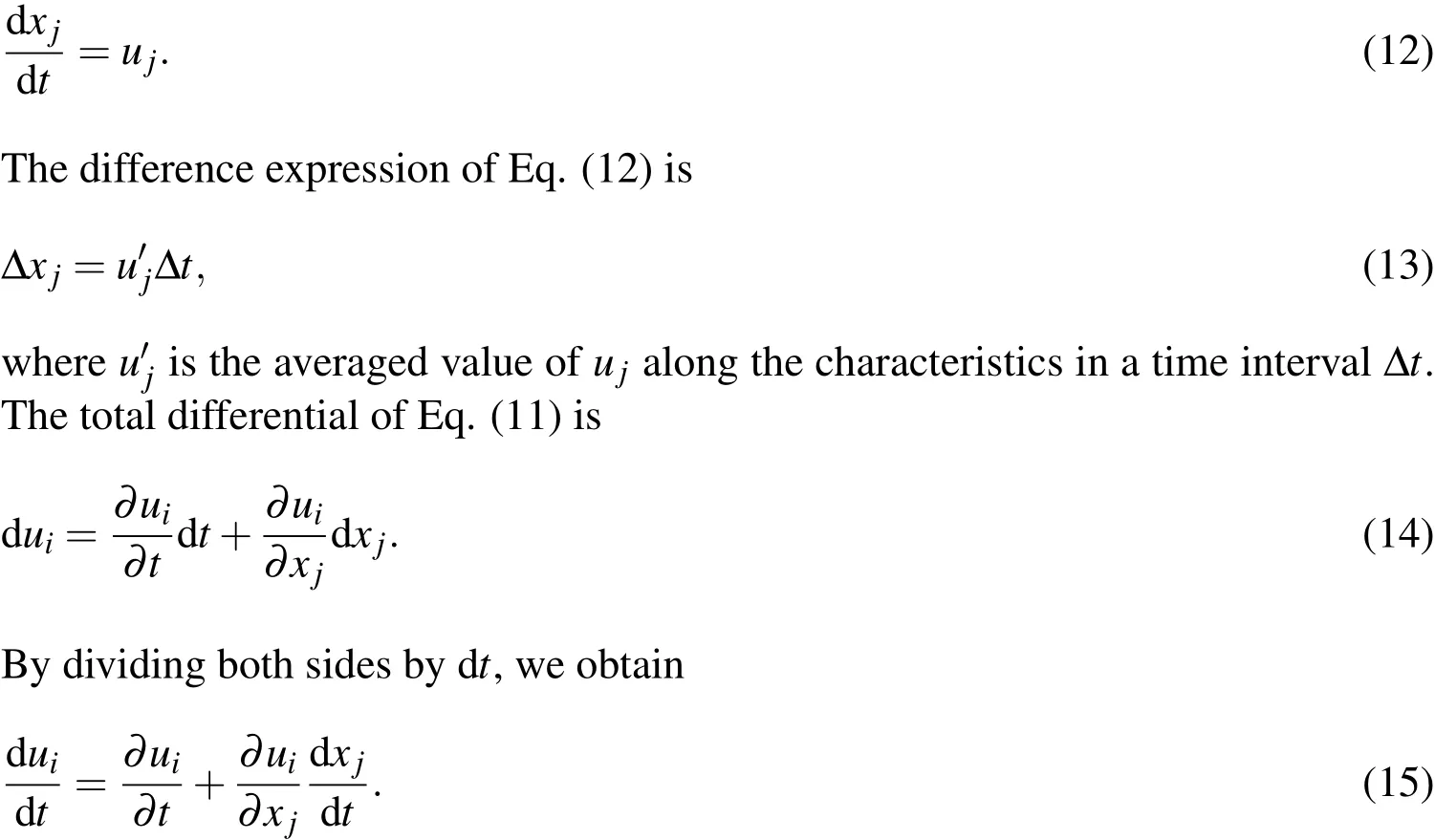
By substituting Eq.(12)into Eq.(15),we obtain
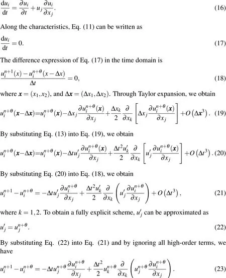
The last term in Eq.(23)is the steady diffusive term along the streamline that is directly derived from the convective part.The present method differs from the previous method,in which the weight function is modi fied by an artificial or empirical factor.Thus,the difficulty in choosing the weight function in the SUPG method or other FEMs is avoided.
3.3 Finite element solutions
After the sub-grid eddy viscosity coefficientυtin Eq.(9)is linearized,Eq.(9)becomes identical to Eq.(2).Hence,the finite element solutions for the diffusive part(10)and convection display expression(23)can be referred to the method by[Wang,Wang,Xiong,and Tham(2011)].
4 Solution process
1)Eq.(6)is solved to obtainυt.
2)The diffusive part(10)is solved to obtainandpn+1.
4)For the next time step,step 1 is repeated.
5 Backward-facing step flow
The backward-facing step flow is widely used to validate turbulence models[Le,Moin,and Kim(1997);Wang,Fan,and He(2003);Wang,Zhang,Yu,Wang,Guo,and Lin(2003)].In this section,we compare the horizontal velocity with existing data and analyze the flow patterns by simulating the backward-facing step flow.
5.1 Physical model
Fig.1 presents the problem layout.In the figure,His the step height,his the inlet height,L1is the step length,andL2is the length of the flow field behind the step.A no-slip boundary condition is imposed on the solid walls,and the pressure on the outlet boundary is taken as zero.

Figure 1:Backward-facing step flow con figuration.
5.2 Comparison of velocity
Fig.2 shows the horizontal velocity distributions along the vertical sections at different positions atRe=1000.In this section,the in flow velocity is 6×y×(1-y),the average of which is the characteristic velocity;his the characteristic length,andh=1;H=0.9423h;L1=4h;L2=36h.In the figure,the dot markers denote the numerical results of[Guerrero and Cotta(1996)],and the solid lines denote the present results.The present results agree well with the numerical results of[Guerrero and Cotta(1996)].
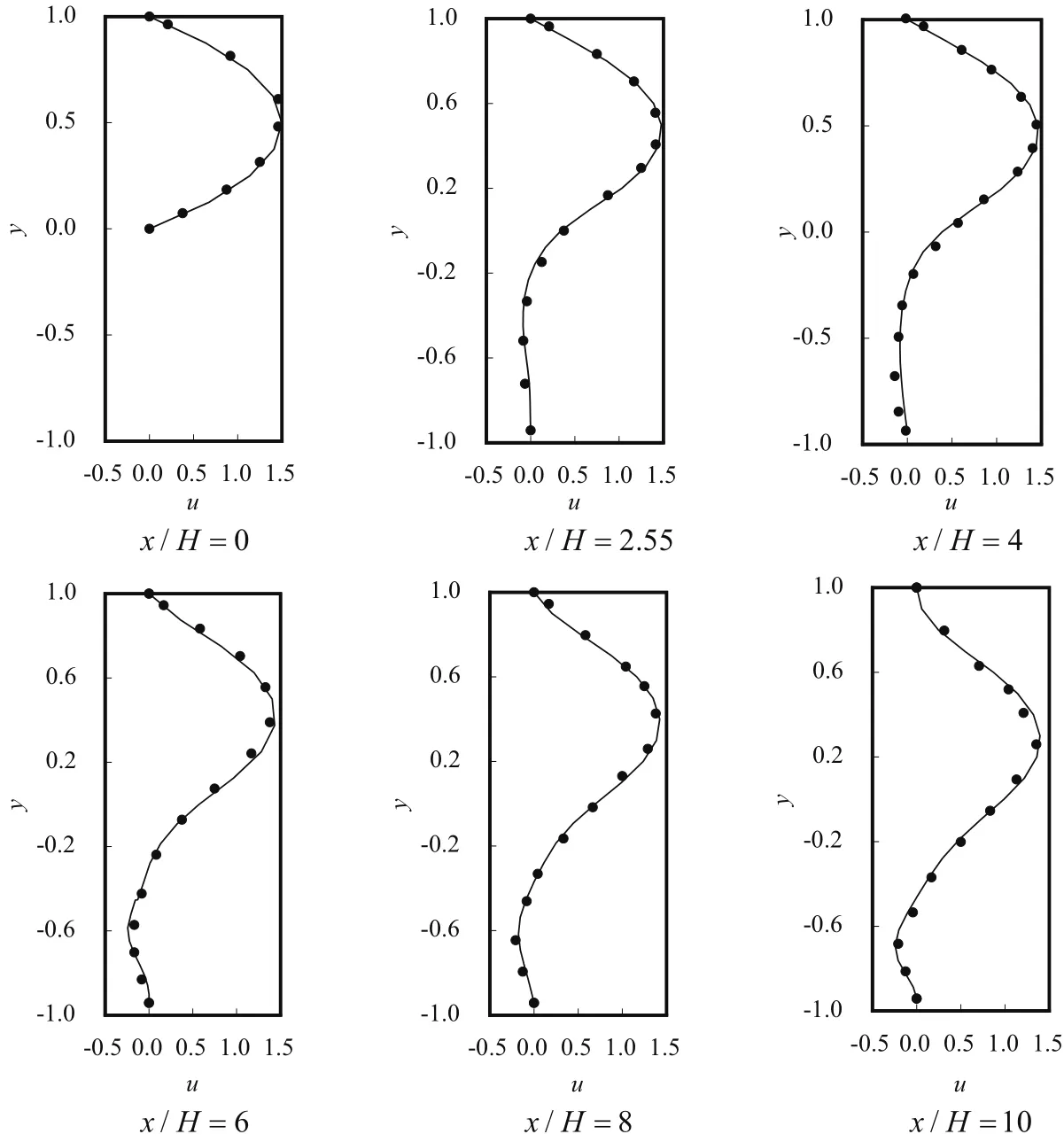
Figure 2:Velocity pro files at Re=1000.
Fig.3 shows the horizontal velocity distributions along the vertical sections at different positions atRe=3025.In this section,the in flow velocity is obtained from the experimental data by[Denham,Briard,and Patrick(1975)];the maximum in flow velocity is the characteristic velocity;His the characteristic length,andH=1;h=2H;L1=4H;L2=36H.In the figure,the dot markers denote the experimental results of[Denham,Briard,and Patrick(1975)],and the solid lines denote the present results.The present results agree well with the experimental data of[Denham,Briard,and Patrick(1975)],although inconsiderable errors exist possibly because of the 3D effect of the turbulence.
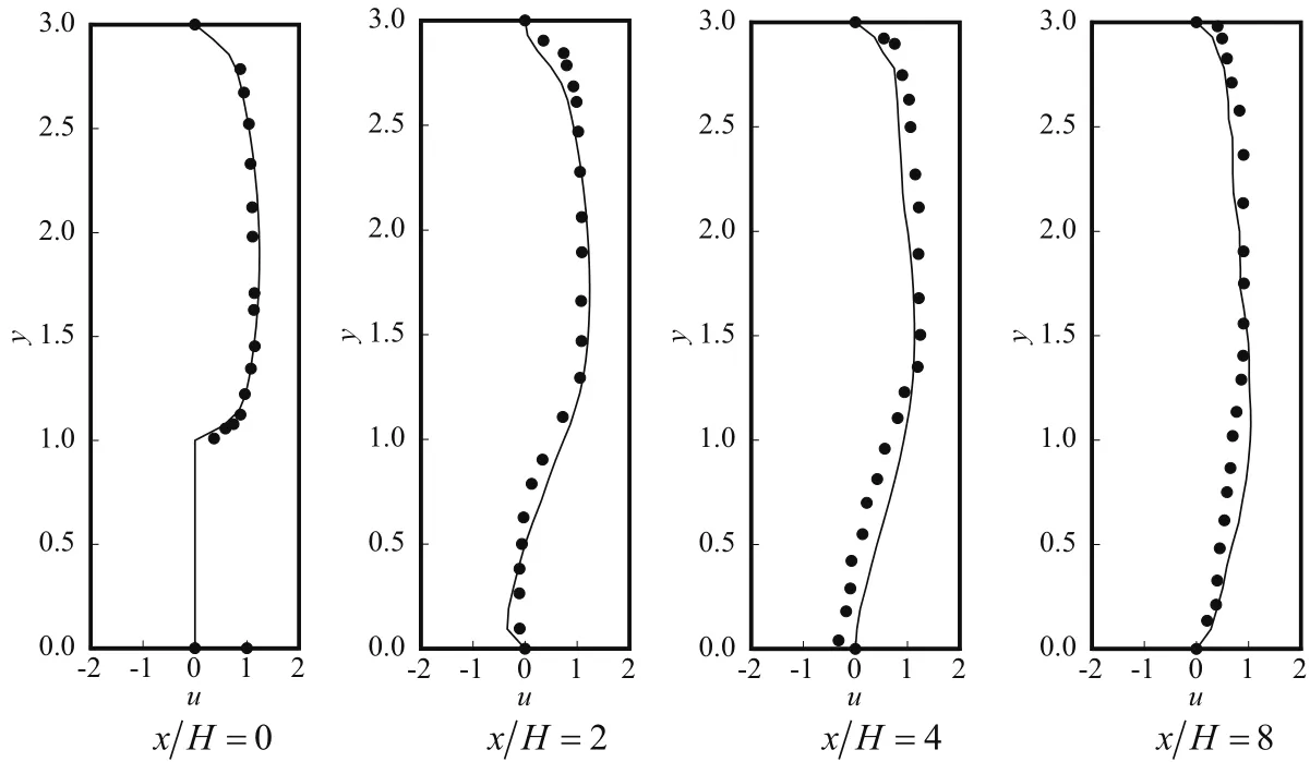
Figure 3:Velocity pro files at Re=3025.
5.3 Flow patterns at Re=3025
Fig.4 shows the streamlines of the backward-facing step flow in approximately one cycle period at Re=3025.The inlet flow separates at the sharp corner because of the sudden expansion of the flow channel,and the top vortex is produced at the top right of the step,as shown in Fig.4(a).Figs.4(b)to 4(d)show that the top vortex expands and gradually squeezes the bottom vortex until the bottom vortex disappears.The top vortex then impinges onto the lower wall,and the next bottom vortex is produced,as shown in Figs.4(e)and 4(f).
6 Flow past a single cylinder
The flow past a single cylinder is also widely investigated both experimentally and numerically.The flow past a single cylinder is simulated atRe=200,1000,3900 to validate the present model.
6.1 Physical model
The domain consists of a cylinder placed at a distance of 5Dfrom the inlet,whereDis the diameter of the cylinder.The distance from the cylinder center to the top and bottom sides is equal to 8D.The exit of the domain is placed at a distance of 16Dfrom the cylinder center.The Dirichlet boundary conditions,namely,u=1 and v=0,are enforced at the in flow boundary.The no-slip condition is applied to the cylinder surface,whereas the free-slip condition is applied to the two sidewalls.At the outlet boundary,the convective boundary condition is specified for both velocity component∂ui/∂t+∂ui/∂x=0.A rectangular flow field of 21D×16D is divided into 3,022,3,238,and 6,071 nine-node finite elements that correspond to Re=200,1000,3900;the total numbers of nodal points are 12,340,13,788,and 24,638,respectively.Fig.5 shows the sketch of the computation grid at Re=3900.
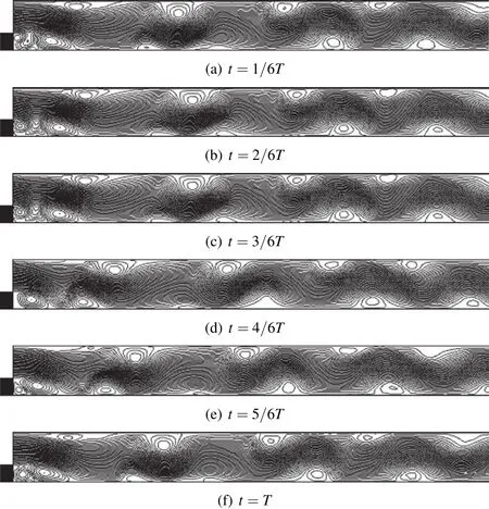
Figure 4:Streamlines at different times at Re=3025.
6.2 Flow parameters
Tab.1 shows the mean drag coefficientlift coefficient amplitudeand Strouhal number(St).They are evaluated as follows:

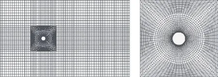
Figure 5:Sketch of computation grid at Re=3900.

whereθis the azimuth angle measured from the rear point on the horizontal axis of the cylinder and in the clockwise direction,andf0is the dimensional vortex shedding frequency.The first term in the right of Eqs.(24)and(25)represents the contribution of the pressure,and the second term corresponds to the part from the viscous force.
Tab.1 indicates that the present results are well within the range of the results reported by other researchers.Fig.6 shows the time-dependent behavior of the drag(Cd)and lift(Cl)coefficients with time atRe=200,1000,3900.The period of the drag coefficient is approximately twice that of the lift coefficient for the three Reynolds numbers.

Table 1:Comparison of flow parameters for flow field at Re=200,1000,3900.
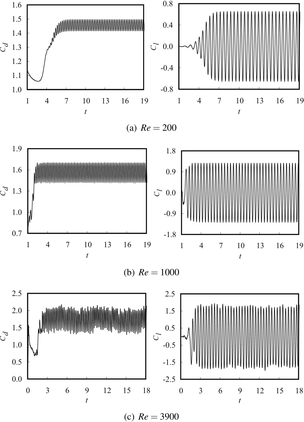
Figure 6:Time variation of drag and lift coefficients at different Reynolds numbers.
6.3 Flow field structure
Fig.7 shows the pressure and streamline during half a cycle of vortex shedding at Re=200,1000,3900.The von Kármán vortex streets develop in the wake of the three Reynolds numbers.As the Reynolds number increases,the centers of the vortices in the near wake gradually approach the horizontal line through the geometric center of the cylinder.
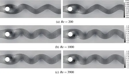
Figure 7:Instantaneous pressure and streamline during half a cycle of vortex shedding at different Reynolds numbers.
6.4 Lift coefficient and the corresponding development of flow field in a cycle at Re=3900
Fig.8 shows the lift coefficient and the corresponding development of pressure and streamline in approximately one cycle of vortex shedding atRe=3900.The dot markers in Fig.8(a)correspond to the time instants of flow field in Figs.8(b)to 8(f).The subplots of Figs.8(b)to 8(f)correspond to the time instants of the maximum positive lift coefficient,zero lift coefficient,maximum negative lift coefficient,zero lift coefficient,and maximum positive lift coefficient,respectively.Figs.8(b)and 8(f)illustrate that the lower side of the cylinder experiences a high pressure in the vortex shedding cycle,whereas the upper side of the cylinder is subjected to a low pressure and comprises a large well-developed attached vortex.Hence,the maximum positive lift force on the cylinder is observed[shown at points b and f in Fig.8(a)].Analogously,the maximum negative lift force can be determined from Fig.8(d),and the zero lift force can be determined from Figs.8(c)and 8(e).The development of pressure in Figs.8(b)to 8(f)indicates that the distribution of pressure on the upwind surface of the cylinder has insignificant change and symmetry in one cycle of vortex shedding.Therefore,the pressure on the upwind surface inconsiderably affects the formation of the lift force.The streamline in Fig.8 shows the von Kármán vortex street.
7 Flow past two cylinders in tandem arrangement at Re=1000
The flow past two cylinders in tandem arrangement exhibits a remarkably complex behavior that is of interest for many engineering applications,such as offshore platforms,cooling towers,heat exchanger tubes,and marine risers.For the flow past two cylinders in tandem arrangement atRe=1000,[Mittal,Kumar,and Raghuvanshi(1997)]employed a stabilized element formulation to study the change characteristic of the vorticity,streamfunction fields,and the lift or drag coefficients of the upstream and downstream cylinders at spacings of 2.5Dand 5.5D,but the critical spacing was not obtained.[Jester and Kallinderis(2003)]researched the vorticity characteristic at spacings of 2Dto 2.5Dby a second-order SUPG projection scheme,and they obtained a critical spacing of approximately 2.38Dthrough numerical simulation and experiment.Detailed research of the flow past two cylinders in tandem arrangement atRe=1000 is presented in this section.
7.1 Physical model
Fig.9 shows the computational domain of the flow past two cylinders in tandem arrangement.The domain consists of an upstream cylinder placed at a distance of 5Dfrom the inlet.The exit of the domain is placed at a distance of 16Dfrom the center of the downstream cylinder.The distance from the center of the cylinders to the top and bottom sides is equal to 8D.Ldenotes the distance between the two cylinder centers.The boundary conditions are consistent with those of the flow past a single cylinder.L=2D,2.25D,2.5D,4D,5.5Dare computed.Fig.10 shows the sketch of the computation grid atL=2D.
7.2 Critical spacing
7.2.1Flow patterns at different spacings
Fig.11 shows the streamlines at different spacings.In the figure,differences exist in the flow patterns at different spacings,especially whenL≤2.25DandL≥2.5D.A recirculation region can be found in the gap between the two cylinders whenL≤2.25D,whereas vortex shedding occurs in the gap whenL≥2.5D.Therefore,the critical spacing exists in the flow past two cylinders in tandem arrangement atRe=1000.
7.2.2Hydrodynamic forces at different spacings
Fig.12shows the variations in the drag and lift coefficients as spacing.In the figure,◦and·denote the results of[Jester and Kallinderis(2003)],where◦denotes the results of the upstream cylinder,and·denotes the results of the downstream one;△and▲denote the results of[Mittal,Kumar,and Raghuvanshi(1997)],where

Figure 8:Lift coefficient and the corresponding development of pressure and streamline in a cycle at Re=3900.
△denotes the results of the upstream cylinder,and▲denotes the results of the downstream one;the lines denote the results of the present model,where the solid lines denote the results of the upstream cylinder,the dashed lines denote the results of the downstream one,and the dash dot lines denote the results of a single cylinder.Fig.12(a)shows that the mean drag of the upstream cylinder increases whenL/D=2.25 to 2.5 and is close to the results of a singer cylinder;the mean drag of the downstream cylinder is negative whenL/D≤2.25,but it suddenly increases to a positive value whenL/D=2.5.Fig.12(b)shows that the lift amplitudes of the two cylinders experience a sharp increment whenL/D=2.25 to 2.5.Subsequently,the lift coefficient amplitudes of the upstream cylinder approach the results of the singer cylinder,whereas the lift coefficient amplitudes of the downstream one are stable and greater than the results of a singer cylinder.
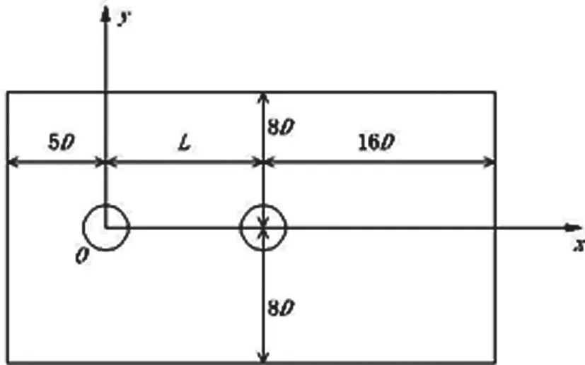
Figure 9:Computational domain of flow past two cylinders in tandem arrangement.

Figure 10:Fluid domain mesh model when L=2D.
Thus,the critical spacing of the flow past two cylinders in tandem arrangement atRe=1000 is in the range of 2.25Dto 2.5D,which agrees with the result of[Jester and Kallinderis(2003)].
7.3 Comparative analysis of hydrodynamic forces at the critical spacing range
7.3.1Analysis of hydrodynamic force at L=2.25D
Fig.13 shows the pressure at four different moments during a cycle whenL=2.25D.A relatively stable low-pressure region forms in the gap between the two cylinders,which results in a negative drag force on the downstream cylinder.The reduction in the upstream cylinder drag force is due to the presence of the downstream cylinder that leads to pressure increase behind the upstream cylinder in comparison with the flow past a single cylinder,as shown in Fig.7(b).The upstream cylinder undergoes a rather small lift amplitude because of the lack of vortex shedding.As the vorticity contours in Fig.14,vortex formation occurs a few diameters away from the downstream cylinder,which results in less severe oscillation in lift.Hence,the lift amplitude on the downstream cylinder is smaller,but it is still larger than the upstream one because of the dominance of the wake interference effect for this small spacing.
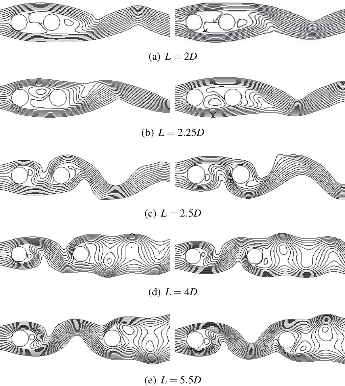
Figure 11:Streamline chart at different spacings.
7.3.2Analysis of hydrodynamic force at L=2.5D
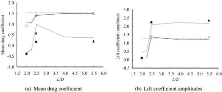
Figure 12:Variations in lift and drag coefficients as spacing.
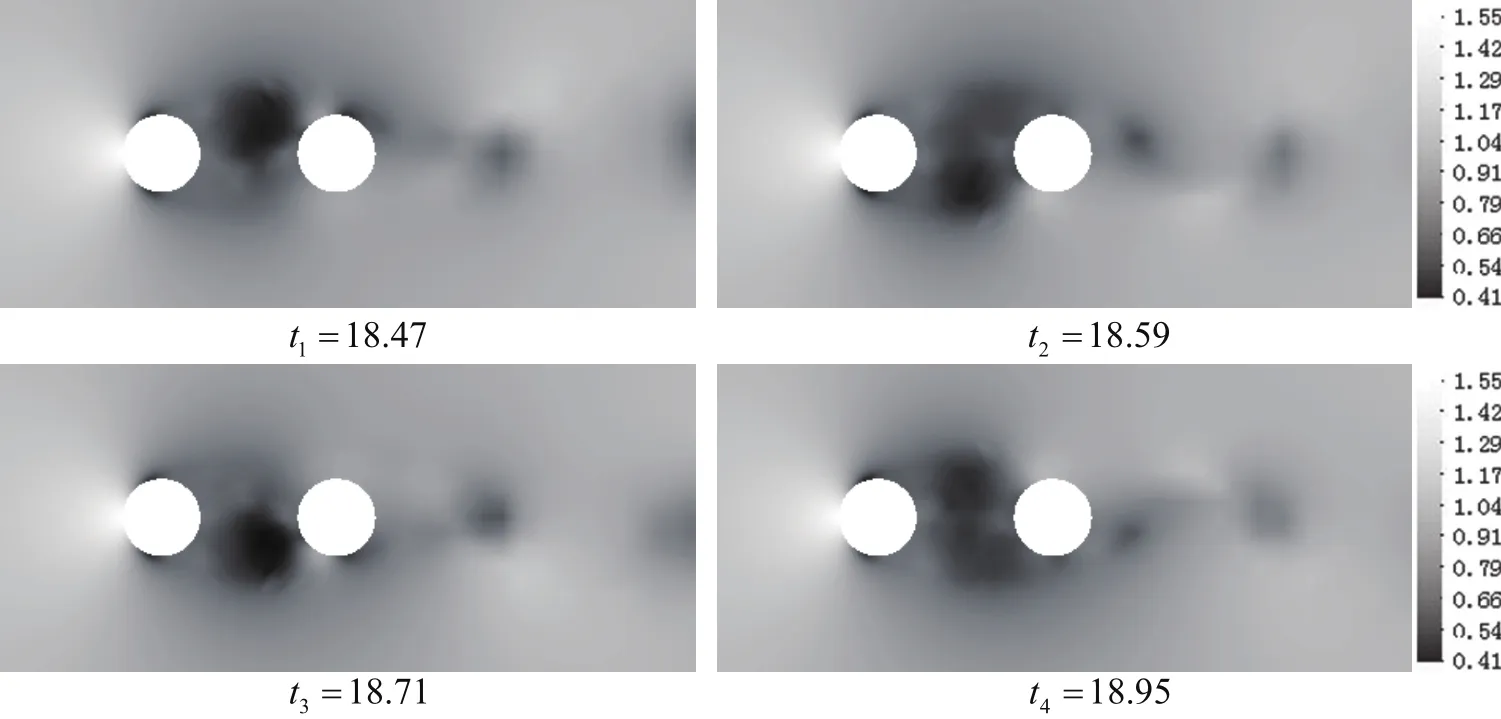
Figure 13:Instantaneous pressure during a cycle when L=2.25D.
Fig.15 shows the pressure at six different moments during a cycle whenL=2.5D.Unlike the pressure in the gap whenL=2.25Din Fig.13,a negative pressure region is formed alternately on the top and bottom sides of the upstream cylinder wake region,while the gap spacing increases toL=2.5D.Consequently,vortex shedding occurs in the wake region of the upstream cylinder,and the variations in the hydrodynamic forces of the two cylinders follow an oscillating trend with large amplitudes with respect to the case ofL=2.25D.The drag force and lift amplitude on the upstream cylinder are close to the results of the single cylinder.Compared with that in the wake region,the pressure on the upwind surface of the downstream cylinder becomes significantly higher,but it is still lower than the pressure on the upwind surface of the upstream one.As a result,the drag force on the downstream cylinder increases to a positive value,but it is still smaller than the results of the single cylinder.In Figs.15(a)to 15(c),the positive pressure on the upper side of the downstream cylinder upwind surface increases,whereas the negative pressure on the lower side of the downstream cylinder upwind surface decreases.Thus,a sharp increment in the lift amplitude on the downstream cylinder occurs.
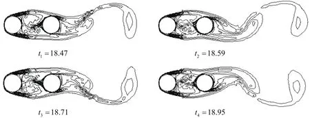
Figure 14:Instantaneous vorticity contours during a cycle when L=2.25D.
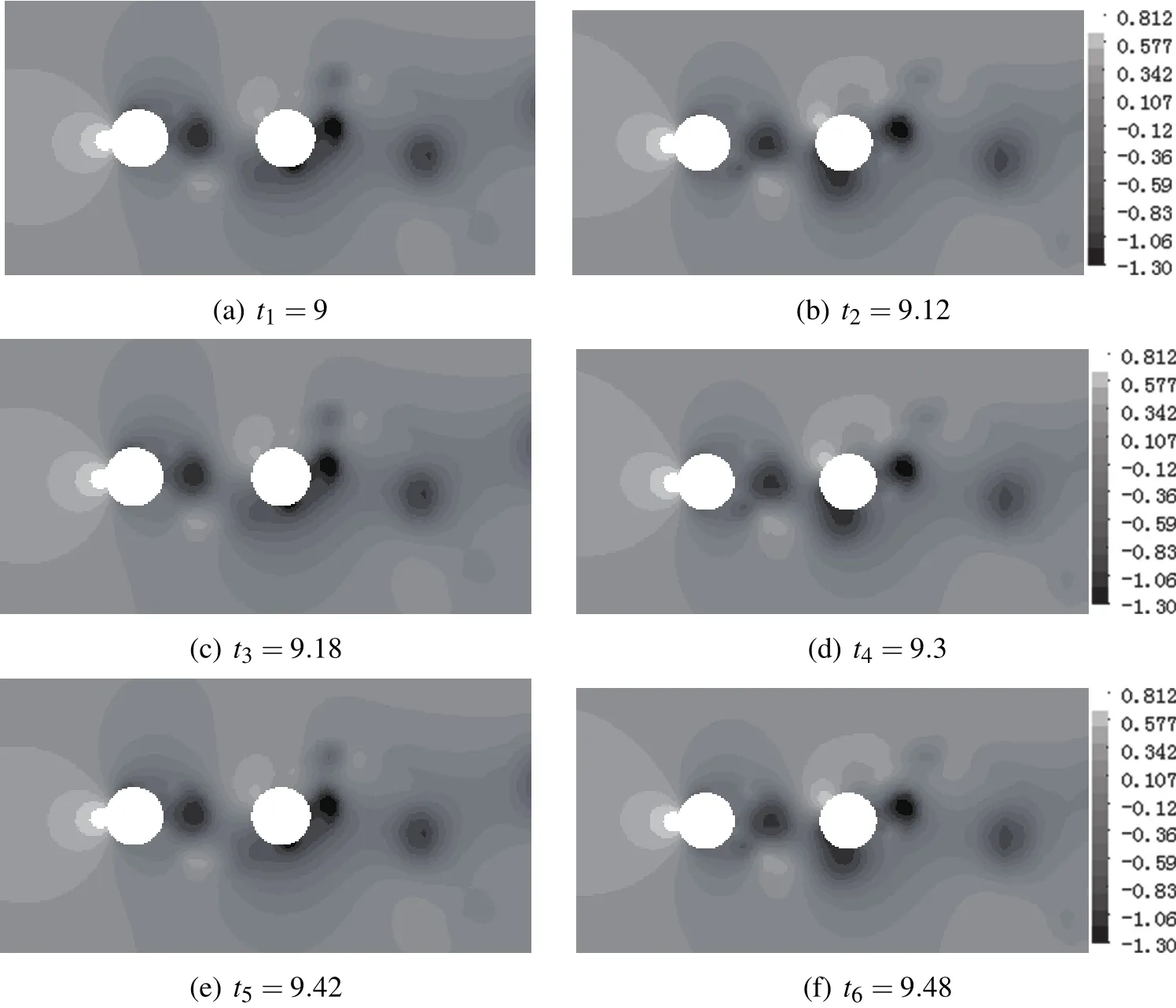
Figure 15:Instantaneous pressure during a cycle when L=2.5D.
8 Conclusions
We propose a numerical method that combines LES with CBOS FEM.The backward facing step flow and the flow past a single cylinder are adopted to verify the present model.Results are well within the range of existing numerical results and experimental data,and the present model is reliable.With the Reynolds number increasing,the centers of the vortices in the near wake gradually approach the horizontal line through the geometric center of the cylinder.The flow past two cylinders in tandem arrangement atRe=1000is also studied.The critical spacing is obtained in the range of 2.25Dto 2.5Dthrough the change characteristic of the streamlines and hydrodynamic forces as spacing.The reasons for the hydrodynamic force change at the critical spacing range are analyzed.
i.AtL=2.25D,a relatively stable low-pressure region forms in the gap between the two cylinders,which results in a negative drag force on the downstream cylinder.The reduction in the upstream cylinder drag force is due to the presence of the downstream cylinder that leads to pressure increase behind the upstream cylinder.The upstream cylinder undergoes a rather small lift amplitude because of the lack of vortex shedding.Vortex formation occurs a few diameters away from the downstream cylinder,which results in less severe oscillation in lift.Hence,the lift amplitude on the downstream cylinder is smaller,but it is still larger than the upstream one because of the dominance of the wake interference effect for this small spacing.
ii.AtL=2.5D,a negative pressure region is formed alternately on the top and bottom sides of the upstream cylinder wake region.Consequently,vortex shedding occurs in the wake region of the upstream cylinder,and the variations in the hydrodynamic forces of the two cylinders follow an oscillating trend with large amplitudes with respect to the case ofL=2.25D.The drag force and lift amplitude of the upstream cylinder are close to the results of the single cylinder.Compared with that in the wake region,the pressure on the upwind surface of the downstream cylinder becomes significantly higher,but it is still lower than the pressure on the upwind surface of the upstream one.As a result,the drag force on the downstream cylinder increases to a positive value,but it is still smaller than the results of the single cylinder.The positive pressure on the upper side of the downstream cylinder upwind surface increases,whereas the negative pressure on the lower side of the downstream cylinder windward surface decreases.A sharp increment in the lift amplitude on the downstream cylinder thus occurs.
The present model is feasible and efficient for backward-facing step flow, flow past a single cylinder,and flow past two cylinders in tandem arrangement.The model also provides a prospective research method for solving 3D LES at a high Reynolds number.
Acknowledgement:The authors would like to acknowledge the financial support by the National Natural Science Foundation of P.R.China(Grant Nos.41372301,51349011),the Preeminent Youth Talent Project of the Southwest University of Science and Technology(Grant No.13zx9109),and the Postgraduate Innovation Fund Project by the Southwest University of Science and Technology(Grant No.14ycxjj0039).
Atluri,S.N.;Zhu,T.(1998):A new Meshless Local Petrov-Galerkin(MLPG)approach in computational mechanics.Computational Mechanics,vol.22,no.2,pp.117-127.
Avila,R.;Atluri,S.N.(2009):Numerical solution of non-steady flows,around surfaces in spatially and temporally arbitrary motions,by using the MLPG method.Computer Modeling in Engineering&Ences,vol.54,no.1,pp.15-64.
Bao,Y.;Zhou,D.;Huang,C.(2010):Numerical simulation of flow over three circular cylinders in equilateral arrangements at low Reynolds number by a secondorder characteristic-based split finite element method.Computers&Fluids,vol.39,no.5,pp.882-899.
Breuer,M.(1998a):Large eddy simulation of the subcritical flow past a circular cylinder:numerical and modeling aspects.International Journal for Numerical Methods in Fluids,vol.28,no.9,pp.1281-1302.
Breuer,M.(1998b):Numerical and modeling in fluences on large eddy simulations for the flow past a circular cylinder.International Journal of Heat and Fluid Flow,vol.19,no.98,pp.512-521.
Brooks,A.N.;Hughes,T.J.R.(1982): Streamline upwind/Petrov-Galerkin formulations for convection dominated flows with particular emphasis on the incompressible Navier-Stokes equations.Computer Methods in Applied Mechanics and Engineering,vol.32,no.1-3,pp.199-259.
Chen,T.Q.;Zhang,Q.H.;Cheng,L.(2010):Performance investigation of 2D lattice Boltzmann simulation of forces on a circular cylinder.Transaction of Tianjin University,vol.16,no.6,pp.417-423.
Deardorff,J.W.(1970):Convective velocity and temperature scales for the unstable planetary boundary layer and for Rayleigh convection.Journal of the Atmospheric Sciences,vol.27,no.8,pp.1211-1213.
Denham,M.K.;Briard,P.;Patrick,M.A.(1975):A directionally-sensitive laser anemometer for velocity measurements in highly turbulent flows.Journal of Physics E:Scientific Instruments,vol.8,no.8,pp.681-683.
Ding,D.Y.;Wu,S.Q.(2012): Direct numerical simulation of turbulent flow over backward-facing at high Reynolds numerical.Science China Technological Science,vol.11,no.11,pp.3213-3222.
Franca,L.P.;Frey,S.L.(1992): Stabilized finite element methods:II.The incompressible Navier-Stokes equations.Computer Methods in Applied Mechanics and Engineering,vol.99,no.9,pp.209-233.
Guerrero,J.S.P.;Cotta,R.M.(1996):Benchmark integral transform results for flow over a backward-facing step.Computers&Fluids,vol.25,no.5,pp.527-540.
Han,Z.D.;Rajendran,A.M.;Atluri,S.N.(2005): Meshless local petrovgalerkin(MLPG)approaches for solving nonlinear problems with large deformations and rotations.Computer Modeling in Engineering and Sciences,vol.10,no.1,pp.1-12.
Harichandan,A.B.;Roy,A.(2010):Numerical investigation of low Reynolds number flow past two and three circular cylinders using unstructured grid CFR scheme.International Journal of Heat and Fluid Flow,vol.31,no.2,pp.154-171.
Heinrich,J.C.;Huyakorn,P.S.;Zienkiewicz,O.C.;Mitchell,A.R.(1977):An ‘upwind’ finite element scheme for two-dimensional convective transport equation.International Journal for Numerical Methods in Engineering,vol.11,no.1,pp.131-143.
Hu,C.;Koterayama,W.(1994):Numerical study on a two-dimensional circular cylinder with a rigid and an elastic splitter plate in uniform flow.International Journal of Offshore and Polar Engineers,vol.4,no.3,pp.193-199.
Jester,W.;Kallinderis,Y.(2003):Numerical study of incompressible flow about fixed cylinder pairs.Journal of Fluids and Structures,vol.17,no.4,pp.561-577.
Kravchenko,A.G.;Moin,P.(2000):Numerical studies of flow over a circular cylinder at ReD=3900.Physics of Fluids,vol.12,no.2,pp.403-417.
Langtangen,H.P.;Mardal,K.A.;Winther,R.(2002):Numerical methods for incompressible viscous flow.Advances in Water Resources,vol.25,no.8,pp.1125-1146.
Le,H.;Moin,P.;Kim.J.(1997):Direct numerical simulation of turbulent flow over a backward-facing step.Journal of Fluid Mechanics,vol.330,no.1,pp.349-374.
Lin,H.;Atluri,S.N.(2000):Meshless Local Petrov Galerkin(MLPG)method for convection-diffusion problems.Computer Modeling in Engineering and Sciences,vol.1,no.2,pp.45-60.
Lin,H.;Atluri,S.N.(2001): The Meshless Local Petrov-Galerkin(MLPG)method for solving incompressible Navier-Stokes equations.Computer Modeling in Engineering and Sciences,vol.2,no.2,pp.117-142.
Liu,C.;Zheng,X.;Sung,C.H.(1998):Preconditioned multigrid methods for unsteady incompressible flows.Journal of Computational Physics,vol.139,no.1,pp.35-57.
Mahesh,K.;Constantinescu,G.;Moin,P.(2004): A numerical method for large-eddy simulation in complex geometries.Journal of Computational Physics,vol.197,no.1,pp.215-240.
Moin,P.;Mahesh,K.(1998):Direct numerical simulation:a tool in turbulence research.Annual Review of Fluid Mechanics,vol.30,no.5,pp.539-578.
Mittal,S.;Kumar,V.;Raghuvanshi,A.(1997):Unsteady incompressible flows past two cylinders in tandem and staggered arrangements.International Journal for Numerical Methods in Fluids,vol.25,no.11,pp.1315-1344.
Oñate,E.;Valls,A.;García,J.(2007):Modeling incompressible flows at low and high Reynolds numbers via a finite calculus- finite element approach.Journal of Computational Physics,vol.224,no.1,pp.332-351.
Piller,M.;Nobile,E.;Hanratty,T.J.(2002):DNS study of turbulent transport at low Prandtl numbers in a channel flow.Journal of Fluid Mechanics,vol.458,no.1,pp.419-441.
Sagaut,P.(2000): Large eddy simulation for incompressible flows.Springer-Verlag,Heidelberg.
Selmin,V.;Donea,J.;Quartapelle,L.(1985):Finite element methods for nonlinear advection.Computer Methods in Applied Mechanics and Engineering,vol.52,no.1-3,pp.817-845.
Smagorinsky,J.(1963): General circulation experiments with the primitive equations:I.The basic experiment.Monthly Weather Review,vol.91,no.3,pp.99-164.
Shur,M.L.;Spalart,P.R.;Strelets,M.K.;Andrey,K.T.(2008):A hybrid RANS-LES approach with delayed-DES and wall-modelled LES capabilities.International Journal of Heat and Fluid Flow,vol.29,no.6,pp.1638-1649.
Tezduyar,T.E.;Ganjoo,D.K.(1986): Petrov-Galerkin formulations with weighting functions dependent upon spatial and temporal discretization:Applications to transient convection-diffusion problems.Computer Methods in Applied Mechanics and Engineering,vol.59,no.1,pp.49-71.
Wang,D.G.;Wang,H.J.;Xiong,J.H.;Tham,L.G.(2011):Characteristicbased operator-splitting finite element method for navier-stokes equations.Science China Technological Science,vol.54,no.8,pp.2157-2166.
Wang,D.G.,Tham L.G.,Shui Q.X.(2013): Dam-break model with characteristic-based operator-splitting finite element method.Computer Modeling in Engineering and Sciences,vol.91,no.5,pp.355-376.
Wang,B.;Zhang,H.Q.;Yu,J.F.;Wang,X.L.;Guo,Y.C.;Lin,W.Y.(2003): Numerical simulation of large eddy simulation structures evolution behind backward-facing step(in Chinese).Chinese Quartery Meshanics,vol.24,no.2,pp.166-173.
Wang,X.H.;Fan,H.M.;He,Z.Y.(2003):Numerical simulation of backward facing step(in Chinese).Chinese Journal of computational Mechanics,vol.20,no.3,pp.361-365.
Xu,S.;Wang,Z.J.(2006):An immersed interface method for simulating the interaction of a fluid with moving boundaries.Journal of Computational Physics,vol.216,no.2,pp.454-493.
Zhang,T.;He,Y.Q.;Dong,L.T.;Li,S.;Alotaibi,A.;Atluri,S.N.(2014):Meshless local petrov-galerkin mixed collocation method for solving cauchy inverse problems of steady-state heat transfer.Computer Modeling in Engineering and Sciences,vol.97,no.6,pp.509-533.
Zienkiewicz,O.C.;Codina,R.A.(1995):A general algorithm for compressible andincompressible flow-PartI.thesplit,characteristic-basedscheme.International Journal for Numerical Methods in Fluids,vol.20,no.8-9,pp.869-885.
Zienkiewicz,O.C.;Morgan,K.;Satya Sai,B.V.K.;Codina,R.;Vasquez,M.(1995): A general algorithm for compressible and incompressible flow-Part II.Tests on the Explicit form.International Journal for Numerical Methods in Fluids,vol.20,no.8-9,pp.887-913.
1School of Environmental and Resources,Southwest University of Science and Technology,Mianyang,621010,China
2Corresponding author.Email address:dan_wangguo@163.com

