The Fundamentals Underlying the Computations of Acceleration for General Dynamic Applications:Issues and Noteworthy Perspectives
M.Shimada,A.Hoitinkand K.K.Tamma,2
The Fundamentals Underlying the Computations of Acceleration for General Dynamic Applications:Issues and Noteworthy Perspectives
M.Shimada1,A.Hoitink1and K.K.Tamma1,2
To-date,with the exception of the Newmark method and the midpoint rule,most computational algorithms under the umbrella of LMS methods,which are predominantly employed in research and commercial software fail to properly evaluate acceleration computations accurately for conducting the numerical dynamic simulations.Indeed,this is not trivial and a sound theoretical basis of the fundamental underlying issues is described in detail.In this paper,we provide a resolution and point-out several noteworthy perspectives to address the proper evaluation of acceleration computations for structural dynamics applications with focus on the class of LMS methods as an illustration.
1 Introduction
The present paper describes the accurate and precise evaluation of acceleration computations which play an important role in general structural dynamics applications.Computational algorithms for time dependent problems are mostly designed after the semi-discretization is done on the partial differential equations governing the equations of motion.In particular,these computational algorithms are predominantly the class of linear multi-step(LMS)methods that are widely used for general engineering applications and most commercial software.Numerous research efforts have been undertaken in designing computational algorithms over the past fi fty years or so starting with the Houbolt method,Newmark based methods and the like.The two principal classes of algorithms are numerically non-dissipative methods such as Newmark,the velocity based scheme,the classical midpoint rule,and controllable numerical dissipative methods to control high frequency behavior encountered in stiff dynamical systems.It is well known that numerous application areas exist in science and engineering wherein acceleration calculations need to be precise.Typical applications encompass determination of g-forces encountered in dynamical systems to include impact applications where it is extremely useful to have a knowledge of the accelerations imparted at critical sections of vehicle structures carrying sensitive electronics,in the evaluation of base accelerations imparted due to missiles/torpedos and the like in the vicinity of ship structures which is critical for assessments of ship dynamics,earthquake engineering applications involving base ground motion,and the like.The fundamental question that is posed regarding all these developments to-date is:"are the accelerations that are being computed accurate and proper"?Alternatively,this paper presents the exsiting drawbacks and provides a fundamental resolution to the accurate and proper computation of accelerations for both numerically non-dissipative and dissipative methods with a clear resolution for the entire class of LMS methods.Consequently,future developments can now accurately implement the proper dynamics for general engineering applications precisely.For illustration,the focus of this paper is on the class of LMS methods which are most popular in research and commercial software.
Recently,Zhou and Tamma Tamma,Zhou,and Sha(2000);Tamma,Kanapady,Zhou,and Sha(2000);Zhou and Tamma(2004b,a,2006)described a unified theory underlying computational algorithms for designing computational algorithms for time dependent phenomenon.In particular,focusing attention on the class of LMS methods for general structural dynamics applications which are the predominant methods in most commercial software,Zhou and Tamma described a general framework under the umbrella of generalized single step single solve[GSSSS]family of algorithms.This novel framework encompasses most of the LMS methods that have been developed over the past fifty years or so,and also additionally includes new and optimal methods that have not been available to-date that are optimal for various applications in structural dynamics.A brief highlight of the so-called big picture follows next so as to put into context the subtle issues and the underlying resolution of the existing drawbacks and deficiencies prevalent in acceleration computations to-date.The GSSSS family of algorithms can be viewed as the fully discretized time integration algorithms for the equation of motion which contains most past and also new and recent computational developments.The novelty of this framework is that a single precise time integration module is all that is needed to be implemented which provides all possible algorithms as available choices and options for the analyst to use.Basically,within this framework there exist two distinct families of algorithms termed as constrained U(displacement-overshoot aspects)and constrained V(velocity overshoot aspects)family of algorithms.They simply characterize the overshoot behavior on the displacement or the velocity fields of a particular algorithm.For example,the Newmark Newmark(1959)algorithm which is a numerically non-dissipative method belongs to the U0 family with particular additional characteristics termed as V0;that is it does not have any overshoot behavior for the displacement or velocity.Alternately,the so-called HHT-αHilber,Hughes,and Taylor(1977),is a numerically controllable dissipative method that was introduced to control high frequency behavior and it is a U0V1 algorithm belonging to the U0 family(same as Newmark),which is characterized by no overshoot in displacement but inherits first order overshoot in the velocity field.These overshoot characteristics play an important role in that they enter the computations;consequently,higher overshoot behavior may cause nonlinear iterations in implicit dynamics calculations to not converge.There exist numerous algorithms that are contained within the GSSSS family including other more recently developed optimal algorithms with and without controllable numerical dissipation that are preferable for many engineering applications Zhou and Tamma(2004b).
The GSSSS Family of Algorithms:Let the time interval of interest,T=tL−t0,be divided intontsub-intervals such that···<t¯n≡tL.The time step size is defined as Δt:=tn+1−tn.Suppose the initial conditions(q,˙q)(t0)=(q0,v0)1are given;then,we can compute the numerical displacement(configuration)qn+1,velocity vn+1,and acceleration an+1forn∈{0,1,2,···,−1}from:
wheretn+W1:=(1−W1)tn+W1tn+1,and the algorithmic configuration,velocity,and acceleration vectors are given by

And the corresponding updates are designed to be

The algorithmic scalar parameters are given by
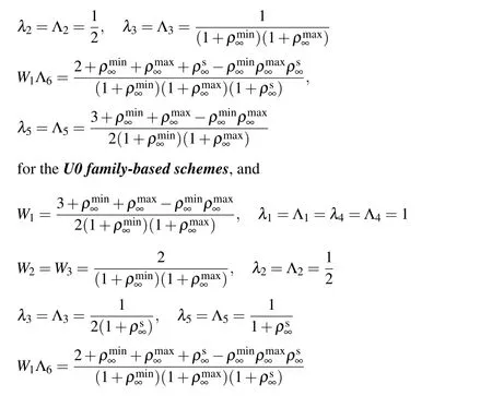
for the V0 family-based schemes.The additional algorithmic parameters ηi(fori=1,2,3)govern the various features of the corresponding explicit members within this general algorithmic framework for second-order systems.For the implicit case(ηi=1 fori=1,2,3),the roots must satisfy the following relation:

For linear dynamical systems,the right-hand side of Eq.(1)may yield

where C and K denote the damping and stiffness matrices,respectively;and f(t)denotes the time-dependent external load vector.
The Issue:While the displacement and velocity vectors are indeed evaluated precisely at the time levelt=tn+1,the acceleration computations that are reported in the literature and the like,are,in general,not accurately determined and/or are being misinterpreted by the research and commercial computational community at large.For example while it is true(actually happens to be true)for the implicit Newmark method that an+1indeed is accurately computed at time leveln+1,for most of the other methods this is not the general case.As a demonstration,Fig.1 shows convergence plots using the traditional(misinterpreted)method for the single degree of freedom problem described later in the numerical examples.We see that for the implicit Newmark method and the classical midpoint rule(numerically non-dissipative methods)that the order of convergence for all three variables is indeed two.For these two special cases,it is indeed true that the accelerations resulting from the algorithm falls at the timen+1.However,for the particular numerically non-dissipative velocity based scheme Tamma and Namburu(1990)in the sense of LMS methods,this is not true(the acceleration comes out to be first order only).For all other algorithms,including the numerically non-dissipative velocity based scheme shown,the acceleration time level resulting from the algorithm is"shifted"from displacement and velocity time levels,and thus incorrectly yields only first order accurate results.
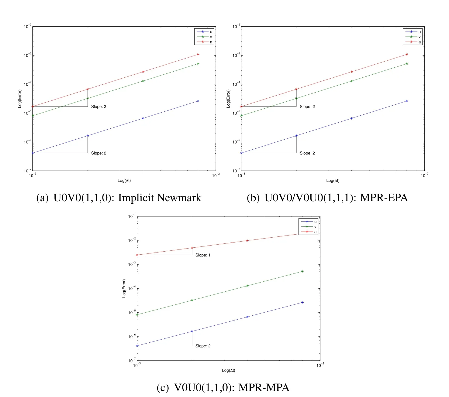
Figure 1:Traditional convergence of algorithms without dissipation(Notice that the acceleration is incorrectly shown to come out to be first-order for the MPRMPA algorithm)
It is also routinely shown in the literature that for algorithms which include controllable numerical dissipation,the order of accuracy in the acceleration is less than two.Fig.2 illustrates just one example of this using for example,the U0V1 optimal scheme,which is identical to the so-called three parameter optimal method or its equivalent,namely,the generalized-α method(and is taken from Ref.Erlicher,Bonaventura,and Bursi(2002)).
There exists a fundamental misconception in the use and interpretation of the term"acceleration and the time level at which it is interpreted and computed;"and this paper provides a deep insight and a resolution to the issue,within the entire LMS class of algorithms chosen simply for illustration of the basic ideas.Understanding the time level at which the acceleration is computed in general,for the class of computational algorithms in the sense of the LMS methods is the key to showing proper accuracy.Again,the fundamental concept is that,in the general case of computational algorithms,the acceleration is strictlynotbeing calculated at time leveltn+1.How and where the acceleration time level is calculated and how to describe an accurate convergence plot which shows correct accuracy is discussed at length below based for the framework of generalized single step single solve(GSSSS)algorithms developed by Zhou and Tamma Zhou and Tamma(2004b)for the entire class of LMS methods that are predominant in most research and commercial software.
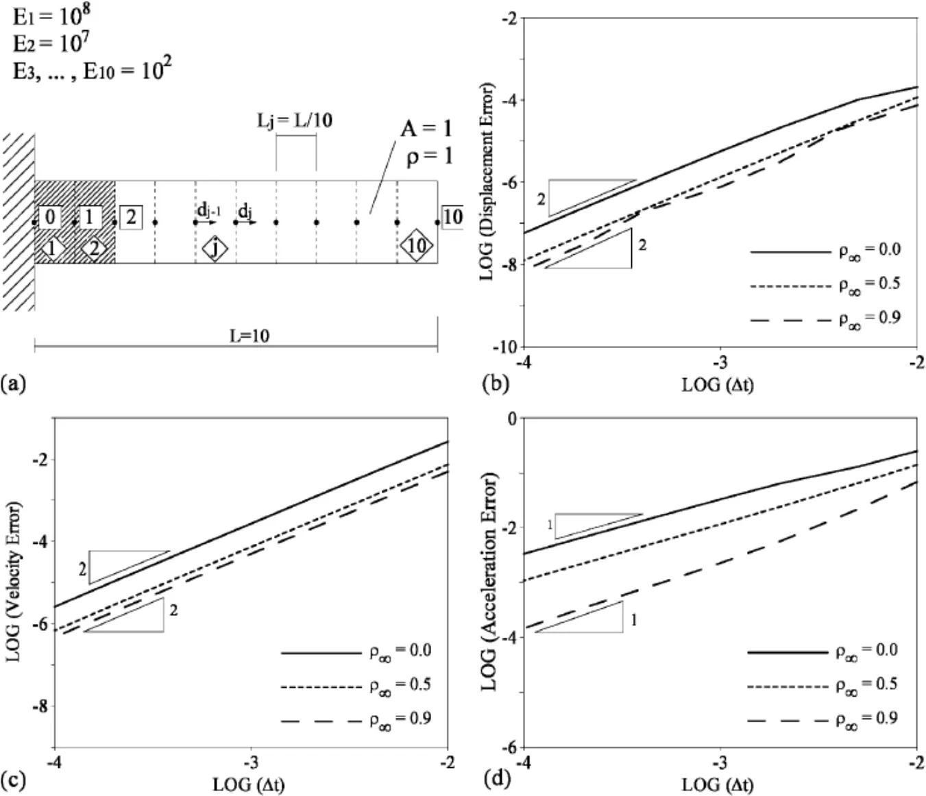
Figure 2:Figures from Ref Erlicher,Bonaventura,and Bursi(2002)showing the displacement and velocity second order time accurate,but the acceleration is only cited to be first order time accurate using the U0V1 optimal scheme, which is identical to the three parameter optinal method or its equivalent,namely,the generalized α method
2 Time Level Analysis of the GSSSS Family of Algorithms
Both the U0 and V0 based-family of algorithms shown above have been particularly designed to be of second-order time accuracy in the displacement,velocity,and external load vectors;however,we get only first-order accuracy in the acceleration vector if we assume an≈(tn)and an+1≈(tn+1).In order to guarantee the second-order time accuracy in all the variables,one must be aware of the correct time level of approximations for q,˙q,and¨q as

Theorem 1(Time Level of Acceleration)
In the U0 and V0 based-family of algorithms,the second-order time accuracy in¨q,i.e.,

is obtained for a solution satisfying

Proof.In this proof,we only consider the V0 family-based algorithms since the proof for the U0 family-based algorithms is more straightforward,and we get the same result as stated in the theorem above.The V0 family-based algorithms can be cast into

where the algorithmicand f are given by

Using Equation(10),we get

wherep=2 andp=1 fors≥2 ands=1,respectively,in an−(tn−φ)=O(Δts).Similarly,

and

Since the Taylor series expansions about timet=tnyields

we get


H e n c e,an+1−s≥ 2 f o r φ =W1(Λ6−1).
Remark 2.1(Theorem 1)
1.Choosing the initial value off(t0)],actually still yields the second-order accuracy in¨q.
2.It is important to note thatapproximations ofat time t=tnand t=tn+1,respectively.Therefore,to plot thetrue accelerationtime history,one must use

at the first time step and

for n∈ {1,2,···,nt−1}.This is illustrated in Fig.3.
3.The spectral conditionin the V0 family-based al-gorithms leads to

with
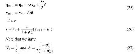
for V0:rule with the endpoint acceleration(MRP-EPA),which is the classical midpoint rule,and the newmidpoint rule with the midpoint acceleration(MRPMPA),respectively.Notice that the difference betweenMPR-EPA and MPRMPA is

Note that the information regarding the acceleration at the previous time step is not required to evaluate the current acceleration,and consequently,the new MPR-MPA provides a a more robust computational algorithm for general dynamics applications in contrast to the classical MPR-EPA.In contrast to the single field form shown above,by eliminating the acceleration,Eq.(24)-Eq.(26)can be readily reduced to the two-field form version of the classical symplectic midpoint rule which takes the form

where=f(tn+1/2)can be used for the algorithmic time-dependent external
force instead of˜f=(fn+f)/2sincef(tn+α)−fn+α=O(Δt2)forα ∈ [0,1].
4.In the derivation of the GSSSS family of algorithms,the conditions of the
second-order time accuracy were imposed following the algorithms by de
sign concept;see Zhou and Tamma(2004b).From the truncation error anal
ysis for Eqs.(1)-(5),the necessary and sufficient conditions of the second
order time accuracy for the displacement and velocity are given as:

andΛ1= Λ4for a homogeneous case(f=0),andΛ1= Λ4=1for a non-homogeneous case(f/=0).Notice that the above conditions(for the non-homogeneous case)are a priori for the U0 and V0 family-based algorithms.In addition to the conditions,Eq.(30),we must introduceφ :=W1(Λ6−1)to guarantee the second-order time accuracy not only of the displacement and velocity,but also of the acceleration.Note that we can never obtain the second order-time accuracy of the acceleration if we break the conditions,Eq.(30),and the orders of accuracy of the displacement and velocity are always dependent upon each other in this algorithmic framework.However,the second order-time accuracy of the acceleration is not the necessary condition for the second order-time accuracy of the displacement and velocity.
Theorem 2(Time Level Consistency)
In order to guarantee the second-order time accuracy in all time-dependent vari-
ables,such asq(t),andf(t),in the discrete equation of motion,theymust be evaluated at the same time level t=t∗=tn+W1as

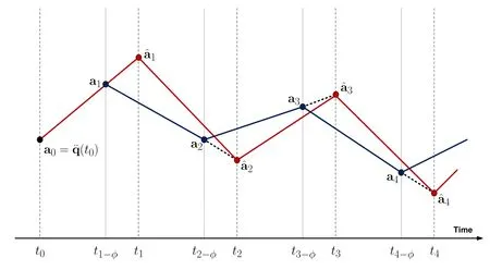
Figure 3:Illustration of the true acceleration history(red line).
Proof.By using the Taylor series expansions about timet=tn,we get


Therefore,the discrete equation of motion is evaluated at the time levelt=tn+W1where the second-order time accuracy in,and f are guaranteed.The time levelt∗=tn+W1is called the algorithmic time level.If the algorithmic balance equation is satisfied at the time levelt∗=tn+W1with the error(Δt2),the acceleration,velocity,and configuration are of second-order time accuracy. The algorithmic time level consistency at timet=tn+W1in the balance equation is illustrated in Fig.4.
Remark 2.2(Theorem 2)
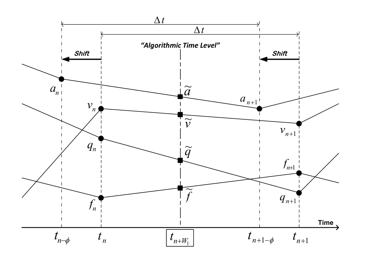
Figure 4:Illustration of the algorithmic time level
1.Extension to nonlinear systems:The time level consistency theorem plays a fundamental role when we extend and apply the GSSSS family of algorithms to nonlinear dynamical systems.The basic strategy is that we developtime integration schemes which satisfy the algorithmic time level consistency theorem at time level of tn+W1in order to guarantee the second order-time accuracy in all variables appear in discrete balance equations.See Shimada and Tamma(2012,2013);Har and Tamma(2012)for detailed discussions.
2.First order systems:The time level consistency theorem still holds for firstorder systems generally represented as=F(q,t)∀t∈Iwith given initial conditionq0=q(t0).That is,we discretize the balance equation with the algorithms by design concept such that the time level consistency at time t=tn+W1is guaranteed as follows:

wherein the above equationdenote the algorithmicqandvfor the first-order system.The time level ofvn must satisfyvn≈(tn−φ)for n∈{1,2,···}withφ=W1(Λ6−1).The resulting algorithm is known as the GSSSS-1(or GS4-1)family of algorithms;see Masuri,Sellier,Zhou,and Tamma(2011)for the detailed derivations and applications to linear transient first-order systems.
3 Implications of a Shifted Acceleration Time Level
U0 Family-based Algorithms:To gain a physical interpretation of acceleration time level shift denoted by φ ,note that φ needs to be viewed separately for each of the U0 and V0 families of algorithms due to the fact that values ofW1and Λ6are not the same.For the case of the family of U0 algorithms we have:

Therefore,φ :=W1(Λ6−1)can be written in terms of the roots as

Notice that φU0does not depend on.Recall that φ was defined to be the offset of acceleration from time leveltn.As such,the resulting values of acceleration for a given time step betweentnandtn+1are actually at timetn−φ+1.Fig.5a shows this time level vs.We see that for the family of U0 algorithms the calculated accelerations occur at a time betweentnandtn+1.In current practice it is being assumed by all researchers,that what all algorithms yield is the value of acceleration at timetn+1;this results in a maximum possible error in time of Δt,as demonstrated later.
V0 Family-based Algorithms:In a similar fashion to the U0 family of algorithms,a physical interpretation of φ can also be shown by considering the associated possible range of values.For the V0 family of algorithms we have:

Hence,we have:

Notice that φV0depends ononly.From Eq.42 we see that it is possible to describe and construct a plot of acceleration time level vs.(see Fig.5b).Notice that in the case of V0,the acceleration resulting from a single time step betweentnandtn+1is located betweenandtn+1resulting in a maximum possible error in time of,as demonstrated later.
Optimal Algorithms:From Eq.(39)or Eq.(42),we can obtain φ for the U0V0/V0U0optimal family of algorithms,i.e.,U0V0/V0U0(ρ∞,1,ρ∞)whereρ∞:=

Notice that φ for the V0U1 optimal family of algorithms,i.e.,algorithms given by setting ρ∞:=in the V0 family of algorithms,has the same φ as shown in Eq.(44).On the other hand,φ for the U0V1 optimal family of algorithms,i.e.,algorithms given by settingin the U0 family of algorithms,which is identical to the Generalized-α method,has the following φ:

These φ in terms of ρ∞∈ [0,1]are shown in Fig.5c.
To fully understand the impact of the above,consider the hypothetical situation of running a simulation to an end time of 0.5 sec(assumet0=0)with a time step size Δt=0.1 sec with a numerically dissipative algorithm U0V0(0,1,0)≡U0(0,1,0)which yields φ=0.5.The output of this hypothetical simulation would result in values of displacement,velocity,and acceleration at times seen in the following table.
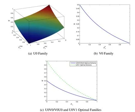
Figure 5:Time level of the resulting acceleration over time step tnto tn+1

n Time[sec]Displacement Velocity Acceleration True Acceleration 0 0.0 q0=q(0.0)v0=˙q(0.0)a0=¨q(0.00)ˆa0=¨q(0.0)1 0.1 q1≈q(0.1)v1≈˙q(0.1)a1≈¨q(0.05)ˆa1=2a1−a0≈¨q(0.1)2 0.2 q2≈q(0.2)v2≈˙q(0.2)a2≈¨q(0.15)ˆa2=1.5a2−0.5a1≈¨q(0.2)3 0.3 q3≈q(0.3)v3≈˙q(0.3)a3≈¨q(0.25)ˆa3=1.5a3−0.5a2≈¨q(0.3)4 0.4 q4≈q(0.4)v4≈˙q(0.4)a4≈¨q(0.35)ˆa4=1.5a4−0.5a3≈¨q(0.4)5 0.5 q5≈q(0.5)v5≈˙q(0.5)a5≈¨q(0.45)ˆa5=1.5a5−0.5a4≈¨q(0.5)
An outcome of this shift in the acceleration time level is that the notation implied(naively)in the selected algorithm leads to an interpretation that is somewhat misleading.The algorithm in the a-form solves for Δa=an+1−an≈¨q(tn+1−φ)−(tn−φ),and then uses the updates to obtain values of vn+1≈˙q(tn+1)and qn+1≈q(tn+1).As a result,what would be considered the output/results are actually values of qn+1and vn+1at timet=tn+1=t0+(n+1)Δtover the duration of the run-time and values of a at timet=tn+1−φ=t0+(n+1−φ)Δt,even though over the duration of the run-time the equation of motion was satisfied consistently at the same time level.As such,any algorithm that does not satisfy φ=0 produces data that is very easily misrepresented.The current understanding before the findings of this paper was that all time integration algorithms simply returned values of qn+1,vn+1,and an+1at timetn+1.This is strictly not not the case,in general.Therefore,the correct time history of qn+1,vn+1,and an+1should in fact appear with accelerations misaligned with displacements and velocities.To reiterate,if the goal of the hypothetical simulation described above was to obtain numerical values of q,,andat timet=0.5 sec,in general any of the algorithms which yield φ/=0 willnotprovide all three quantities correctly.This concept has extremely important implications about the manner in which numerically dissipative algorithms,as well as some non-dissipative methods,are used with respect to accelerations for the class of LMS methods.
4 Interpretation and Description of a Consistent Convergence Plot
Following the discussion and illustration of the algorithmic time level concept,we now are able to address the fact that in general,for numerically dissipative algorithms,to-date one is not able to demonstrate that the accelerations are second order time accurate but do obtain second order time accuracy for both displacements and velocities.For numerically non-dissipative algorithms such as the velocity based scheme,this also happens to be the case.To understand the resulting consequences of the shift in the time level which the algorithm returns on a convergence plot,we first must focus on how the plot is produced.
To construct a converge plot(notice here that convergence is always meant to mean convergence in time,not convergence of the spatial discretization),the same problem is run multiple times with only a change in the time step size.The time step is gradually reduced and the slope of the result yields the order of time accuracy of the variable.An end time of the simulation is chosen and the resulting displacement,velocity,and acceleration are compared to values of the exact solution at that time.If,as in most practical problems,there is no exact known analytic solution,then the simulation is run with a time step which is very small in comparison to the others and this run is considered to be the benchmark solution.The log of the error in the numerical solution is then plotted versus the log of the time step size used in the solution.The slope of the line generated by these points is then the convergence rate of the algorithm.
To visualize how the final step of the simulations used to generate the acceleration convergence plot looks like,Figs.6 are provided for illustration.The assumption is the simulation will be run using several different time step sizes,for example:
Δt1=Δt,Δt2=2Δt,Δt3=3Δt,and Δt4=4Δt.Without properly accounting for the acceleration offset,the results will show second order time accuracy for all three quantities only if φ=0,and otherwise will show second order time accuracy for the displacement and velocity,and only first order time accuracy in the acceleration as reported in the literature Erlicher,Bonaventura,and Bursi(2002).If the time step sizes are chosen as to properly align accelerations,then the comparison of the numerical solutions to the exact solution are occurring at the same time level.It is then,that these normally misrepresented accelerations can be readily proven to be second order time accurate.
To properly describe the convergence plot in which the value of acceleration from the numerical simulations are compared with the acceleration of the exact solution at precisely the same time,very close attention must be paid to the selection of the time step size for each simulation used in generating the plot.As an example,assume that the convergence plot will have 4 data points meaning that one has 4 numerical solutions which are being compared to an exact solution.Instead of defining 4 different time step sizes,let us define the total number of steps for each of the 4 solutions that we will use.Then calculate the corresponding time step size as follows:

It is shown below in the different numerical examples that using this procedure in fact results in properly obtaining second order accurate accelerations,thereby validating the assumption of the offset in the acceleration time level.The first example problem is a simple linear dynamic single degree of freedom problem for which we have an exact solution.The next example is a multi-DOF dynamic problem with nonlinear strain definition(Green strain).For illustration,a general purpose dynamic research code was developed to simulate any combination of springs and masses.Having tested the current assertions on codes ranging from single DOF to multi-DOF and both linear and non-linear dynamic problems,we have great confidence that the current work will advance the field of general numerically dissipative(and numerically non-dissipative as well)LMS class of algorithms.This will be of benefit in future ither developments and advances.
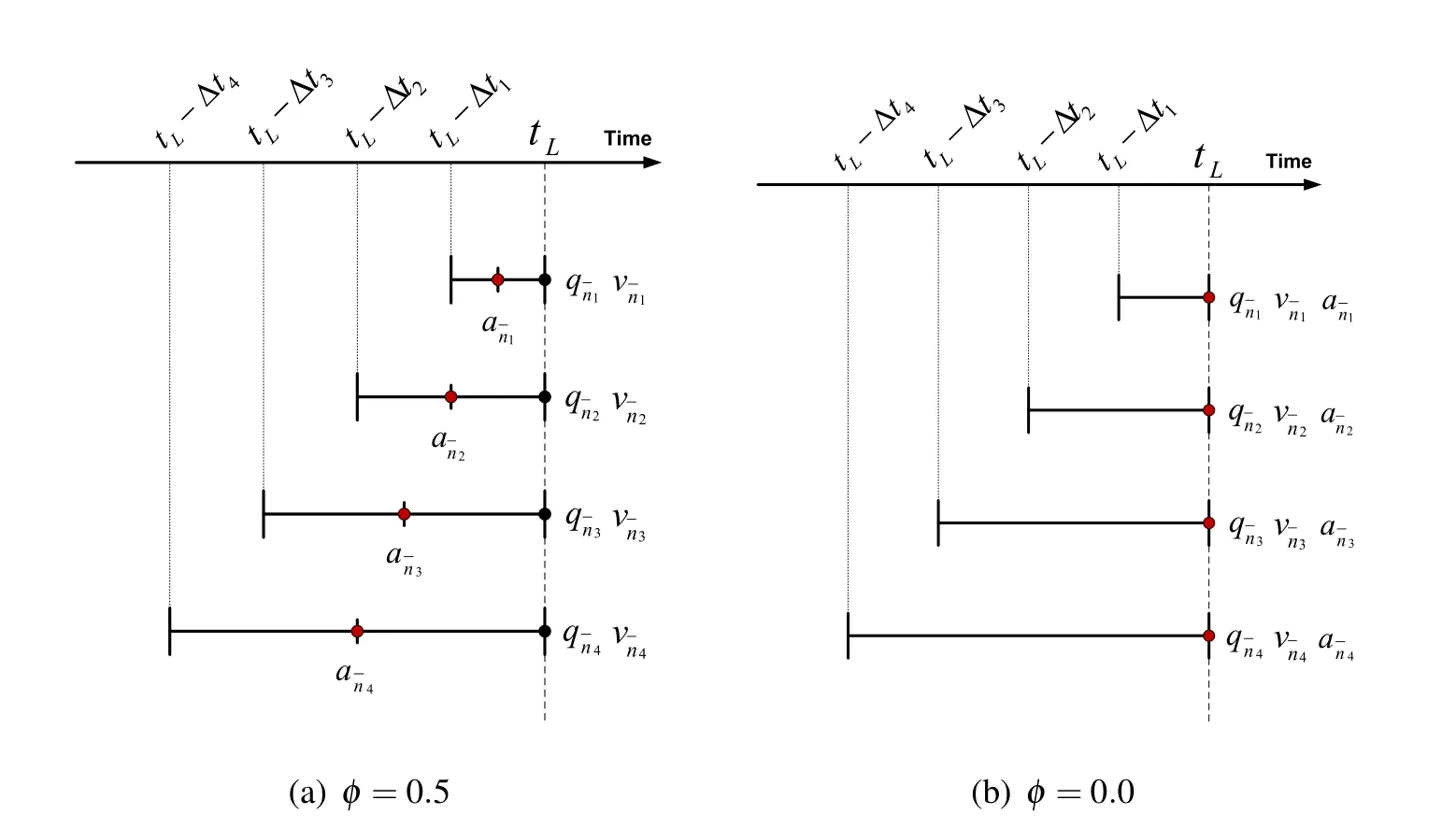
Figure 6:Examples of the final time steps used in creating a convergence plot when(a)φ=0.5 and(b)φ=0.0.For(a),the acceleration time level shift is required.
5 Numerical Illustrations
5.1 Single Degree of Freedom(SDOF)Example
Consider a single degree of freedom problem,¨q(t)+0.25˙q(t)+10q(t)=0 with given initial conditionsq0=q(0)=2 andv0=˙q(0)=2.For this system it was shown in Fig.1c for the V0U0(1,1,0)algorithm(MPR-MPA algorithm),the acceleration appears to be only first order accurate.Using the concepts described above,we are now able to understand why:the φ value for the V0U0(1,1,0)algorithm is 0.5.This means that the accelerations resulting from the algorithm do not align with the displacement and velocity,and care must be taken to properly represent the converge rate.Fig.7 shows the resulting convergence plot taking into account this shift;notice that now all three primary variables show the expected order of time accuracy.
To demonstrate that the above procedure indeed yields expected second order time accurate accelerations over the entire range of φ,four common algorithms which which include numerical dissipation in the U0 family of algorithms were selected as shown in Table 2.
For each of the four algorithms described above,convergence plots are shown using 4 numerical solutions.Two convergence plots were generated for each algorithm:one without accounting for acceleration offset and one in which accelerations were aligned via Eq.45.
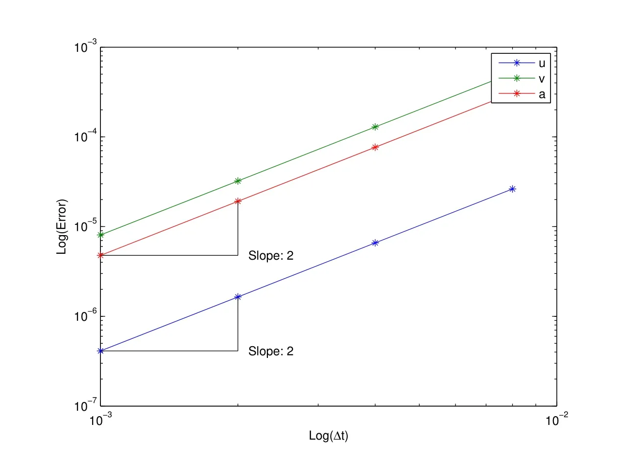
Figure 7:V0U0(1,1,0):MPR-MPA method-acceleration aligned convergence plot(see improvement and compare to Fig.1c)

Table 1:Selected algorithms from the U0 family for Figs.8 and 9 and Figs.11 and 12

Table 2:Selected algorithms from the V0 family for Figs.13 and 14
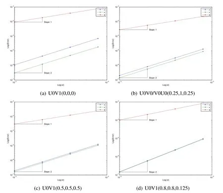
Figure 8:SDOF U0 family traditional convergence plots showing poor understanding
It is consistently shown in Figs.8 and 9 that in the traditional convergence plot the slopes of the displacement and velocity are 2.0 while the slope of the acceleration is 1.0.Once aligned correctly,the proper convergence plots now indeed show the acceleration has a precise slope of 2.0.
5.2 Nonlinear Tetrahedral Spring-mass System Example
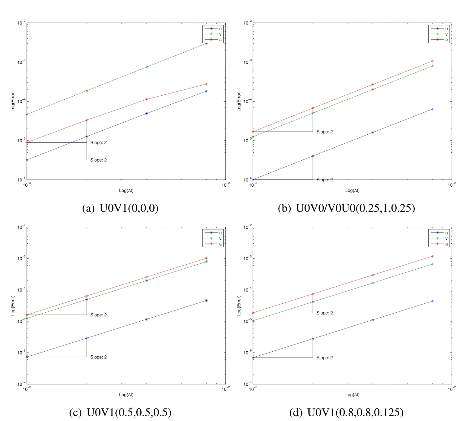
Figure 9:SDOF U0 family acceleration aligned convergence plots showing improved understanding of fundamentals
Consider another example,which is a tetrahedral spring-mass system depicted in Fig.10a constructed of six springs and four masses.Each spring has initial length of 1 m,stiffness of 103N/m,and mass 1 kg.The spring is characterized by geometrically nonlinear strain(Green strain).The initial position of the four nodes are[0.5,30.5/2,0,0,0,0,1,0,0,0.5,1/(2∗30.5),(2/3)0.5]T[m]with given initial displacement of[0,0.5,0.2,0,0,0,0,0.8,0,0,0,0]T[m]and initial velocity of[0,0,6,0,0,0,0,0,0,1,3,2]T[m/s].The dynamic responses of the system over a 5 sec time span with a time step size Δt=0.1 sec can be seen in Fig.10b.Figs.11 and 12 show the misaligned and aligned results that accurately describe the correct evaluation of accelerations,using the selected algorithms from the U0 family as shown in Table 1.Similarly,Figs.13 and 14 show the misaligned and aligned results that accurately describe the correct evaluation of accelerations,using the selected algorithms from the V0 family as shown in Table 2.Note that U0V0 optimal schemes and V0U0 optimal schemes are identical each other.
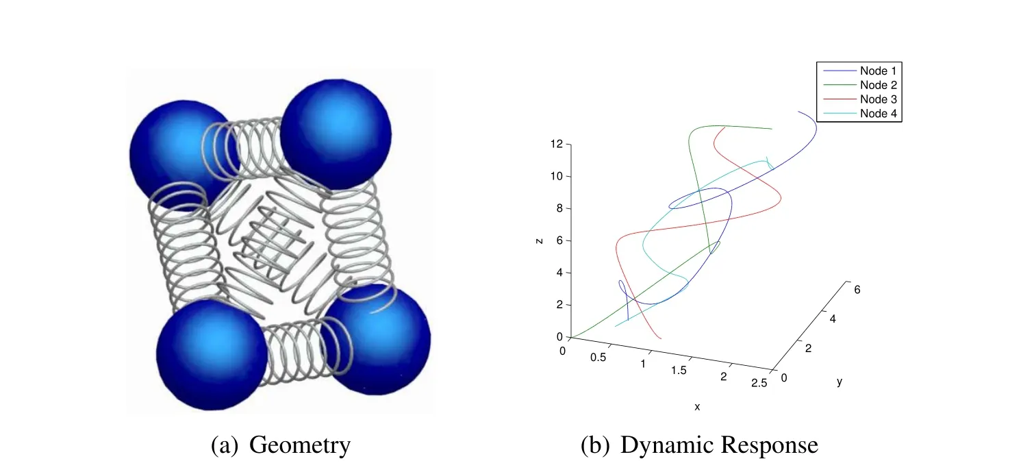
Figure 10:Tetrahedral spring-mass problem
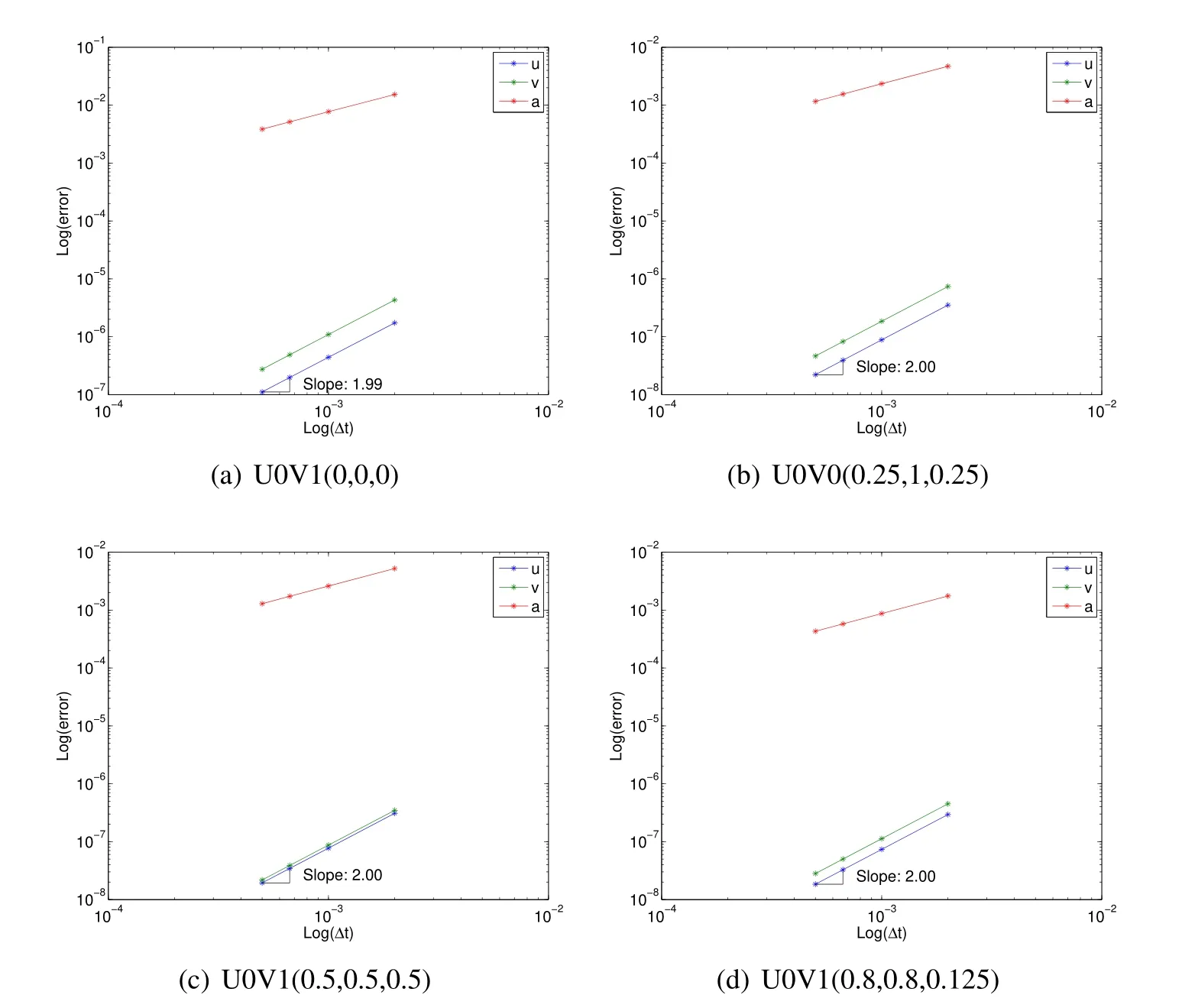
Figure 11:Tetrahedral spring-mass U0 family traditional convergence plots showing poor understanding
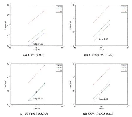
Figure 12:Tetrahedral spring-mass U0 family acceleration aligned convergence plots showing improved understanding of fundamentals
6 Conclusion
This paper described the accurate and precise evaluation of acceleration computations useful for structural dynamic simulations.The focus was upon the class of LMS methods which are predominantly used in most commercial and research software.They include numerically non-dissipative and numerically dissipative methods.An underlying theory regarding the time levels at which these computations need to take place precisely to achieve the desired order of time accuracy which is targeted at second order for the class of LMS methods was presented.The literature to-date lacks a theoretical basis on how to evaluate these acceleration computations accurately and precisely.The LMS methods have been developed under the umbrella of GSSSS algorithms which encompass most of the developments to-date and contain both numerically non-dissipative and numerically dissipative methods.The fundamental problem is that with the exception of the standard Newmark and midpoint rule,the acceleration computations of all the others are not trivial and the resulting computations to achieve second order accuracy are not strictly at time leveln+1.In this regard,we described the subtle issues and some noteworthy perspectives to accurately obtain the acceleration computations for general algorithms and the precise time levels that underlie their basic developments.We have provided a theoretical basis and an in-depth understanding to estimate accurately the accelerations and to ensure that they are all second order time accurate.Several simple numerical examples demonstrated the basic ideas.
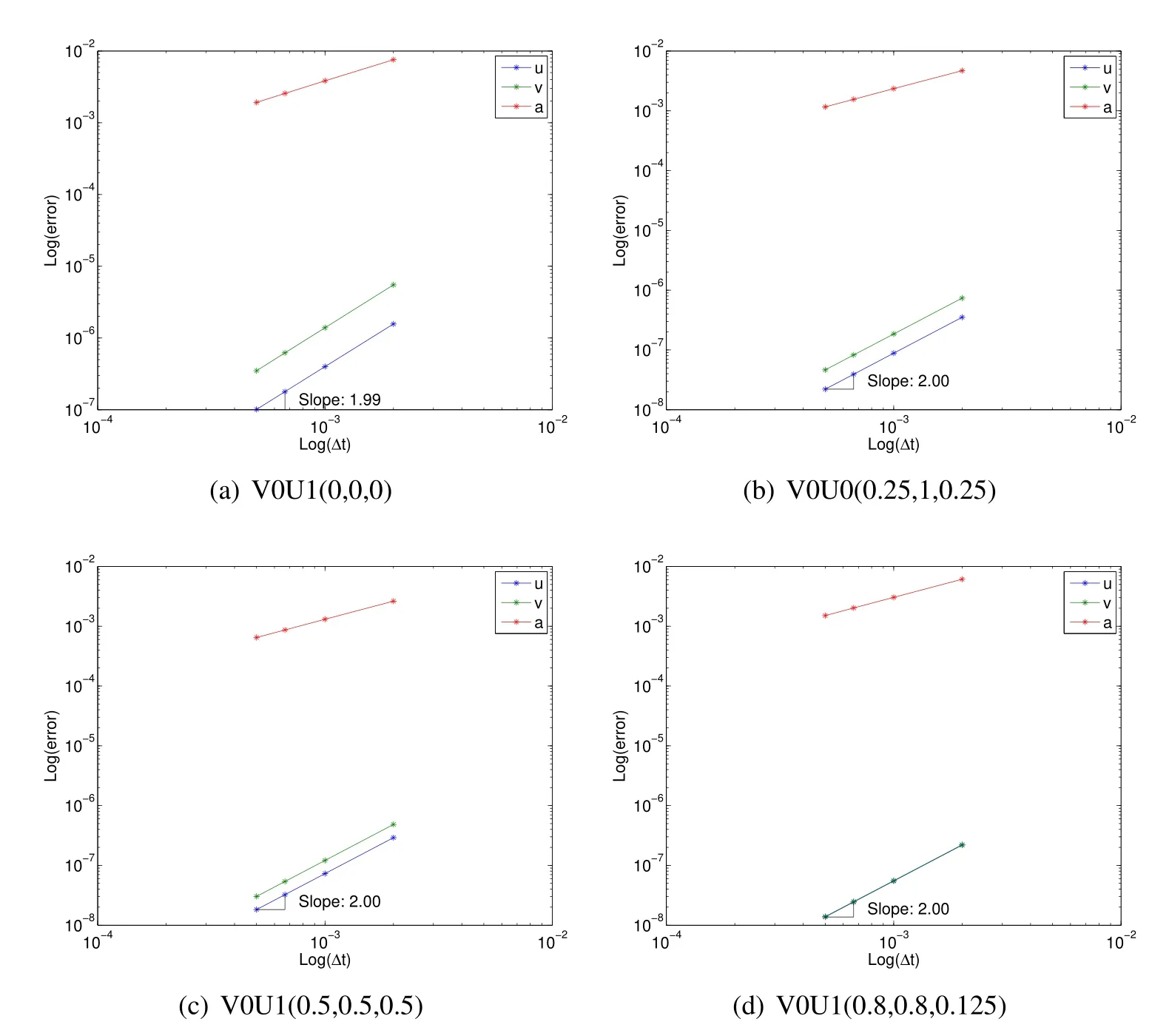
Figure 13:Tetrahedral spring-mass V0 family traditional convergence plots showing poor understanding
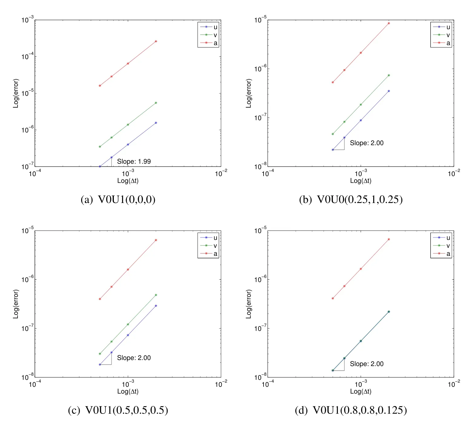
Figure 14:Tetrahedral spring-mass V0 family acceleration aligned convergence plots showing improved understanding of fundamentals
Acknowledgement:Other related support in form of computer grants from the Minnesota Supercomputer Institute(MSI),Minneapolis,Minnesota is also gratefully acknowledged.
Erlicher,S.;Bonaventura,L.;Bursi,O.S.(2002):The Analysis of the Generalized-α Method for Nonlinear Dynamic Problems.Computational Mechanics,vol.28,pp.83–104.
Har,J.;Tamma,K.K.(2012):Advances in Computational Dynamics of Particles,Materials and Structures.John Wiley,Chichester,UK.
Hilber,H.M.;Hughes,T.J.R.;Taylor,R.L.(1977):Improved Numerical Dissipation for Time Integration Algorithms in Structural Dynamics.Earthquake Engineering and Structural Dynamics,vol.5,pp.283–292.
Masuri,S.U.;Sellier,M.;Zhou,X.;Tamma,K.K.(2011):Design of Order-preserving Algorithms for Transient First-order Systems with Controllable Numerical Dissipation.Int.J.Num.Methods in Engr.,vol.88,pp.1411–1448.
Newmark,N.M.(1959):A Method of Computation for Structural Dynamics.Journal for American Society of Civil Engineers,vol.1,pp.67–94.
Shimada,M.;Tamma,K.K.(2012):Conserving/Dissipative Algorithms and Designs for a System of N Particles:Total Energy Framework and Single-Field Form.Computers and Structures,vol.112-113,pp.380–405.
Shimada,M.;Tamma,K.K.(2013):Implicit Time Integrators and Designs for Nonlinear Second-Order Transient Systems:Elastodynamics.Encyclopedia of Thermal Stresses,vol.5,pp.2409–2416.
Tamma,K.K.;Kanapady,R.;Zhou,X.;Sha,D.(2000):Recent Advances in Computational Structural Dynamics Algorithms.InSeventh Int-Conf.on Recent Advances in Structural Dynamics ISVR,Southampton,UK.
Tamma,K.K.;Namburu,R.R.(1990):Applicability and Evaluation of An Implicit Self-Starting Unconditionally Stable Methodology for Dynamics of Structures.Computers and Structures,vol.34,pp.835–842.
Tamma,K.K.;Zhou,X.;Sha,D.(2000):The Time Dimension:A Theory of Development/Evolution,Classification,Characterization and Design of Computational Algorithms for Transient/Dynamic Applications.Archives in Computational Mechanics,vol.7,no.2,pp.67–290.
Zhou,X.;Tamma,K.K.(2004):A New unified Theory Underlying Time Dependent Linear First-Order Systems:A Prelude to Algorithms by Design.International Journal for Numerical Methods in Engineering,vol.60,pp.1699–1740.Zhou,X.;Tamma,K.K.(2004):Design,Analysis,and Synthesis of Generalized Single Step Single Solve and Optimal Algorithms for Structural Dynamics.International Journal for Numerical Methods in Engineering,vol.59,pp.597–668.
Zhou,X.;Tamma,K.K.(2006):Algorithms by Design with Illustrations to Solid and Structural Mechanics/Dynamics.International Journal for Numerical Methods in Engineering,vol.66,pp.1738–1790.
CMES: Computer Modeling in Engineering & Sciences
Aims and Scope:This journal publishes original research papers of reasonable permanent value, in the areas of: computational mechanics, computational physics, computational chemistry, and computational biology, pertinent to solids, fluids, gases, biomaterials, and other continua. Various length scales (quantum, nano, micro, meso, and macro), and various time scales (picoseconds to hours) are of interest. Papers which deal with multi-physics problems, as well as those which deal with the interfaces of mechanics, chemistry, and biology, are particularly encouraged. New computational approaches, and more efficient algorithms, which eventually make near-real-time computations possible, are welcome. Original papers dealing with new methods such as meshless methods, and mesh-reduction methods are sought.
Manuscript Format & Style:References to the literature in the text should be by author and year;all the authors’ names should be spelled out; and the use of “et al” should be avoided at all costs.References should be listed in alphabetical order, at the end of the paper, as follows:
Atluri, S. N.; Nakagaki, M. (1986): Computational methods for plane problems of fracture. In: S.N. Atluri (ed) Computational methods in the mechanics of fracture, Elsevier, Amsterdam, pp.169-227.
Atluri, S. N. (2004):The Meshless Method (MLPG) for Domain & BIE Discretization. Tech Science Press, 680 pages, Forsyth, GA.
Illustrations:Photographs should be in focus, be of high contrast, and should not be lettered with a ball pencil, felt pen or ink. Colour illustrations will not be accepted in the printed version of CMES;however, they will be accepted in the online version of CMES. Line drawings should be supplied as clear black- and-white drawings suitable for reduction rates of 40-50%. Lettering should be of standard vertical type and large enough, so that, after reduction, it will not be less than 2 mm size.Submission of digital images is preferred, and strongly suggested.
Manuscript Typesetting:Authors are requested to submit electronic versions of the manuscripts,in order to facilitate an accurate typesetting. Papers (with both PDF and source files) must be uploaded electronically, at the website: http://submission.techscience.com/cmes. Detailed instructions for preparing the manuscripts, including the format and styles, can be down-loaded from the website: http://www.techscience.com/cmes. Authors are encouraged to use either the customized LaTex macro or the template for Microsoft Word, both of which can be down-loaded from http://www.techscience.com/cmes, to prepare the final version of their manuscripts. Authors are requested to submit their manuscript in LaTex source .les (including the non-standard macro packages used), or in Word Document Format, to facilitate an accurate typesetting. Authors may elect to submit two versions of manuscript, one for the printed version of CMES, and the other for the on-line version of CMES. Illustrations in colour may be used only in the on-line version of the manuscripts.
Proofreading:Proofs are sent to the corresponding author, to be downloaded from the journal’s website: http://submission.techscience.com/cmes. The corrected proofs should be returned within 48 hours and corrections limited to typographical errors. Any other changes in the text are expensive and will partially be charged to the authors. Corrections are to be done using internationally accepted symbols.
Offprints:Offprints may be ordered at cost price when the page proofs are returned. Tech Science Press will supply the corresponding author with 2 free copies of the relevant issue of CMES.
1Department of Mechanical Engineering,University of Minnesota,111 Church St.SE,Minneapolis,MN,55455,USA.
2Corresponding Author.E-mail:ktamma@umn.edu
2Algorithms within the U0 family and V0 family are generally expressed as U0andrespectively.

