A Macro Element Method to Improve Computational Efficiency in Large-scaled Nonlinear Analysis
2015-12-12 05:45HuanWangWeifengYuanandFeiJia
Computers Materials&Continua 2015年7期
Huan Wang,Weifeng Yuanand Fei Jia
A Macro Element Method to Improve Computational Efficiency in Large-scaled Nonlinear Analysis
Huan Wang1,Weifeng Yuan2,3and Fei Jia2
Compared with dealing with a linear system,solving a nonlinear system equation in numerical simulation requires generally more CPU time since iterative approach is usually used in the latter.To cut down the computing cost,a direct way is to reduce the degree of freedoms(DOF)of the problem under investigation.However,this kind of treatment may result in poorer accuracy.In this manuscript,a macro element method is proposed to improve computational efficiency in large-scaled nonlinear analysis.When this concept is incorporated into finite element analysis(FEA),all the members in the linear zones of a structure can be grouped into just one macro element.By using weak member approach,the stiffness matrix of this macro element can be evaluated through unit force method.Numerical examples prove that the proposed macro element method can increase the computational efficiency significantly without obvious negative influence on accuracy.
Macro element,nonlinear,computational efficiency.
1 Introduction
FEA is an important numerical tool to analyze various problems.It is well known that the computing cost in a FEA modelling is dependant on the number of degree of freedoms(DOF)in the FEA model under investigation.In numerical simulations,some algorithms including multi-domain method[Miao,Chen,Wang and Zhu(2014)]and static condensation method[Eom,Ahn,Baek,Kim and Na(2007)]are usually employed to achieve DOF reduction.In a large-scaled problem,a direct way to improve the computational efficiency is to limit the number of elements.However,some important details of the structural response may be sacrificed sincefewer elements may cause poorer accuracy[Lin and Donaldson(1969);Finnveden(1994)].Alternatively,superelement method is also widely used in FEA analyses for various problems[Lukasiewics(1987);Song(2004);Birgersson,Finnvedenand Nilsson(2005);Dong,Atluri(2012),(2013)].The original idea of superelement was introduced by aerospace engineers in the early 1960s to carry out a first-level breakdown of complex systems such as an entire airplane[Przemieniecki(1968)].Briefly,the basic concept of superelement method is to treat structural members as a continuous body and then discretize this body into superelements defined as any cluster of contiguous elements[Cao(1992);Jiang and Olson(1994)].In this way,each superelement may consist of different types of members which may have various shapes,materials properties and boundary conditions.
As a hallmark of practical application,superelement technique was incorporated into NASTRAN in the 1970s.The capability of superelement method was then tested and further developed[Zemer(1979);Jacobsen(1983)].Because of the most attractive advantage to significantly improve the computational efficiency,superelement method has been employed to analyze various problems in recent years.In summary,the problem characteristics which are suitable for the application of superelement can be summarized into three distinguishing features,viz.iterative computational tasks,localized nonlinearity and a large number of finite elements in the numerical models for applications in dynamics.At present,the methods to construct superelements are usually based on substructure and static condensation techniques[Wilson(1979);Chen and Pan(1988)].However,inconvenience may be caused in the conventional superelement techniques.For instance,to apply static condensation,many nodes in the mesh have to be renumbered,or the rows and the columns in the stiffness matrix have to be swapped to make the DOF associated with the superelement to lie in the upper left sub-matrix in the system stiffness matrix.Therefore,a macro element method based on superelement concept is proposed in this manuscript to overcome the limitations of the conventional superelement formulation.To implement this approach,an entire structure has to be divided into several linear and nonlinear zones according to the requirement of numerical investigation and the behavior of the structure.The main novelties of the proposed approach include(i):the algorithm is very simple to implemented,and(ii):the whole members in all linear zones can be grouped into just one super element,even in the case that the linear zones are not connected.
2 Methodology
2.1 Concept
Fig.1 shows a linear elastic system which contains two nodes A and B.Three load cases are discussed below:
Case 1:in Fig.1(a),a force p1is applied at node A along direction x1.At node B,the displacement vector induced by p1is denoted by[u11u21]T.
Case 2:in Fig.1(b),a force p2is applied at node A along direction x2.At node B,the displacement vector induced by p2is denoted by[u12u22]T.
Case 3:In Fig.1(c),two arbitrary forces,P1and P2are applied at node A simultaneously.At node B,the displacement vector induced by P1and P2is denoted by[U1U2]T.
According to the theory of linear system,[U1U2]T,the displacement vector in Case 3 can be evaluated based on Case 1 and Case 2.
Taking the forces at node A as input and the displacements at node B as output,Eq.1 can be used to describe the linear system.

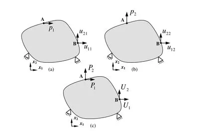
Figure 1:Illustration of force-displacement relationship in a linear elastic system.
From Case 1 and Case 2,one obtains:
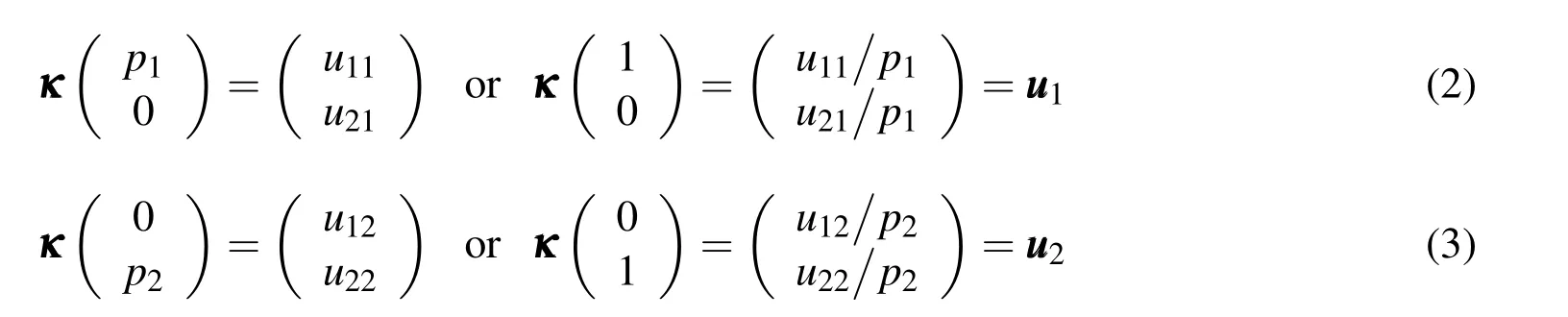
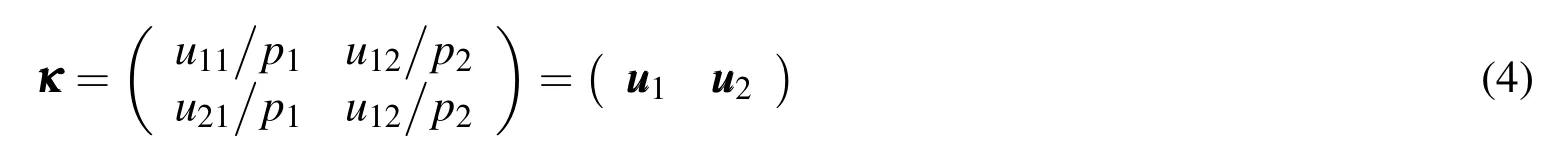
Therefore,for Case 3,U1and U2can be carried out:
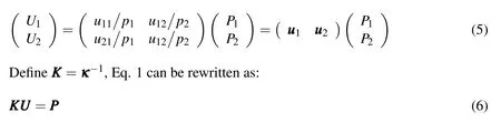
where KKK performs as a stiffness matrix.
From Eq.1 to Eq.6,one finds that KKK can be obtained by unit force method.
2.2 Derivation
In Fig.2(a),a structure with restraints(i=1,2,3,···,mL)and1,2,3,···,mN)is subjected to external loadsand1,2,3,···,nN).For finite element modelling,the structural domain is normally discretized into a cluster of elements,each element contains several nodes.Without loss of generality,it is assumed that there are five nodes on the boundary between the linear and nonlinear zones.In the linear zone,there is a typical node R that has NDDOF.The following four steps describe how to group the entire linear zone into a macro element.
1)Focus on the simulant structure of the original one
Fig.2(b)is the simulant structure of the one in Fig.2(a).Compared with the original structure,the simulant structure is under the same loadings and restraints.However,the nonlinear zone in Fig.2(a)is replaced by the overlapped zone in Fig.2(b).The overlapped zone consists of two parts,viz.the virtual weak part and the original nonlinear zone.The virtual weak part is the same as the original nonlinear zone in geometry,but the members in the virtual weak part are assumed to be elastic,with very low elastic modulus.
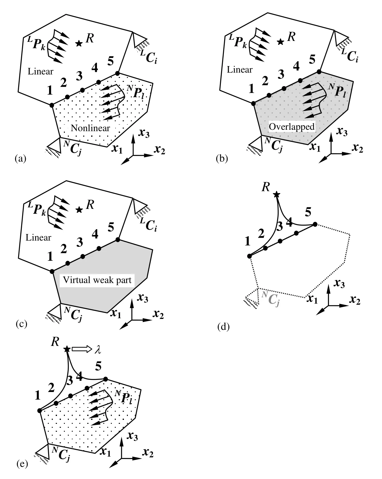
Figure 2:The procedure to group the linear zone into a macro element.
2)Define a macro element
The original nonlinear zone andNPPPl(l=1,2,3,···,nN)are all removed from Fig.2(b)to create Fig.2(c).In Fig.2(c),the linear zone and the virtual weak part form a fictitious linear structure.The system equation of a FEA model for the fictitious structure can be expressed by Eq.7:

In this equation,the subscript“f”denotes “ fictitious”. KKKfis the global stiffness matrix of the fictitious structure. UUUfand PPPfare the displacement and force vectors,respectively.Since the entire fictitious structure is elastic,Eq.7 is a linear equation.It should be noted that the entire fictitious structure restrained byLCiandNCi(i=1,2,3,···,m)performs as a stable linear system.Therefore,one can treat this structure as a continuous elastic body and convert it into a macro element.It should be noted that both the linear zone and the virtual weak part are modelled by a cluster of node-based elements in a numerical model.However,only six nodes are selected to form the macro element.The six nodes include R,the reference node,and the five joints shared by the linear and the virtual weak parts(Fig.2(d)).3)Evaluate the stiffness matrix of the macro element.
As mentioned,the macro element contains six nodes.Each node has NDDOF in the original FEA model for the fictitious structure.However,in the macro element,the DOF of the reference node R is set to 1 due to its special role.Each of the other five nodes still has NDDOF.Hence,the total DOF of the macro element is 5ND+1.Denoted by KKKm,the stiffness matrix of the macro element should satisfy the following equation:

In Eq.8,the subscript“m”represents “macro”. UUUmand PPPmare the displacement and force vectors,respectively.They are all(5ND+1)×1 vectors. KKKmis a(5ND+1)×(5ND+1)matrix.Based on Eq.7, KKKmcan be evaluated using unit force method.
Firstly,?for convenience,define a load case L0which indicates that..are applied to the macro element simultaneously.The scalar coefficient λ is used to adjust the magnitudes of the forces.In this study,it is recommended that λ=The superscript of L0denotes the load case number.Fromare all ND×1 vectors.In the superscript,the letter in front of the comma indicates the identitywhile the number behind the comma is for load case.For instance,means the displacement vector at node 3 due to load case L0.Similarly,the displacement at node R induced by L0is denoted byIn this study,the reason why R is selected to be “the reference node”is thathas a nonzero component.Without loss of generality,it is assumed that this nonzerothese forces are represented symbolically by a single unit force,which is applied at node R along the direction of thevectors at the five joints induced bySecondly,a unit load is applied along the first DOF direction at node 1 to create the load case L1.The correspondingjoints can be obtained.They are defined to berespectively.Similarly,a unit force is applied to nodethe load case L2and obtain the correspondingRepeat this procedure till a unit force is applied to node 5procedure,a typical load case Lkis created and(k=1,5ND)can be calculated using Eq.7.Thirdly,considering all the load casesand the corresponding displacements,one can obtain:
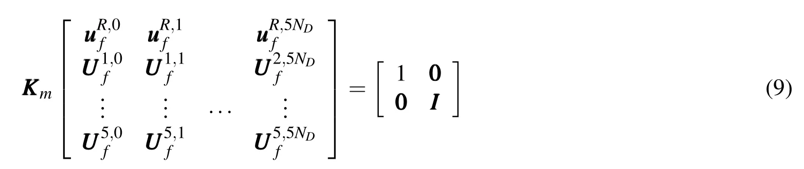
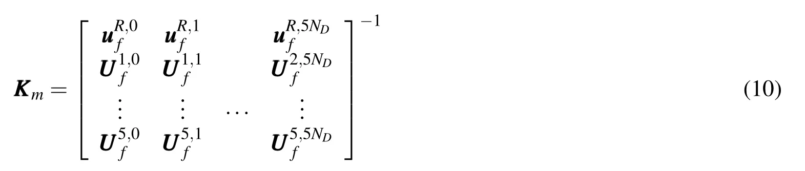
where K K Kmis a(5ND+1)×(5ND+1)matrix.
As shown in Fig.2(e),the macro element and the nonlinear zone form a simplified structure.The macro element contains six nodes,viz.node R and nodes 1~5.In this structure,the real external loadsLPPPj(j=1,2,3,···,n)are replaced by a fictitious force with a magnitude λ acting at node R while the boundary conditions in the linear zone are ignored since their effects have been considered in the stiffness matrix of the macro element.In the nonlinear zone,both the original boundary conditions and the external loads remain unchanged.Since the stiffness matrix of macro element is known,the global stiffness matrix of the simplified structure can be assembled easily using conventional FEA approach.
It should be noted that the structure shown in Fig.2(e)represents a nonlinear system.Compared with that of the original structure(Fig.2(a)),the DOF of the fictitious structure(Fig.2(e))is much less,so the computational cost for the original structure can be reduced.However,it must be mentioned that the numerical result based on Fig.2(e)is an approximation to that obtained from Fig.2(a).Theoretically,from the energy point of view,the difference between the two kinds of results can be limited by setting the stiffness of the weak part very small.
3 Examples
3.1 Demonstration of constructing a macro element
As shown in Fig.3,a very simple plane frame is taken as an example to demonstrate the procedure of constructing a macro element.The frame is evenly divided into 20 2-node two-dimensional beam elements.Each node of a beam element has three DOF,viz.two translations and one rotation.Two pointed forces and a bending moment are applied at nodes 3,9 and 21,respectively.It is assumed that in such a structure,the elements between node 6 and node 21 are within a nonlinear zone,while those elements between node 1 and node 11 are in a linear zone.This example shows how the elements in the linear zone are merged into a macro element.

Based on the model shown in Fig.4,both linear and nonlinear analyses can be conducted using conventional FEA algorithms.The DOF of the macro element is 4,so the total DOF of the modified FEA model is 34,which is much less than 63,the DOF of the original model.Therefore,by macro element method,the computational efficiency can be improved.
In this example,the dimension of the cross-section of each beam is set to 0.05×0.05.The Young’s modulus and the Poisson’s ratio are 1×10⁶and 0.3,respectively.The loads applied to the original frame are P1=P2=1 and P3=0.1.The deformation of the frame is calculated by the present macro element method and the conventional FEA,through generalized displacement approach.During the analyses,both λ and P3increase gradually and the load-displacement curves are depicted in Fig.5.The analysis stops when the load factor is up to 40.
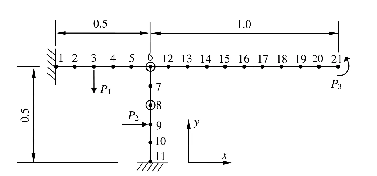
Figure 3:A two-dimensional frame subjected to external forces.
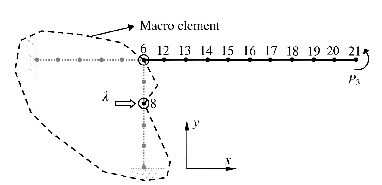
Figure 4:A two-dimensional frame with a macro element.
From Fig.5 it can be seen that the results obtained by the two methods have very good agreement.However,as the load factor increases,the variation between the two types of results becomes larger.This is because the nonlinearity behaviour of the beam members involved in the macro element becomes obvious when the load factor is large enough.Actually,such a situation conflicts with the basic assumption of the linearity in the macro element method.
3.2 Investigation on the computational efficiency
A two-storey steel frame is described in Fig. 6.The dimension of the cross-section of each member is set to be 0.1m×0.1m.Without macro element, the entire structureis divided into 40 3-dimensional 3-node fibre-beam elements[Spacone, Filippouand Taucer (1996)]. Each beam cross-section is divided into 100 segments.The loads applied on the original frame is P0 = 100kN. The material properties are as follows.
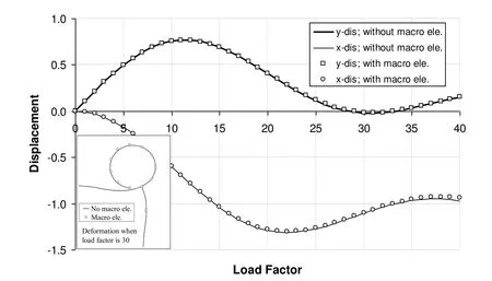
Figure 5:Comparison between two kinds of load-displacement curve.
Fig.6 also shows that the first storey of the original structure is grouped into a macro element.Since the two storeys have only two joints,viz.nodes B and C,the macro element consists of three nodes.Without loss of generality,node A is selected to be the reference node.For this example,two types of nonlinear simulation for the original and simplified FEA models are conducted on a Pentium Dual-Core PC(CPU E6700@3.20GHz),based on the generalized displacement approach.During the analyses,both geometrical and material nonlinearities are taken into account.The maximum number of the steps for load increment is set to be 1000.The numerical test proves that the computational efficiency can be improved significantly by using the proposed macro element method.The CPU time consumed in the analysis with macro element is only 25%(2771ms vs.11095ms)of that used in the analysis without macro element.Further comparison is depicted in Fig.7.It is observed that the deflection at node M increases as the external load becomes larger.The two load-deflection curves are very close which means that the result obtained by the proposed macro element method is accurate if the members grouped into the macro element do not in the first place behave nonlinearly,or the extent of nonlinear response is limited.
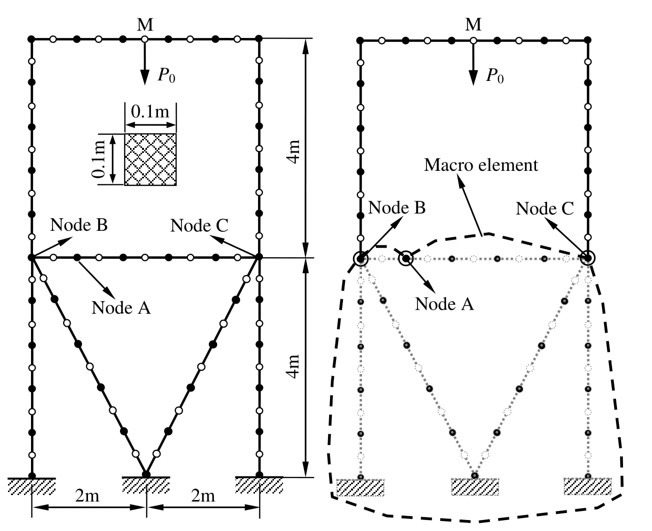
Figure 6:A two-storey frame is analyzed using macro element method.
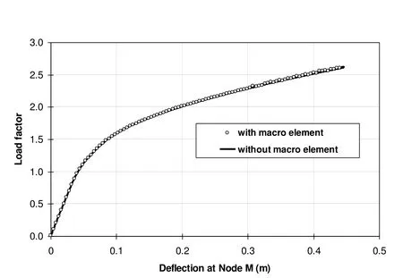
Figure 7:Comparison between the displacements at node M.
4 Conclusions
This paper proposes a macro element method to simply nonlinear FEA analysis.Using the present method,the DOF of a large-scaled structure can be reduced significantly.Through the definition of virtual weak part,the structural members in the linear zones can be grouped into just one macro element regardless whether the linear zones are connected or not.Numerical examples demonstrate the construction of a macro element and verify the correctness of the proposed method.It can be concluded that the macro element method is easy to be implemented and it has great potential in the simulation of large-scaled complex structures.It must be mentioned that the two examples given in this paper are all geometrical nonlinearity problems.However,the formulation presented in this study is applicable to material nonlinearity problems as well.Unlike that of a conventional FEA model,the stiffness matrix of a macro element may not be symmetric.This may cause additional requirement for CPU time.On the other hand,the overall calculation may still be much more efficient since the total DOF of the original FEA model can be reduced significantly by the current macro element method.
Acknowledgement: This work is sponsored by Southwest University of Science and Technology,through the fundings(i)Modelling of Dynamical Complex System(12xz7105)and(ii)DDA-BEM Coupling for Metal Cutting(13zxzk05).The support from SWUST is acknowledged by the authors.
Birgersson,F.;Finnveden,S.;Nilsson,S.M.(2005):A spectral super element for modelling of plate vibration,part 1:General Theory.Journal of Sound and Viberation,vol.287,no.1-2,pp.297-314.
Cao,Z.Y.(1992):Super element method for complex structure analysis.Mechanics and Practice,vol.14,no.4,pp.10-14.
Chen,S.H.;Pan,H.H.(1988):Guyan reduction.Communications in Applied Numerical Methods,vol.4,no.4,pp.549-556.
Dong,L.;Atluri,S.N.(2012):SGBEM(using non-hyper-singular traction BIE),and super elements,for non-collinear fatigue-growth analyses of cracks in stiffened panels with composite-patch repairs.CMES:Computer Modeling in Engineering&Sciences,vol.89,no.5,pp.415-456.
Dong,L.;Atluri,S.N.(2013):Fracture&fatigue analyses:SGBEM-FEM or XFEM?Part 1:2D structures.CMES:Computer Modeling in Engineering&Sciences,vol.90,no.2,pp.91-146.
Eom,K.;Ahn,J.;Baek,S.;Kim,J.;Na,S.(2007):Robust reduction method for biomolecules modeling.CMC:Computers,Materials&Continua,vol.6,no.1,pp.35-42.
Finnveden,S.(1994):Exact spectral finite element analysis of stationary vibrations in rail way car structure.Acta Acustica,vol.2,pp.461-482.
Jacobsen,K.P.(1983):Fully integrated superelements:a database approach to finite element analysis.Computers and Structures,vol.16,no.1-4,pp.307-315.
Jiang,J.;Olson,M.D.(1994):Nonlinear analysis of orthogonally stiffened cylindrical shells by a super element approach.Finite Elements in Analysis and Design,vol.18,pp.99-110.
Lin,Y.K.;Donaldson,B.K.(1969):A brief survey of transfer matrix techniques with special reference of aircraft panels.Journal of Sound and Vibration,vol.10,pp.103-143.
Lukasiewics,S.A.(1987):Geometrical super-elements for elasto-plastic shells with large deformation.Finite Elements in Analysis and Design,vol.3,pp.199-211.
Miao,Y.;Chen,Z.;Wang,Q.;Zhu,H.(2014):Mechanical analysis of 3D composite materials by hybrid boundary node method.CMC:Computers,Materials&Continua,vol.43,no.1,pp.49-73.
Przemieniecki,J.S.(1968):Theory of Matrix Structural Analysis,Mc Graw-Hill Publication,New York.
Song,C.(2004):A super-element for crack analysis in the time domain.International Journal for Numerical Methods in Engineering,vol.61,no.8,pp.1332-1357.
Spacone,E.;Filippou,F.C.;Taucer,F.F.(1996):Fibre beam-column model for non-linear analysis of r/c frames:part I.formulation.Earthquake Engineering and Structural Dynamics,vol.25,no.7,pp.711-725.
Wilson,E.L.(1979):The static condensation algorithm.International Journal for Numerical Methods in Engineering,vol.8,no.1,pp.198-203.
Zemer,D.T.(1979):Implementation of superelement analysis at the production level.Proceeding of the MSC/NASTRAN Users’Conference,Munich,Germany.
1School of Applied Technology,Southwest University of Science and Technology,China.
2School of Manufacturing Science and Engineering,Southwest University of Science and Technology,China.
3Corresponding author.E-mail:yuanweifeng@swust.edu.cn