
Bending Response of Foldcore Composite Sandwich Beams
2015-12-12 05:45LixinCongYuguoSun2andXinzhuWang
Computers Materials&Continua 2015年7期
Lixin Cong,Yuguo Sun,2and Xinzhu Wang
Bending Response of Foldcore Composite Sandwich Beams
Lixin Cong1,Yuguo Sun1,2and Xinzhu Wang3
In order to solve bending behavior difference of corrugated structure in L and W orientation,bending response for composite sandwich beams with foldcores of three different wall thicknesses were experimentally and numerically investigated.Effect of the cell walls thickness on the strength and failure behavior of the composite sandwich beams with L and W orientations was also examined.The deformation mode was obtained by the numerical method;a constitutive law of laminated material has been incorporated into a finite element(FE)analysis program.Numerical calculations give accurate prediction to the bending response of foldcore composite sandwich beams comparing with experiments.Structural flexural stiffness,strength and failure mechanism at a given topological geometry depended on the nature of core itself:the bending stiffness and strength of the sandwich beam increased with the core wall thickness(relative density).Also,bending isotropy was shown in this study for foldcore composite sandwich beams with selected core geometry.
Foldcore,Composite sandwich beams,Bending response,Failure behavior.
1 Introduction
Sandwich beams with two stiff faces carrying in-plane loads and out-of-plane bending separated by a lightweight cellular core which transferred the shear loads seen Allen(1969).Composite sandwich beams are widely used as components in aerospace and marine applications due to their outstanding stiffness and strength combined with low weight by Vinson(1999).Typically,cores are the weakest part of sandwich structures,and they fail due to shear.Ashby(2010)give understandingthe shear strength properties of core played an important role in the design of sandwich structures subjected to flexural loading.It recognized that sandwich beams bending stiffness and strength were strongly dependent on loading conditions,basis materials and specimen geometries Zenkert(1995).The three-point bending behavior of sandwich beams with diverse cores have been extensively investigated;these core materials include honeycomb cells[Belouettar et al(2009)],foam[Steeves and Fleck(2004)],corrugated[Jin et al.(2013)]and truss cores[Finnegan et al.(2007)].The results showed that the dominated failure modes of honeycomb and foam sandwich beams are core walls shear buckling,bending anisotropic behaviors appeared in corrugated plates.
In order to overcome these drawbacks,in recent years,a new generation of core materials was developed,which is foldcore.To date,composite sandwich panel with foldcore has been a quite young subject with regard to that with honeycomb or foam core.Many features are still waiting to be discovered.As well as mechanical requirements,core materials may also be selected based on their muggierresistance or thermal properties.Although mechanical behaviors of foldcore sandwich structure under static and dynamic loads have been investigated by different researchers[Fischer et al.(2009)],contains the transverse compression[Kintscher et al.(2007)],shear[Lebée and Sab(2010)]and end compression–bending behavior[Sturm et al.(2014)],in particular,experimental results on woven fabric composite foldcore loaded under impact[Heimbs et al.(2010)]have been extensively reported.When compared to traditional honeycomb and foam panels,foldcores offer several advantages.They can be made into wedged shapes[Zakirov et al.(2010)],allowing taller in-plane shear designed and higher resistance to damage from water intrusion,which could be important for bending applications.However,the data on bending loading are limited and are generally referred to Kraft paper[Basily and Elsayed(2005)]and aramid[Klaus and Reimerdes(2009)]foldcore rather than to composite panels.
This study will fill this gap in understanding glass fiber reinforced composite foldcore sandwich beams,particularly in effects of cell orientation(L or W)and cell wall thickness on bending properties of GFRP folded sandwich beams.Both experiments and numerical analysis will be carried out and failure mechanism will be analyzed.
2 Material and Experiment
Commercially available unidirectional glass fiber reinforced prepreg and adhesive film is used in this study;their mechanical properties are shown in Table 1.This prepreg is processed by the direct impregnated technique that fabric reinforcement has been pre-impregnated with a resin system.The plain weave has an average areal weight of 300 g/m2and cell wall thickness of the 0.12mm.
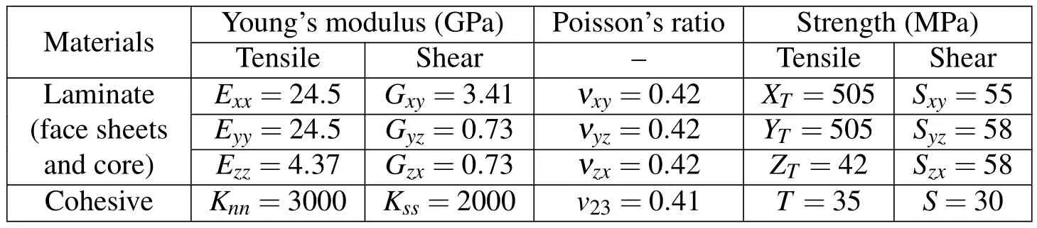
Table 1:Mechanical properties of laminate and adhesive materials.
Typical macroscopic view of the foldcore is shown in Figure 1.Pattern of the foldcore is chevron;geometric dimensions of the core is as shown in Figure 1a),this cell comprised four parallelogram sheets inclined at α,β and length of a side a,b,this structural behavior can be compared with Warren’s truss beams(Figure 1a),hence;the lower bound depends only on the member angle α and is maximum for α = π?4 as for Warren’s truss beams.The specimen’s geometry in bending tested is shown in Figure 1b),the face sheet was selective thickness tf=1.5mm;the three patterns of cores are named A,B and C(walls’thickness:0.24,0.48 and 0.72 mm,respectively),be to investigate the effect of wall’s thickness on the bending properties of the beam specimens.
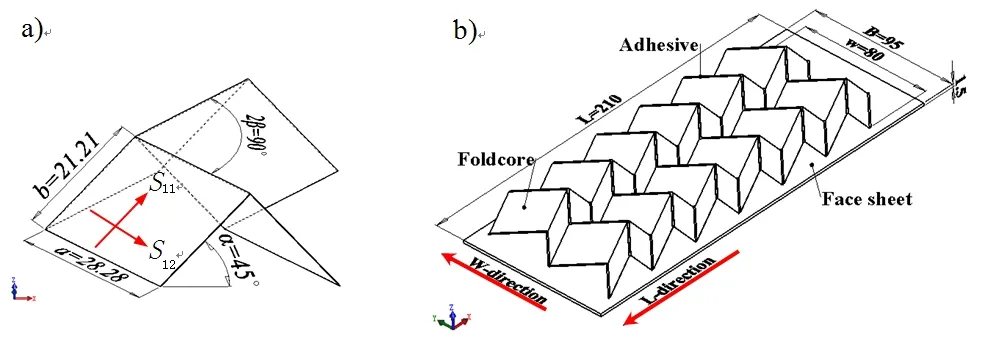
Figure 1:Sketch of the folded sandwich beam used bending test.a)Geometry of unit cell and def i ned to wall stress S11,S22,b)Sandwich-core nomenclature showing L and W−directions.
The composite face-sheet and folded core are manufactured using the same route,as die hot-press molding method,cured at temperature 80 ˚C/0.5h+120˚C/1.5h with 0.5MPa pressure.The sandwich beams assembled cores bonded to face sheet using an adhesive film(J-272)with epoxy resin as shown in Figure 1b),bonding at temperature 120˚C with 0.5MPa pressure for 1.5h.Finally,beams were water-jet cut to the required specimen size,illustrate both the L and W-direction for the sandwich beam,respectively.Here L is the beam spans between the supports,B the width of the beam,hcis the core thickness,and tfthe face thickness.
The global dimension of the foldcore sandwich beam specimen is shown in Figure 1.The relative density¯ρ is defined as the ratio of the density of the cellular core ρ∗,to that of the cell wall material ρS.The relative density can be expressed as follows:
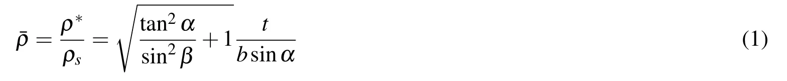
where t is the thickness of the inclined walls.
Bending tests were performed on three foldcore sandwich beams with different relative densities(2.7%,5.52%and 8.28%,respectively).The steel indenters(15.0×20.0mm)are used to apply the indentation load.The experiments are performed on an electromechanical testing machine(INSTRAN-5569)in a constant indenter displacement rate of 1mm/min at room temperature(23˚C)and the load and displacement data were recorded and analyzed.At least five samples are tested for each type of specimens.To minimize the effects of friction,the indenters were lubricated with PTFE spray.The three-point bending testing setup is shown in Figure 2.
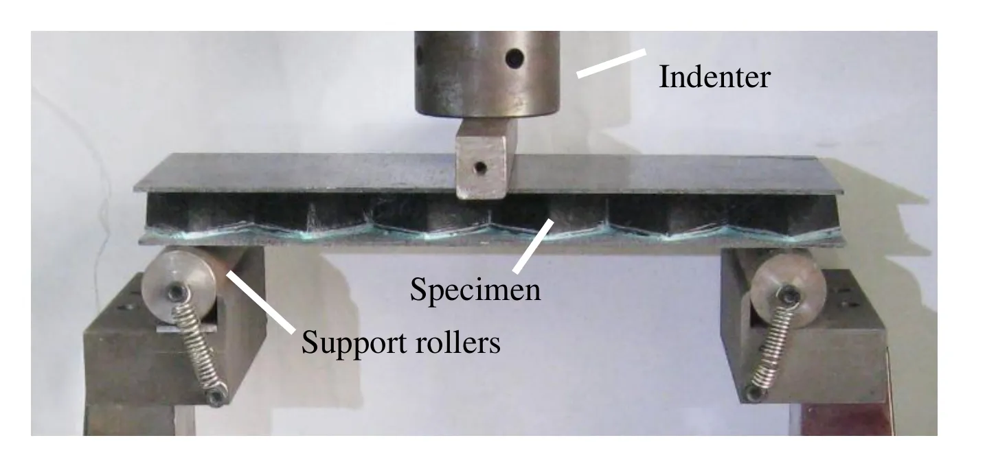
Figure 2:Bending test setup of foldcore sandwich beam.
3 FE model
Due to the practical limitations,the displacement and contact stress distribution cannot be measured;the numerical method is employed for the simulation of the bending process.The main purpose of the FE analysis was to predict the bending behavior of beam under the indenters.An FE model mimicking the geometry,loading and boundary conditions of the bending test are developed with the commercial FE code ABAQUS/standard.Features such as non-uniform distribution of cell size and cell wall imperfections,which may lead to local softening associated with the individual cell collapse,are not modeled by the FE code with a macroscopic model.
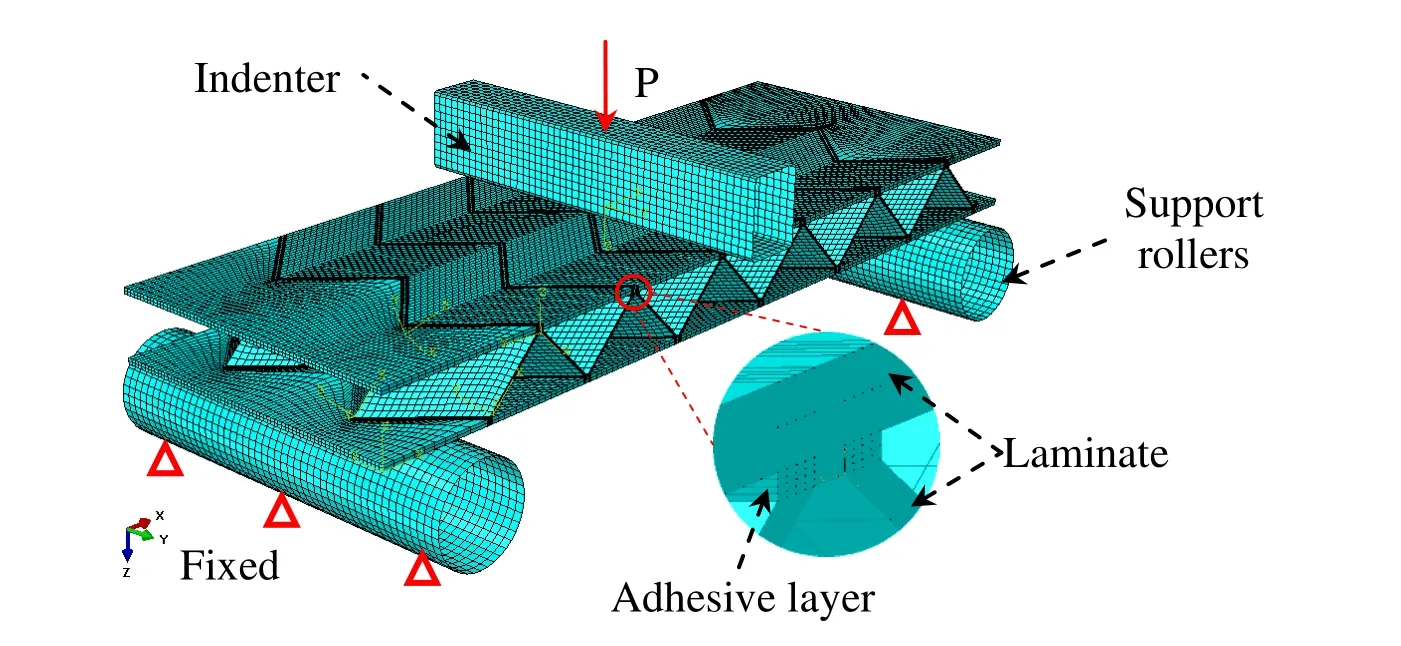
Figure 3:FE model of a folded sandwich beam under three-point bending load.
The solid and shell elements are used;contact has been defined at the indenter and the sample surface with refined mesh.The indenter was modeled as rigid surface,which cannot overlap in space of the beam.The mesh was well-tested for convergence and was determined to be insensitive to far-field boundary conditions.The contact was modeled as friction and large deformation FEM computations were performed.The bottom surface is held fixed in the loading direction;symmetry boundary conditions are applied to the cut faces of the quadrant while the remaining edges are unconstrained.
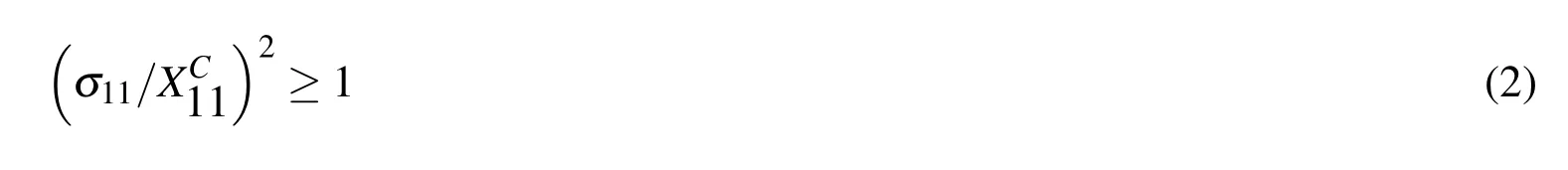
Failure analysis of the laminated walls by using a Hashin failure criterion,a summary of this criterion is provided below.
The compressive fiber is(σ11< 0):
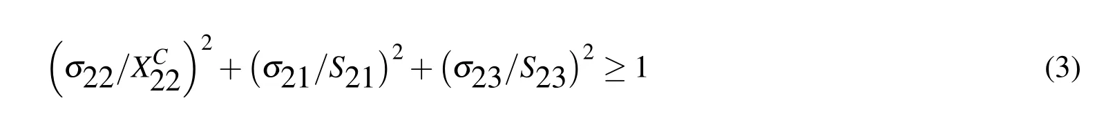
The compressive matrix is(σ22 <0):
The matrix and fiber shear is(σ11 <0)
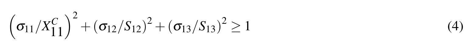
where 1 and 2 represent on-axis and σij(i,j=1,2,3)is the on-axis stress components in each laminate.The Hashin criterion has been programmed as a subroutine which is called from within the Fortran-coded user material subroutine(USDFLD).The generalized tractionseparation behavior is selected to represent the interaction between the face sheet and the core.The elastic behaviour is written in terms of an elastic constitutive matrix that relates the normal and shear stresses to the normal and shear separations across the interface.
The nominal traction stress vectort consists of three components:tntsand tt,which represent the normal(along the local 3-direction)and the two shear tractions(along the local 1-and 2-directions),respectively.The corresponding separations are denoted by δnδsδt.The elastic behaviour can then be written as:
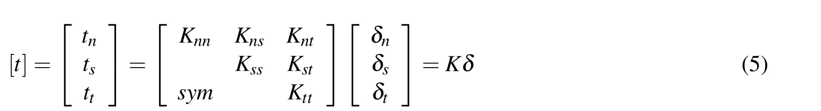
In the current study,the normal and tangential stiffness components will not be coupled.Consequently,the off-diagonal components of the stiffness matrix(K)relating to the traction to separation are zero.The non-zero values of diagonal components of the stiffness matrix were chosen as default values in ABAQUS.
It is assumed that the initiation of the damage process can be predicted using the quadratic failure criterion,considering that compressive normal tractions do not affect delamination onset and using the operator de?ned in(6):
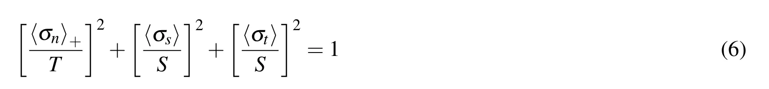
where,σn−interface tensile stress;
σs,σt−interface shear stress;
T,S−tensile and shear strength.
Damage modelling is required to simulate degradation and progressive failure of the bonding surfaces,the variation of fracture toughness as a function of a mode ratio in adhesive film,the B-K criterion based the mixed-mode criterion proposed is used here.This criterion is expressed as a function of the Mode I and Mode II fracture toughness,
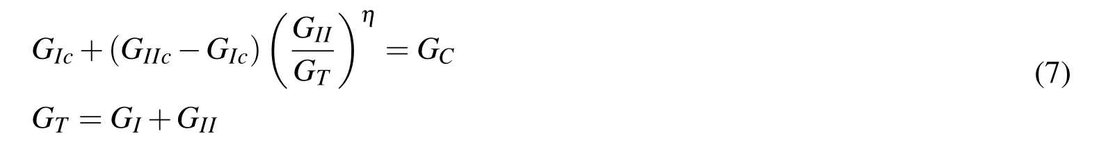
where,GIc,GIIc—interlaminar fracture toughness in I and II Modes,the B-K parameter η=1.7 is obtained from MMB tests at different mode ratios based on previous investigations by Camanho(2002),a penalty GIc=0.96 and GIc=1.719 is used here.
4 Results and discussion
The detailed comparison’s studies between the FE predicted and measured of the three-point bending response of the sandwich beams.The measured(denote by solid lines)and FE-predicted(denote by dotted lines)bending loads/displacement curves of the simply supported sandwich beam is drawn.In general,in order to validate the FE models,the boundary conditions applied in the FE models should mimic the loads applied in the experimental setup.Additionally,a deformation profile at different displacement levels by FE-predicted can be compared with measurement photos of the sandwich beam specimen.
4.1 Sandwich beam marked as A
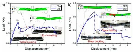
Figure 4:Response of the simply supported sandwich beam A with the folded core under both a)the L-,b)W-direction bending loading.
The load–displacement curves with the two different orientations and images at significant stages in the deformation are presented in Figure 4.In most cases,the limit loads measured on the two equivalent panels are consistent and deformation modes are the similar.
a)L-configurations
The initial linear-elastic behaviour(point ①)is followed by an elasto-plastic phase corresponds to overall core-walls compression buckling configurations until a peak value reached(point ②),after which the load decreases,initially markedly(points ③)by compression instability of the core in dextral end support and then more smooth(points ④),energy dissipation occurs due to the formation of plastic hinges which takes place along two different sections of the sample.
b)W-configurations
The initial linear-elastic behaviour(point ①)is followed by an elasto-plastic phase corresponds to overall core-walls shear wrinkling configurations until a peak value reached(point ②).The load loss after the peak value(point ②)is much more evident(point ③)due to failure always occurs by core shear(core shear failure along the side ridge at the contacted wall).Then more smooth(points ④),energy dissipation occurs due to the local interfacial debonding between face sheet and core.The primary results of the finite element simulation are summarized in Figure 4,the simulations capture most of the details of the deformation patterns quite realistically,including sharing of the core and buckling of the face sheets.
4.2 Sandwich beam marked as B
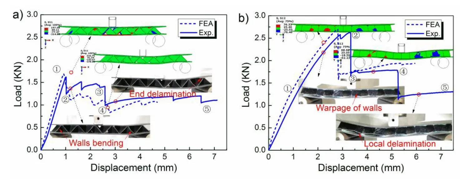
Figure 5:The bending response of the simply supported sandwich beam B with the foldcore under both the a)L-and b)W-direction bending load.
a)L-configurations
The folded sandwich B is different from the above sandwich beam A,wall buckling mode was none observed in W-direction bending tests(see Figure 5a).This effect is clearly observable in the load–deflection curves:the initial linear-elastic behavior until a peak value is reached(point ①),followed this load abrupt loss(points ②)due to the walls buckling occurs at the right support,subsequently serial minor stepped load loss by the initiation of interfacial debonding(point ③).
b)W-configurations
The initial linear-elastic behavior(point ①)is followed by an elasto-plastic phase with walls shear bending until a peak load reached(point ②),the inclined walls of the core is twisted under this condition.After which an stepped load decreases,the premature failure of the weak adhesive in the near vicinity of the left side support roller,a caused by the high peeling stresses at the face sheet–lower core interface,each load abrupt loss energy dissipated by a interfacial debonding(points ③-④),as shown in Figure 5b,followed by an almost constant load(point ⑤)by face sheet,stress of the deformation plateau keeps at the level of 1.0 MPa,nearly a half of the peak stress.Failure always occurs by only one mode(interface debonding)in transverse bending tests.
4.3 Sandwich beam marked as C
The typical load–deflection curve and different key features are clearly identified of sandwich sample C as shown in Figure 6.
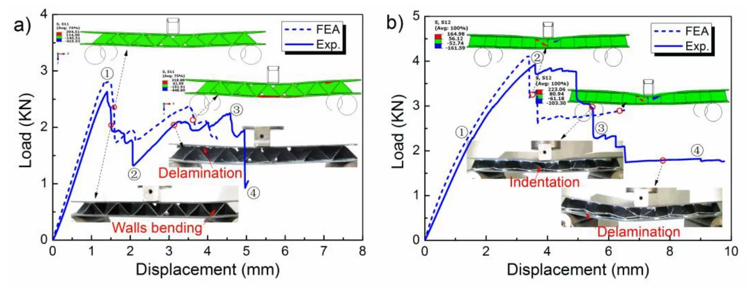
Figure 6:The bending response of the simply supported sandwich beam C with foldcore under both the a)L-and b)W-direction bending load.
a)L-configurations
The beam C having the densest core was the stiffest and had the largest rupture load.Observing the deformational behavior,we can identify the following characteristics:
As far as the sandwich beam C in the L-direction,bending is concerned,compressive stress(FEA:S11)of the walls is strong enough anti-compression deformation of the foldcore.Before the peak load(point ①)period,the load-def l ection curve of beam C with compressed bent walls shows a linear-elastic behavior,as shown in Figure 6a).Followed,the asymmetrical interfacial debonding between the upper face sheet and core was observed,this lead to a sudden load drop accompanied by a loud noise(point ②).The load increased due to the lower face sheet and the stiff core were still adhered together between the indenter and left rollers(point ③),until degumming of the upper face sheet large area occurs,load carrying capacity of the beam at δ≈5.1mm(point ④)is slowly loss.
b)W-configurations
In the W-direction,the in-plane shear stress is strong enough to anti-compression shear deformation(as:S12)of the walls.Good agreement between the predicted and observed deformation is obtained in terms of both the side views of the sandwich beam and the deformation of the beam at mid-span.The initial linear elastic(point ①)inloads displacement curve,followed nonlinear elasto-plastic phase with core shearing until a peak load(point ②),the bending stiffness decreases.During following phase,the load decreases,energy is mainly dissipated by symmetric indentation with the plastic hinges of upper face sheet under the loading roller(points ③),foldcore with compressive yielding have almost completely collapsed.Bending load further drops by a local debonding between the face sheet and core on the tensile side of the beam,resulting upper face sheet indentation disappeared,the may be due to complete debonding lead to the release of interfacial stress,afterward(points ⑤)bending load of beam level at 1.75 KN(points ④).The GFRP face sheet is more flexible than a CFRP face sheet,and which presents a larger local deformation under the load leading to core failure more easily than in CFRP.In fact,if the face sheet was very rigid,the indentation failure would be difficult to realize.
The work out the energy absorption bases in the area under the load-displacement traces shown in Figure 4-6,to compare and evaluate the energy absorption performance between the two bending tests.The energy absorption of L-direction structure with thin wall(0.24mm)occurred compression buckling is higher than the W-direction structure with walled shear buckling.The energy absorption of structure with thick walls(0.48,0.72mm)just is reverse.This is mainly due to deformation in L-direction of core with thick walls is a very small,core just support and interval the both face sheets,W-direction core with the walled shear buckling to absorbed more energy.
4.4 Comparison of measurements and predictions
To evaluate the wall thickness influence on the bending properties of the structure,where non-dimensional treatment technology is adopted,the specific stiffness and energy absorption of sandwich structure with three wall thickness core is shows Figure 7.The energy absorption value get by the area integral in the load-deflection curve as shown in Figure 4-6,specific energy absort by ratio of energy and relative density be defined.
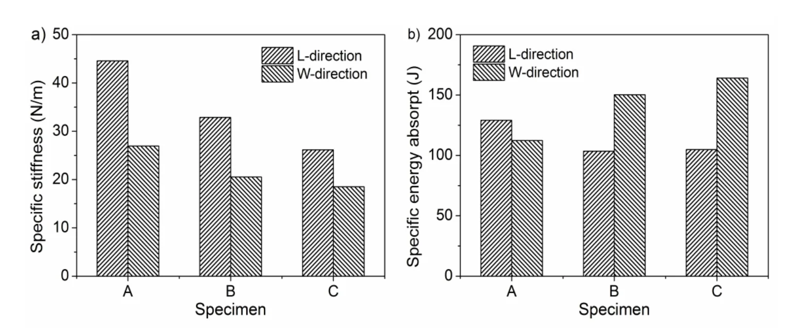
Figure 7:The Non-dimensional mechanical properties of the sandwich beam with foldcore the a)Specific stiffness and b)Specific energy absorpt.
The specific bending stiffness of beams decreases with the increase of relative density,such as Figure7a);The flexural stiffness is mainly composed tensile stiffness of a face sheet,shear stiffness of core has a little effect on the bending stiffness.The flexural stiffness is higher in L-configuration than in the W-configuration for the same sandwich core,this corresponds to walled stress(compressive stress S11for L-configuration and shear stress S12for W-configuration).
The specific energy absorption of sandwich subjected to bending load increases with the thickness of the core wall.The energy absorption is higher in W-configuration than in the L-configuration for the same sandwich core,this is due to the structural bending strength depends on the loading direction,after the peak load,the load deflection curves corresponding to different failure modes are changed obviously.
Measured and predicted peak loads and the associated failure modes are summarized in Table 2 for all sandwich beams tested,the experimental results for each failure mode are assembled and compared with the finite element and analytical predictions.
The analysis of the experimental results in Table 2 of the static bending tests,amongthem,the peak loads of beams can be obtained from the testing curve.Overall,the failure load at rupture of foldcore sandwich specimen increases with the increasing of the wall thickness of the core.The initial peak loads are higher in the W-configuration than in the L-configuration for the same wall core,and almost of the contrary order of the maximum deflection is higher in L-configuration than in the W-configuration for the same sandwich core investigated here.The failure modes of numerical predicted were suggested and gave consistent measured observation,increase the thickness of cell wall t,the failure mechanism changes.
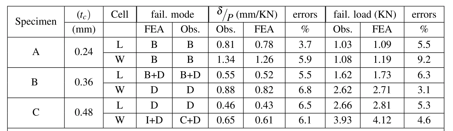
Table 2:A summary of the measurements and FE predictions of the bending rigidity,peak load and failure modes of the folded sandwich beams.
5 Conclusions
The bending response of foldcore composite sandwich beams was investigated experimentally and numerically.The flexural stiffness,strength and failure mechanism of beams at a given topological geometry depended on the core cellorientation and density.The bending stiffness and strength of the sandwich beam increased with the core wall thickness.For thin-walled core,the beam showed softening behavior with core buckling,while for thick-walled cores,the beam displayed stiffened response with core bending and interfacial debonding.Numerically calculation agreed extremely well with experimental results.With selected core geometry,bending isotropy was observed in this study.Future work would focus on the influence of fiber ply-up on the structural bending performance.
Acknowledgement: This work was financially supported by the National Natural Science Foundation of China(Grant Nos.11272103 and 11472091)and the Fundamental Research Funds for the Central Universities(Project No.CDJZR1432 5501).
Allen,H.(1969):Analysis and design of structural sandwich panels.Pergamon Press,Oxford.
Ashby,M.F.(2010):Materials selection in mechanical design.A Butterworth–Heinemann,Boston.
Basily,B.B.;Elsayed,E.A.(2005):Design and development of lightweight sandwich structures with innovative sheet foldcores.Working papers,Department of Industrial and Systems Engineering,Rutgers University.
Belouettar,S.;Abbadi,A.;Azari,Z.;Belouettar,R.;Freres,P.(2009):Experimental investigation of static and fatigue behaviour of composites honeycomb materials using four point bending tests.Compos.Struct.,vol.87,no.3,pp.265–273.
Camanho,P.P.;Dávila,C.G.(2002):Mixed-mode decohesion finite elements for the simulation of delamination in composite materials.NASA-Technical paper,211737,no.1,33.
Finnegan,K.;Kooistra,G.;Wadley,H.N.G.;Deshpande,V.S.(2007):The compressive response of carbon fiber composite pyramidal truss sandwich cores.INT.J.MATER.RES.,vol.98,no.12,pp.1264–1272.
Fischer,S.;Drechsler,K.;Kilchert,S.;Johnson,A.(2009):Mechanical tests for foldcore base material properties.Compos.Part A-Appl.S.,vol.40,no.12,pp.1941–1952.
Heimbs,S.;Cichosz,J.;Klaus,M.;Kilchert,S.;Johnson,A.F.(2010):Sandwich structures with textile-reinforced composite foldcores under impact loads.Compos.Struct.,vol.92,no.6,pp.1485–1497.
Jin,F.;Chen,H.;Zhao,L.;Cai,C.;Kuang,N.(2013):Failure mechanisms of sandwich composites with orthotropic integrated woven corrugated cores:experiments.Compos.Struct.,vol.98,pp.53–58.
Kintscher,M.;Kärger,L.;Wetzel,A.;Hartung,D.(2007):Stiffness and failure behaviour of folded sandwich cores under combined transverse shear and compression.Compos.Part A-Appl.S.,vol.38,no.5,pp.1288–1295.
Klaus,M.;Reimerdes,H.G.(2009):Residual strength simulations of sandwich panels after impact,17th international conference on composite materials(ICCM-17),Edinburgh.
Lebée,A.;Sab,K.(2010):Transverse shear stiffness of a chevron foldcore used in sandwich construction.Int.J.Solids Struct.,vol.47,no.18,pp.2620–2629.
Steeves,C.A.;Fleck,N.A.(2004):Collapse mechanisms of sandwich beams with composite faces and a foam core,loaded in three-point bending.Part I:analytical models and minimum weight design.Int.J.Mech.Sci.,vol.46,no.4,pp.561–583.
Sturm,R.;Klett,Y.;Kindervater,Ch.;Voggenreiter,H.(2014):Failure of CFRP airframe sandwich panels under crash-relevant loading conditions.Compos.Struct.,vol.112,pp.11–21.
Vinson,J.R.(1999):The behavior of sandwich structures of isotropic and composite materials.CRC Press.
Zakirov,I.M.;Alekseev,K.A.(2010):Design of a wedge-shaped folded structure.Journal of Machinery Manufacture and Reliability,vol.39,no.5,pp.412–417.
Zenkert,D.(1995):An introduction to sandwich construction. Engineering Materials Advisory Services,Sheffield,UK.
1Center for Composite Materials,Harbin Institute of Technology,Harbin,China.
2Corresponding author.E-mail:sunyg@hit.edu.cn
3Chongqing Key Laboratory of Heterogeneous Material Mechanics,Chongqing University,Chongqing China.wxz@cqu.edu.cn
 Computers Materials&Continua2015年7期
- Computers Materials&Continua的其它文章
- Investigation on a Two-dimensional Generalized Thermal Shock Problem with Temperature-dependent Properties
- A Macro Element Method to Improve Computational Efficiency in Large-scaled Nonlinear Analysis
- A New Theory of Strain Hardening and its Consequences for Yield Stress and Failure Stress