Subregion graph: A path planning acceleration structure for characterswith variousmotion typesin very large environments
Nicholas Mario Wardhana(),Henry Johan,and Hock Soon Seah
©The Author(s)2015.This article is published with open access at Springerlink.com
Subregion graph: A path planning acceleration structure for characterswith variousmotion typesin very large environments
Nicholas Mario Wardhana1,2(),Henry Johan3,and Hock Soon Seah1,2
©The Author(s)2015.This article is published with open access at Springerlink.com
Modern computer graphics applications commonly feature very large virtual environments and diverse characters which perform different kinds of motions.To accelerate path planning in such a scenario,we propose the subregion graph data structure.It consists of subregions,which are clusters of locally connected waypoints inside a region,as well as subregion connectivities.We also present a fast algorithm to automatically generate a subregion graph from an enhanced waypoint graph map representation, which also supports various motion types and can be created from large virtual environments.Nevertheless, a subregion graph can be generated from any graphbased map representation.Our experiments show that a subregion graph is very compact relative to the input waypoint graph.By firstly planning a subregion path,and then limiting waypoint-level planning to this subregion path,over 8 times average speedup can be achieved,while average length ratios remain as low as 102.5%.
path planning acceleration; very large environments; motion types; abstraction
1 Introduction
Very large virtualenvironments have gained attention from various Computer Graphics(CG) communities since the turn of this century.Various open world games,such as Grand Theft Auto III (GTA III) [1], Just Cause II [2], and TheElderScrollsV:Skyrim [3]featurevery large environments.Some research has also been published[4,5]on crowd simulation in very large environments,indicating the increasing importance of such environments in CG applications.The use of these environments imposes various challenges in CG applications,such as how to efficiently model the environment,how to render the environment while maintaining interactive frame rate,and how to perform path planning in a timely manner.
Characters in CG applications may move differently.Humans and cars can only move on a nearly up-facing,horizontal surface.On the other hand,spiders and lizards have wider movement capabilities,as they can move on a surface of any orientation,such as walls and ceilings.Finally,there are animals like birds and fish whose movements are not restricted to any surface,and are only primarily constrained by their inability to penetrate a surface.A path planning system therefore needs to be aware of diversity in character movements.
Our research focuses on path planning involving various motion types in very large environments.Because of the lack of connectivity information between polygonal 3D objects in these environments,solving path planning problems usually involves creating a graph-based structure called a map representation to approximatethevirtualenvironment.Somecommon map representations include the waypoint graph and navigation mesh.A waypoint graph,also known as a roadmap,contains waypoints,which describe important features in the environment such as corners and openings,and waypoint connectivities.A navigation mesh,on the other hand,approximates walkable surfaces with interconnected triangles or convex polygons.
Recently,Wardhana etal.[6]proposed the enhanced waypoint graph,which supports various motion types and can be automatically generated given a very large virtual environment.We briefly introduce this structure in Section 3.It addresses the issue of large environments by generating local waypoint graphs which are connected into the final waypoint graph.Unlike a navigation mesh,the use of a waypoint graph makes it possible for characters to perform“free-flying”motion which is not restricted to a surface.Edgesarelabelled with motion type,and only edges that support the character’s motion type are traversed during path planning.In spite of its benefits,this mechanism makes use of A*[7]directly on the very large generated waypoint graph.It is consequently impractical,as the interactivity of the application is reduced.
In Section 4,we present the subregion graph,a path planning acceleration structure that consists of subregions, which are clusters of locally connected waypoints inside one region,and subregion connectivities.By planning a subregion path between two points,only waypoints inside the subregion path need be considered,thus reducing the number of visited waypoints and consequently accelerating path planning.In Section 5,we present an algorithm to automatically generate the subregion graph from an enhanced waypoint graph,taking into account the motion types.We also show in Section 5.3 that our algorithm works for any kind of graph-based map representation.A two-step path planning algorithm which uses the subregion graph for path planning is presented in Section 6.
In Section 7,we report the outcomes of some experimentsto evaluate performance and the results of both our generation and path planning algorithms.These experiments show that while a subregion graph needs little space relative to the input waypoint graph,it has the capability to accelerate path planning for characters with various motion types in very large virtual environments.
Our contributions can be summarised as follows.
·An extension to the enhanced waypoint graph which adds support for adhesive motion.
·The subregion graph,a compact data structure to accelerate path planning for various motion types in very large virtual environments.
·A fast method to automatically generate a subregion graph,given an enhanced waypoint graph and a set of motion types.
·A method to generate a subregion graph from any graph-based map representation.
2 Related work
A number of abstraction-based techniques have been proposed to accelerate path planning on large graphs.In this section,we categorise these techniquesinto node-centred,subdivision-based, and node/edge-importance-based.Non-abstractionbased algorithms are also briefly discussed here.Our technique primarily differs from these techniques in its support for different motion types.In addition, our technique generates smaller graphs in shorter time.More detailed comparisons can be found in Section 7.3.
2.1 Node-centred abstraction
This class of abstraction techniques selects some nodes from the graph,then expands from those nodes by following certain rules to create abstractions.Holt¨e etal.[8]proposed STAR abstraction,which groups vertices within a certain distance from a particular vertex into a single abstraction.To refine abstract paths,an alternating search direction(AltO)technique is used,which creates a tree rooted at the goal abstraction to the level equal to the starting abstraction’s,then backtracks from the starting abstraction to the goal only by climbing back up the tree.
Sturtevant and Buro[9]presented a pathfinding technique called Partial-Refinement A*(PRA*).In this work,the abstraction is multi-level and cliquebased,as it is done by grouping at most four vertices into one node at a higher hierarchy level, and repeating this process until further abstraction is impossible.The pathfinding algorithm starts from the immediate common parent of the startingand goal vertices,and partially refines the path byrunningA*between verticesin thelower hierarchy level,truncating the path with every refinement.Bulitko et al.[10]combined abstraction with an ability to learn and improve heuristics in path refinement learning real-time search(PR LRTS), using the same abstraction structure as in PRA*.
2.2 Subdivision-based abstraction
In this category,some constraints are explicitly determined to subdivide the original graph and separate the abstractions.Various structures provide constraints.In the multiway separator approach[11, 12],theconstraintsare pre-selected boundary nodes.Shortest paths between every pair of boundary nodes are recorded,so that only further refinements need be done during the path planning step.
Geometric containers[13]and arc-flag[14-16] use an overlaid 2D grid on the input graph to limit subdivision,and when planning a path to a vertex,only edges marked with the region containing that vertex are considered.The former technique associates every edge to the cell(referred to as a container)that contains nodes,whose shortest paths from one end of the edge to these nodes start with this edge.The latter marks whether an edge is in any shortest path to a region in the grid.Using similar mechanisms,the grid-exclusive Annotated Hierarchical A*(AHA*)method[17]uses boundary cells(called entrances)on the higher-level grid as subdivision constraints.
Mould and Horsch’s HTAP[18]is a hierarchical structure constructed by selecting one node from a region to be brought to the upper level,identifying the nodes to belong to this upper level node using Voronoi cells,and connecting inter-level edges.A path can be found by performing A*on a higher hierarchical level,and the resulting path is used as a guide for lower level path planning.
2.3 Node/edge-importance-based
This class of technique modifies Dijkstra’s or the A* algorithm by filtering thenodesoredges it considers depending on their importance with respect to shortest paths between every pair of nodes.To prune node traversal,Gutman[19]used the concept of reach of a vertex,which is high if the vertex is in shortest paths that are long,and low otherwise.During the node expansion step,only vertices with high reach values are expanded.By adding shortcut edges between nodes with high reach values,better acceleration can be achieved[20].
Sanders and Schultes[21]presented a highway hierarchies technique,based on the premise that outside a certain radius from the starting and goal nodes,only highways or important edges need to be considered.The structure is hierarchical,and paths can be refined to a lower level,by considering the edges that are less important at a higher level.
2.4 Other noteworthy algorithms
One example ofthe non-abstraction class of acceleration techniques is based on look-up table preprocessing.Included in thiscategory are techniques such as the Floyd-Warshall algorithm[22,23],A*-Landmark-Triangle-inequality (ALT) [24], and True-Distance Heuristics (TDH)[25].In the preprocessing step,these techniques create information tables to be used as guidance in either directly determining paths,or as heuristic values,thus reducing computation during the actual path planning step.
3 Review of the enhanced waypoint graph and our extension
Letawaypointgraphbedefined asGW=〈VW,EW〉,where VWis a set of waypoint vertices (or simply waypoints),and EWis a set of undirected edges.The graph is embedded in 3D space,so every waypoint can be represented as a 3D point.An edge which connects two waypoints v1and v2is represented as〈v1,v2〉.A path P is a set of waypoints {v1,v2,···,v|P|},such that for 1≤ i≤ |P|-1,〈vi,vi+1〉∈EW.We impose the constraint that there are no duplicate waypoints in P.The length of a path P is equal to the sum of the distances between successive waypoints in P.
The enhanced waypoint graph generation algorithm makes use of a 3D uniform grid containing congruent axis-aligned boxes called regions in order to process very large environments.If a waypoint is located inside only one region,it is a local waypoint; if it is located at the shared boundary between two regions,it is a boundary waypoint.The set region(v) contains all regions which contain waypoint v.
Every edge in an enhanced waypoint graph is labelled with a motion type.During path planning, only edges that support the character’s movement are traversed.Wardhana et al.’s paper defines two motion types,forsurfaceand volumetric motions.They respectively correspond to movement on ground-like surfaces and free-flying movements in 3D.Each character may support multiple motion types.For example,while a car can only perform surface motion,a bird can perform both surface and volumetric motions.
Our extension:In this paper,we add another motion type called adhesive motion.It still is performed on a surface,but the surface can be of any orientation,excluding almost horizontal surfaces.An edge is labelled with adhesive motion if it is entirely located near a surface whose normal neither points upward nor nearly upward.Animals like spiders and lizards are examples of characters that can perform adhesive motion.Figure 1 illustrates the various motion types.
In graphicsapplications,pathsare planned between two arbitrary points.Wardhana et al.[6] proposed different traversability tests for surface and volumetric motions,to find whether a character at an arbitrary point can move to a particular waypoint.Here,we introduce a traversability test for adhesive motion.Let l be a line connecting the character’s position and a waypoint.The line l is sampled at an interval of the character’s radius, and for every sample point,we compute a vector to the nearest polygon.If all vectors from these sample points are not too different(tested using dot product),the character can perform adhesive motion to the waypoint.
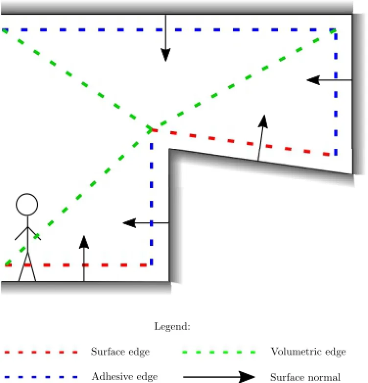
Fig.1 Edges that support different motion types.
4 The subregion graph and terminology
The idea behind our subregion graph,as depicted in Fig.2,is to cluster waypoints in every region of the enhanced waypoint graph based on their connectivity,and to represent them as a single abstraction node.Given a motion type set MC⊆M,where M is the set of all motion types(here, M ≡ {surface,adhesive,volumetric}),a group of waypoints in one abstraction must be visitable from each other without going to another abstraction by only considering edges that support any motion m∈MC.One region may contain multiple disconnected waypoint sets,so it can have multiple subregions.A subregion graph also describestheconnections between these abstractions,and can be used to filter the waypoints so a limited number of waypoints is visited during path planning,thus accelerating the process.
Subregion graphs are constructed for every motion type set in the application.If the application supports n motion types,at maximum we need 2n-1 subregion graphs to be generated for each possible combination of motion types.However,since some characters share similar motion type sets,fewer than 2n-1 subregion graphs are typically needed.
We now introduce some terminology,illustrated by the enhanced waypoint graph input example in Fig.2(a).It has 14 waypoints v1,v2,···,v14,and 15 edges which support either surface or adhesive motion types.Let us also define two motion type sets M1={surface}and M2={surface,adhesive}.In the same figure,the rectangles separated by grey lines represent regions r1,r2,r3,and r4.
Definition 1.A waypoint vsis locally visitable from another waypoint vgwith respect to a motion type set MC⊆ M and region r if there exists a path P={vs,···,vg}such that for every v∈P, r∈region(v),and for 1≤i≤|P|-1,the motion type m(〈vi,vi+1〉)is in MC.
In Fig.2,with respect to motion type set M1, within region r1,waypoint v3is locally visitable
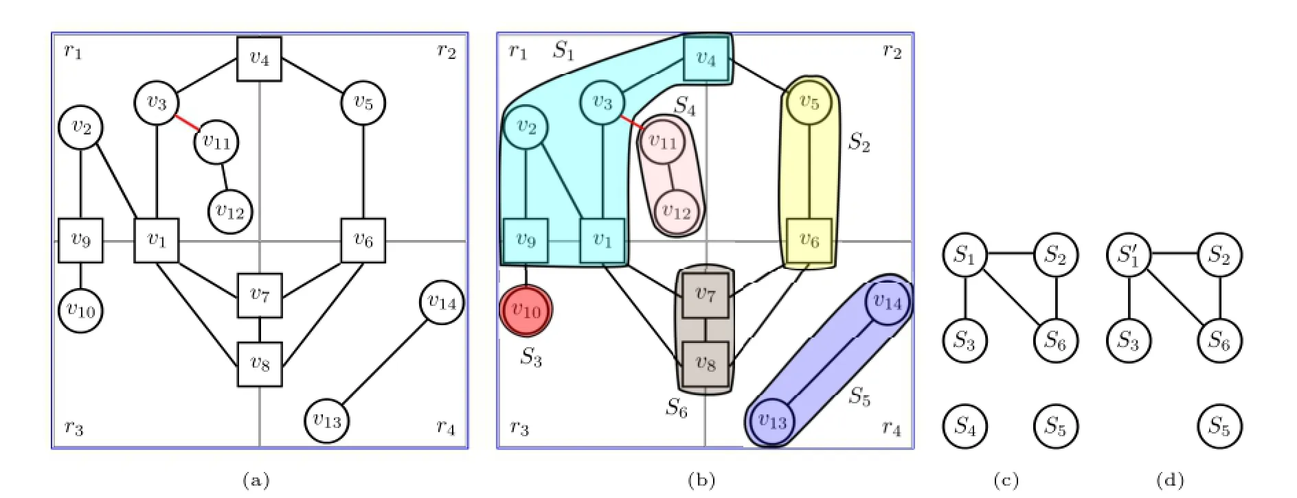
Fig.2 (a)An example of a 2D enhanced waypoint graph,consisting of 4 regions,14 waypoints,15 edges,and 2 motion types.Circles and squares are respectively local and boundary waypoints,while black and red edges respectively represent surface and adhesive motions.(b)The subregions with respect to surface motion only are overlaid with different colours on the waypoints.(c)The subregion graph,again with respect to surface motion only,describes the corresponding subregions with respect to the waypoint graph,and the connection between the subregions.Circles and edges respectively denote subregions and subregion connectivities.(d)A different subregion graph generated with respect to both surface and adhesive motions.Notice that instead of S1,it has S'1=S1∪S4,while the original S4is non-existent.
from waypoints v1,v2,v4,and v9.Waypoints v11and v12are not locally connected to v3since there is an adhesive edge that separates them.On the other hand,with respect to M2,all these waypoints are locally visitable from each other.
Definition 2.A subregion S is a set of waypoints such that any two unique waypoints in S are locally visitable from each other with respect to motion type set MC.Two subregions S1and S2on subregion graph GSare connected if there is an edge〈v,w〉such that waypoint v is in S1,waypoint w is in S2, and motion type m(〈v,w〉)is in MC.
Definition 3.A subregion graph isa graph GS= 〈VS,ES〉whose vertex set VScontains all subregions,and whose edge set ESdescribes the connectivity information linking the subregions with respect to motion type set MC.
Figure 2(b)shows an example of subregions for motion type set M1.To every waypoint v,we associate a label L(v),indicating the subregion which contains v.The corresponding subregion graph is shown in Fig.2(c),while another subregion graph for motion type set M2is visualised in Fig.2(d).Note that these subregion graphs have differentnumbersofsubregions.Waypointsv3and v11are connected by an adhesive edge,so they belong to subregions S1and S4respectively in Fig.2(c),but are both in subregionin Fig.2(d).
Definition 4.A subregion path PSis a set of subregions,such that for 1≤i≤|PS|-1,it follows thatWe require there are no duplicate subregions in PS.
A subregion graph guarantees a 100%success rate for path planning.In other words,planning a path between the same pair of waypoints without and with subregion graphs will either in both cases return a path,or in both cases,not return a path.We prove this property in Theorems 1 and 2.
Theorem 1.Ifthereisapathbetweentwo waypoints vsand vg,there is also a subregion path in subregion graph GSwhich connects a subregion in L(vs)and L(vg).
Proof Given a path P={v1,v2,···,v|P|},we can construct a list of subregions PS=L(v1)∪L(v2)∪···∪L(v|P|)on subregion graph GS.Since every successive pair of waypoints is connected, their respective subregions are by definition also connected.We can then remove any duplicate subregions from PS,and the result is a subregion path consisting of unique subregions,each connected to the next. ■
Theorem 2.If there is a subregion path between two subregions Ssand Sg,there is also a pathbetween every two waypoints vs∈Ssand vg∈Sg.
Proof Let PSbe a subregion path consisting of{S1,S2,···,S|PS|},where S1=Ssand S|PS|= Sg.By the definition of a subregion,there must be at least one edge which connects a waypoint in S1to another waypoint in S2,and all other waypoints in both subregions are connected to these waypoints.Using the same definition,waypoints in S2are also connected to waypoints in S3.Since waypoints in S1are connected to waypoints in S2and waypoints in S2are connected to waypoints in S3,waypoints in S1are also connected to S3.This proof is extended by induction until S|PS|,creating a path which connects waypoints in S1with those in S|PS|. ■
5 Automatic generation of subregion graph
Our algorithm to automatically generate a subregion graph,as given in Algorithms 1,2,and 3,takes two input data items,namely an enhanced waypoint graph GWand a character’s motion type set MC⊆M.The algorithm returns the following two data structures:
·a subregion graph GS,which consists of a subregion set VSand a subregion connectivity set ES;
·for every waypoint v,a label L(v),which is the subregion containing the waypoint.
Alllabelsareinitialised asNULL,in which condition waypoint v is unlabeled.
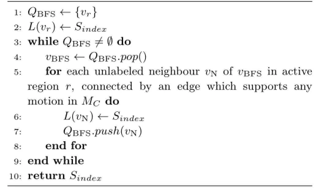
To generate these data,Algorithm 1 uses an index variable,which is the index of the next subregion to be inserted into VS.This variable is initialised to 1,and is incremented after every subregion insertion.The algorithm consists of two steps,namely subregion detection and subregion connection,which are explained in Sections 5.1 and 5.2.
5.1 Subregion detection
Recall from Definition 2 that a subregion contains waypoints which are locally visitable from each other.Therefore,we can detect a subregion by performing Breadth First Search(BFS)algorithm to visit a set of inteconnected waypoints from a starting waypoint without going out of the region containingthem.In Algorithm 2,the subregion detection step is done by iterating through the list of unlabeled waypoints to find a starting waypoint vrfrom which we start detection.The starting waypoint must beincident to at least one edge which supports a motion type in MC,so that a character at that waypoint can visit the neighbouring waypoint.
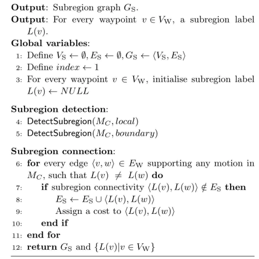
Algorithm 1:GenerateSubregionGraph(GW,MC)
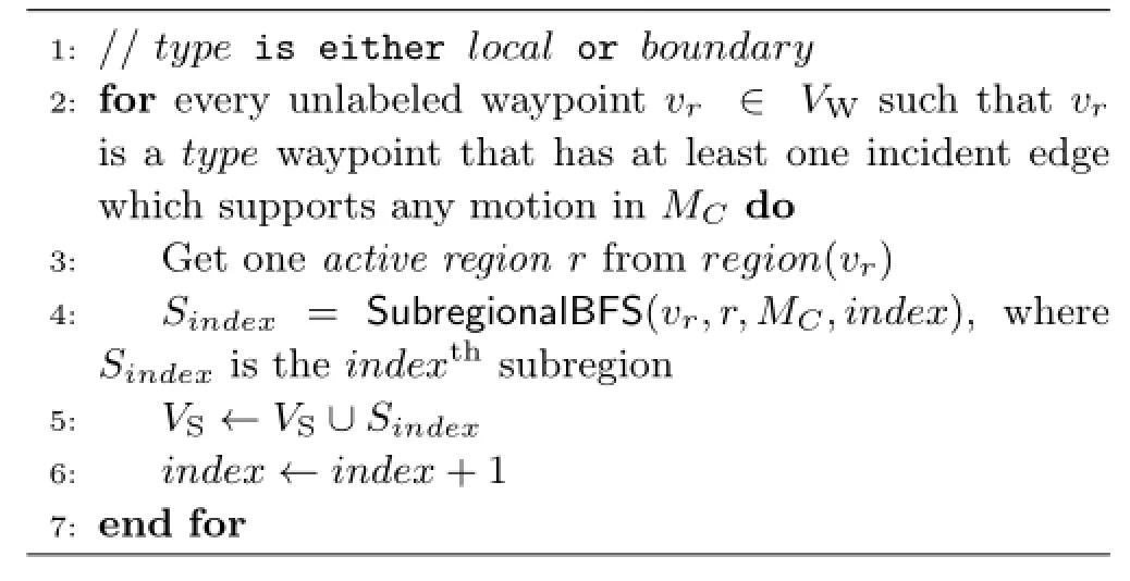
Algorithm 2: DetectSubregion(MC,type)
Algorithm 3:SubregionalBFS(vr,r,MC,index)
In Algorithm 1,subregion detection from local waypointsand from boundary waypointsare separate.We prioritise local waypoints because it is clear that local waypoints are only contained in one region.Nevertheless,some boundary waypoints are also labeled in this process.
Subregion detection is constrained to a region called the active region.If the starting waypoint is a local waypoint,it is contained in only one region, which is used as the active region.On the other hand, a boundary waypoint borders two regions,so the active region is selected randomly.
The rest of the step,shown in Algorithm 3, is similar to regular BFS.The only modifications arethatthewaypointstobeexpanded must also be unlabeled,inside the active region,and connected to an edge that supports a motion type in MC.The newly detected subregion Sindex(the indexthsubregion)is then added to VS,and index is incremented.This process is repeated for every newly detected subregion.
It should be noted that depending on the order of processing the waypoints,different subregion graphs may be obtained.Therefore,we consider an experiment to see how different waypoint processing orderaffectsthe resulting subregion graph in Section 7.1.
5.2 Subregion connection
After detecting all subregions,we are left with the task of connecting them.To do so,the algorithm visits every edge which supports any motion in MC,and checks the two waypoints v and w at its end,examining their respective labels L(v)and L(w).If they are different and not yet connected,a connection is established.
To assign costs to subregion connections,we considered the following schemes.We performed tests,reported in Section 7.2,to find which schemes lead to fastest path planning,and which return paths that deviate less in terms of path length,compared to the path constructed without using a subregion graph.
·Fixed Cost(FC).Every subregion connectivity has a fixed cost with value 1.
·Minimum Length(MinL).Everysubregion connectivity is given a cost equal to the length of the shortest edge which connects two waypoints in both subregions.
·Average Length(AvgL).Similar to MinL,but the average length of all edges connecting two waypoints in both subregions is used.
·Maximum Length(MaxL).Similar to MinL,but the length of the longest edge is used.
·Centroid Distance(CD).The cost of every subregion connection is set to the distance between the centroids of two subregions.A subregion’s centroid is defined to be the average location of the waypoints within it.
5.3 Generation algorithm for other graphbased map representations
The aforementioned subregion graph generation algorithm uses an enhanced waypoint graph as input, which comes with a regional subdivision structure.If the input waypoint graph is generated using another technique,this structure may be missing.As a workaround,we only need to compute the axisaligned bounding box of the waypoint graph,and subdivide it into Rx×Ry×Rzregions.Then,every waypoint is associated with one or two regions, depending on its position relative to the subdivision, and we can continue with Algorithm 1.
A subregion graph can also be created for a navigation mesh by firstly contructing the dual graph from the navigation mesh.Every node in this dual graph is set to the centre of the corresponding polygon.This dual graph can then be treated as an input,and the step in the previous paragraph can be applied.However,it should be noted that in spite of recent developments in multi-layered environment[26,27],a navigation mesh can only handle surface motion.
6 Path planning using the subregion graph
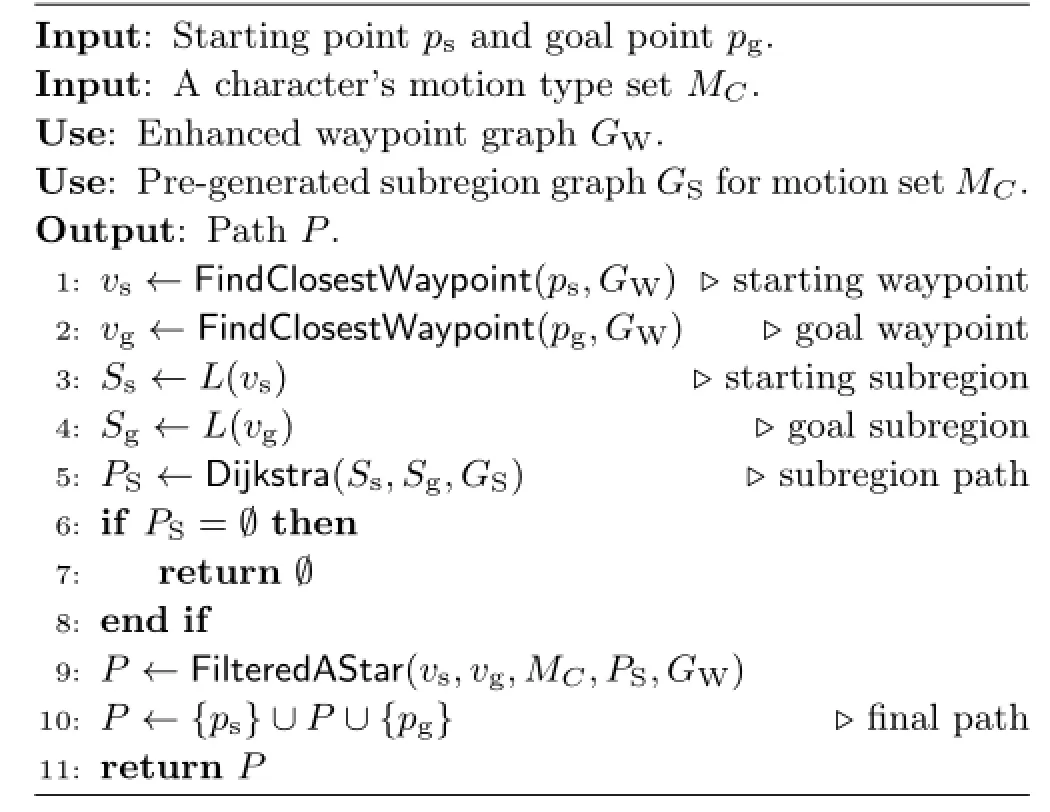
Algorithm 4 summarises our path planning algorithm using a subregion graph.To accelerate path planning,it is done on two levels,namely at the subregion graph level,and then at the waypoint graph level to return the final path.Using an illustration in Fig.2,suppose a character with motion type set M2is moving from v3to v10.Without a subregion graph,all waypoints will be considered.With the subregion graph inFig.2(d),we can find a subregion pathand only consider waypoints in those subregions,thus considering fewer waypoints.
The path planning algorithm takes as input a starting point ps,a goal point pg,an enhanced waypoint graph GW,and a subregion graph GS.We use the subregion graph which supports the same motion type set MCas the querying character.The path planning process begins by looking for vsand vg,which are the closest waypoints from psand pg.We firstly perform nearest neighbour search over the waypoints which are incident to an edge which supports a motion in MC,and check every waypoint in order of proximity.If a line between the starting point PSand the waypoint is not obstructed,and the character can move along the line(the motion type identification method in Section 3 is used),the waypoint is selected as vs.The same mechanism is used to determine vg.
Algorithm 4:PlanPathWithSubregionGraph(ps,pg,MC)
After finding the closest traversable waypoints,we look for the starting subregion Ssand goal subregion Sgby respectively checking the labels of waypoints vsand vgwith respect to subregion graph GS.This subregion information is used to find the shortest subregion path PSusing Dijkstra’s algorithm[28] on GS.Dijkstra’s algorithm is used since most cost schemes presented in Section 5.2,except the CD scheme,lack the heuristic formulae required by A*.
If the subregion path PSis empty,there is no path between the two points,and the algorithm stops here.Otherwise,we can determine the final path P using a filtered A*algorithm,which only expands waypoints inside any subregion in the subregion path PS,thus narrowing down the number of checked waypoints.The result of this process is a path P.The algorithm finally appends points psand pg, respectively at the beginning and the end of the path P,and returns it.This path can be further smoothed in a post-processing step,for example using a technique akin to Pinter’s algorithm[29].
7 Experimental results
To evaluate our subregion graph generation and path planning algorithms,we performed two types of experiments.In Section 7.1,we show the result of an experiment to see the effect of waypoint processing order on the generated subregion graph’s size.In Section 7.2,we calculate the success rate, acceleration,and quality of path planning without and with subregion graphs,using different cost schemes as given in Section 5.2.These experiments were done on a workstation with an Intel Xeon E5-1650 3.20 GHz processor and 16 GB of memory.We use the graph data structure,Dijkstra’s algorithm, and filtered A*search implementations in the Boost Graph Library[30].The Ogre3D library[31]was used as the rendering engine.Section 7.3 presents comparisons between our approach and existing techniques.
We used two virtualenvironments,namely Kampong Glam and Marina Bay,shown in Figs.3(a) and 3(b)respectively,which are two areas in Singapore.The former has an area of 488.65m× 510.9m,with 79,875 triangles,a maximum altitude of 80.29 m,10×2×11 regions,and a waypoint graph consisting of 41,365 waypoints and 1,474,971 edges.The latter has an area of 2338.9m×2832.48m, with 555,238 triangles,a maximum altitude of 273.26 m,47×6×57 regions,and a waypoint graph consisting of 1,152,979 waypoints and 57,281,715 edges.
7.1 Effect of waypoint processing order on generated subregion graph size
In this experiment,we generated subregion graphs 100 times for both Kampong Glam and Marina Bay scenes with various motion type sets,and recorded the numbers of subregions and subregion connectivites in each case.Table 1 shows the statistical data recorded and calculated in theexperiment.To evaluate the result,we use relative standard deviation(RSD)which describes the data spread,expressed as a fraction of the average.RSD is the percentage form of coefficient of variation,given by RSD=SD/mean×100%,where SD and mean are respectively the standard deviation and the average of either the numbers of subregions or numbers of subregion connectivities.We calculated RSDs of the numbers of subregions as well as the numbers of the subregion connectivities,and found that the values are at maximum only 2.12%for the subregions, and 1.75%for the subregion connectivities.We can therefore consider the data as quite tight.This is caused by the fact that subregions are detected inside one region,so the resulting subregions will not be too different,even when generated with a different order of waypoints.

Table 1 The minimum,average,and maximum subregion graph sizes after 100 times of generations in Kampong Glam and Marina Bay environments with respect to different motion types.Motion types are S=Surface;A=Adhesive;V=Volumetric.RSD= Relative Standard Deviation

Fig.3 Virtual environments used in our experiments:(a)Kampong Glam and(b)Marina Bay.
7.2 Path planning using subregion graphs with different cost functions
These experiments involved sampling waypoints from the waypoint graph,and performing path planning repeatedly for every pair of waypoints without using a subregion graph(No SG)and with a subregion graph,taking into account the cost schemes presented in Section 5.2.To sample the waypoints,we created groups containing k×k× k regions(any remaining regions are grouped as necessary).From each group,we randomly picked one waypoint with at least one incident edge supporting a motion type in the character’s motion type set.Path planning was then done for all pairs of sampled waypoints.Some examples of path planning results with and without a subregion graph can be seen in the accompanying video available in the Electronic Supplementary Material of this article.
Table 2 shows the statistics for the Marina Bay scene with 6×6×6 group size for a character which can move only on surface and volumetric edges(the results for other motion type sets can be seen in the ElectronicSupplementaryMaterial).Withtheseconfigurations,the number of waypoint pairs was 3160,out of which 2158 returned paths.In this table,a case was successful if path planning without and with a subregion graph either both returned a path,or both failed to return a path.We found that the cases for all pairs of sampled waypoints were successful,and hence the success rates were 100% for every setting.

Table 2 Statistics for surface and volumetric path planning using subregion graph with different costs for Marina Bay
To evaluate the cost schemes,we used two measurements,namely average length ratio and average speedup.Given n pairs of waypoints such that a path exists between the two waypoints,letdefine the path between the ithwaypoint pair for a particular cost scheme C,with i={1,2,···,n},andbe the path planned without using a subregion graph.Likewise,letandhave similar definitions for the computation times for path planning.The average length ratio¯L compares one cost scheme with path planning without a subregion graph in terms of the resulting path lengths,whereas the average speedup¯S explains how much acceleration was achieved on average for a particular cost scheme.These can be formulated as

These experiments and calculations show that path planning using a subregion graph with any cost scheme,except Minimum Length,results in paths that are not significantly longer than paths planned without a subregion graph,as their average length ratios are close to 100%.The CD scheme had the lowest average length ratios for all scenes and motion type sets we experimented with.This phenomenon was caused by the CD scheme’s resemblance to the actual distances between waypoints in different subregions.
The key to accelerating path planning lies in restricting graph traversal to the subregion path, as visualised in the example in Fig.4.In most cases where paths are found,the subregion graph with Fixed Cost scheme has the highest average speedup for all configurations.This is because this cost scheme returns the fewest number of subregions, which means fewer waypoints are visited in path planning.Consequently,this cost scheme has the least processing time.
Table 3 summarises the statistics of this experiment with respect to the FC scheme, asan example costscheme.In both virtual environments,surface and adhesive motions have lower speedups than the cases where volumetric motion is possible.Surface and adhesive motions are in this sense more restrictive compared to volumetric motion,because characters that support volumetric motion type have more possible paths.Nevertheless, we did not observe significant difference in the average length ratios.Ifpaths do notexist, depending on the motion type sets,higher speedupsof over 200 times can be achieved regardless of the cost scheme,since path planning stops at subregion level.

Fig.4 (a)Without a subregion graph,120,878 edges were traversed(red lines)when planning a path between two distant waypoints.(b)The same set of edges with the environment hidden.(c)With a subregion graph,the number of traversed edges is reduced to 13,483,leading to faster path planning.(d)The same set of edges with the environment hidden.

Table 3 Statistics of path planning using a subregion graph with fixed cost.S=Surface;A=Adhesive;V=Volumetric
7.3 Comparisons with existing techniques
As mentioned in Section 4,our technique’s main advantage is its capability to support various motion types in 3D.Among the techniques that we reviewed, only Harabor and Botea’s AHA*[17]supports different motion types,which they define in terms of character size and capability to move on different terrain such as ground and trees.Their definition is limited to a 2D grid map.
Our subregion graph generation mechanism takes only around 20 seconds to process a graph with millions of waypoints and tens of millions ofedges.This is much faster than existing data structure generation procedures.For example, Mould and Horsch’s HTAP[18]needs 7.5 minutes to generate an abstraction for a 729×729 grid,whereas Sanders and Schultes’s highway hierarchies[21]need 2-4 hours to generate,given a graph of comparable size(millions or tens of millions of nodes and edges).(However,the authors of these works used older generation CPUs,with respectively 1.8 GHz and 2.2 GHz AMD processors.)
The subregion graph is also compact.For an example presented in Section 7.1,depending on the motion type sets,the number of subregions is not more than 3%of the number of input waypoints, while the number of subregion connections is not more than 0.2%of the number of input edges.As a comparison,Harabor and Botea reported that on a 512×512 grid,their AHA*generated abstraction graph with a size of 2%-18.5%of the input nodes and 0.9%-38.4%of the input edges,depending on the frequency of obstacles.
To check the storage requirements of subregion graphs,we saved them into binary files and checked their sizes.Depending on the motion type set,the sizes of these files range from 16-34KB for the Kampong Glam scene,and 393-2259KB for Marina Bay scene.The only additional data needed are the waypoint labels,which are a mapping between a waypoint and a subregion.For the environments we considered,not more than 216=65536 subregions were generated.Therefore,only two additional bytes are needed per waypoint to keep this label information.This is much more compact than existing structures,including Sadners and Schultes’highway hierarchies and Goldberg et al.’s shortcut technique[20],which need 1.8-3 GB storage for input graphs of comparable size.We also do not need to add extra nodes or edges to the input graph, which are needed by hierarchical structures[9,18] or Goldberg’s shortcut technique.Considering these factors,subregion graphs are thus more suitable for large graphs in applications such as computer games, due to the low memory requirement.
Some of the discussed algorithms [11-16,19,21,24]were specifically designed for road networks.They are common targets for path planning acceleration mechanisms because of their wide use in traffic planning applications and easily available data[32].These techniques can return optimal shortest paths and may achieve thousands of times speedup with respect to path planning withoutacceleration structures.However,road networks are different from our waypoint graphs: they are usually sparse(the number of edges is linearly proportional to the number of nodes),are planar or almost planar(no or very few edges intersect each other when the graph is embedded in a plane),and contain only one connected component (because all cities are connected).The input data for a subregion graph may not have these properties.
8 Conclusions and future work
We have presented the subregion graph,a compact graph-based data structure which can be used to accelerate path planning in very large virtualenvironments involving various motion types without significantly sacrificing path length.A subregion graph acts as an abstraction on top of a waypoint graph,and its primary role is to reduce the number of visited waypoints during path planning.We also presented a fast algorithm to automatically generate a subregion graph,as well as a path planning method using a subregion graph.Our experiments showed thatthesubregion graph generation algorithm does not generate significantly different subregion graph sizes with respect to the waypoint processing order.Depending on the motion type sets,the numbers of subregions and subregion connections are respectively not more than 3%and 0.2%of the size of input waypoint graphs.With a subregion graph,over 8 times acceleration can be achieved,while average path length ratios are maintained to as little as only 102.5%.If no path exists between two points,a speedup of over 200 times can be achieved.
For future work, we willconsider further correlation of subregion graph size with input enhanced waypoint graph size,as well as performing further comparisons with existing techniques.An exact path planning algorithm using a subregion graph,that returns the same path as the one returned without a subregion graph,and using adaptive subdivision(e.g.,an octree[33])to build a subregion graph,are interesting directions to explore.Anotherresearch direction istowards efficient multi-character path planning,for example planning crowd pathsin a very largeurban scene.Finally,due to the fast generation algorithm, we foresee that we can perform real-time updates of a subregion graph in a dynamic environment.
Acknowledgements
Thisresearch wassupported by theNational Research Foundation, Singapore, under its Interactive Digital Media (IDM) Strategic Research Programme.Henry Johan is supported by Fraunhofer IDM@NTU,which is funded by the National Research Foundation(NRF)and managed through the multiagency Interactive&Digital Media Programme Office(IDMPO)hosted by the Media Development Authority of Singapore(MDA).The models of Kampong Glam and Marina Bay were created by MDA,and are used in this research with permission. Open Access This article is distributed under the terms of the Creative Commons Attribution License which permits any use,distribution,and reproduction in any medium,provided the original author(s)and the source are credited.
Electronic Supplementary MaterialSupplementary materials,containing further statistics and chartsof the experimental results for various motion type sets as described in Section 7.2,as well as a video that shows comparisons of path planning results without and with a subregion graph,are available in the online version of this article at http://dx.doi.org/10.1007/s41095-015-0018-0.
[1]Grand Theft Auto III(DVD).Rockstar Games,2001.
[2]Just Cause II (Steam). Eidos Interactive, 2010. Available at http://store.steampowered.com/app/81901.
[3]The Elder Scrolls V: Skyrim (Steam). Bethesda Softworks, 2011. Available at http://store.steampowered.com/app/7282501.
[4]Plaku,E.;Kavraki,L.E.Distributed sampling-based roadmap of trees for large-scale motion planning.In: Proceedings of the 2005 IEEE International Conference on Robotics and Automation,3868-3873,2005.
[5]Samperi,K.;Hawes,N.;Beale,R.Improving map generation in large-scale environments for intelligent virtual agents.In: The AAMAS-2013 Workshop on Cognitive Agents for VirtualEnvironments, 2013.Available at http://www.cs.bham.ac.uk/~nah/ bibtex/papers/samperietal2013cave.pdf.
[6]Wardhana,N.M.;Johan,H.;Seah,H.S.Enhanced waypointgraph forsurfaceand volumetricpath planning in virtual worlds.The Visual Computer Vol. 29,No.10,1051-1062,2013.
[7]Hart,P.E.;Nilsson,N.J.;Raphael,B.A formal basis for the heuristic determination of minimum cost paths.IEEE Transactions on Systems Science and Cybernetics Vol.4,No.2,100-107,1968.
[8]Holt¨e,R.C.;Mkadmi,T.;Zimmer,R.M.;MacDonald, A.J.Speeding up problem solving by abstraction:A graph oriented approach.Artificial Intelligence Vol.85, Nos.1-2,321-361,1996.
[9]Sturtevant,N.;Buro,M.Partial pathfinding using map abstraction and refinement.In:Proceedings of the 20th National Conference on Artificial Intelligence,Vol.3, 1392-1397,2005.
[10]Bulitko,V.;Sturtevant,N.;Lu,J.;Yau,T.Graph abstraction in real-time heuristic search.Journal of Artificial Intelligence Research Vol.30,No.1,51-100, 2007.
[11]Frederickson,G.N.Fast algorithms for shortest paths in planar graphs,with applications.SIAM Journal on Computing Vol.6,No.6,1004-1022,1987.
[12]K¨ohler,E.;M¨ohring,R.H.;Schilling,H.Acceleration ofshortestpath and constrained shortestpath computation.Lecture Notes in Computer Science Vol. 3503,126-138,2005.
[13]Wagner, D.; Willhalm, T.Geometric speedup techniques for finding shortest paths in large sparse graphs.Lecture Notes in Computer Science Vol.2832, 776-787,2003.
[14]Hilger,M.;K¨ohler,E.;M¨ohring,R.H.;Schilling, H.Fast point-to-point shortest path computations with arc-flags.In:The Shortest Path Problem:Ninth DIMACS Implementation Challenge.Demetrescu,C.; Goldberg,A.V.;Johnson,D.S.Eds.American Mathematical Society,41-72,2009.
[15]Lauther,U.An extremelyfast,exactalgorithm for finding shortest paths in static networks with geographical background. In: Geoinformation und Mobilit¨at-von der Forschung zur praktischen Anwendung,Vol.22,219-230,2004.
[16]M¨ohring,R.H.;Schilling,H.;Sch¨utz,B.;Wagner,D.; Willhalm,T.Partitioning graphs to speed up Dijkstra’s algorithm.Lecture Notes in Computer Science Vol. 3503,189-202,2005.
[17]Harabor,D.;Botea,A.Hierarchical path planning for multi-size agents in heterogeneous environments.In: IEEE Symposium on Computational Intelligence and Games,258-265,2008.
[18]Mould,D.;Horsch,M.C.A hierarchical terrain representation for approximately shortest paths. Lecture Notes in Computer Science Vol.3157,104-113, 2004.
[19]Gutman,R.J.Reach-based routing:A new approach to shortest path algorithms optimized forroad networks.In: Proceedings of the 6th Workshop on Algorithm Engineeringand Experimentsand the First Workshop on Analytic Algorithmics and Combinatorics,100-111,2004.
[20]Goldberg,A.V.;Kaplan,H.;Werneck,R.F.Reach for A*:Efficient point-to-point shortest path algorithms. In:Proceedings of the Eighth Workshop on Algorithm Engineering and Experiments,129-143,2006.
[21]Sanders,P.;Schultes,D.Highway hierarchies hasten exact shortest path queries.Lecture Notes in Computer Science Vol.3669,568-579,2005.
[22]Floyd, R.W.Algorithm 97: Shortest path. Communications of the ACM Vol.5,No.6,345,1962.
[23]Warshall,S.A theorem on boolean matrices.Journal of the ACM Vol.9,No.1,11-12,1962.
[24]Goldberg,A.V.;Harrelson,C.Computing the shortest path:A*search meets graph theory.In:Proceedings of the Sixteenth Annual ACM-SIAM Symposium on Discrete Algorithms,156-165,2005.
[25]Felner,A.;Sturtevant,N.;Schaeffer,J.Abstractionbased heuristics with true distance computations.In: Proceedings of the Eighth Symposium on Abstraction, Reformulation,and Approximation,74-81,2009.
[26]Oliva,R.;Pelechano,N.NEOGEN:Near optimal generator of navigation meshes for 3D multi-layered environments.Computers&Graphics Vol.37,No.5, 403-412,2013.
[27]Van Toll,W.G.; CookIV,A.F.; Geraerts, R.Navigation meshes for realistic multi-layered environments.In:IEEE/RSJ International Conference on Intelligent Robots and Systems,3526-3532,2011.
[28]Dijkstra,E.W.A note on two problems in connexion with graphs.Numerische Mathematik Vol.1,No.1, 269-271,1959.
[29]Pinter,M.Toward more realistic pathfinding.2001. Available at http://www.gamasutra.com/features/ 20010314/pinter 01.htm.
[30]Siek,J.;Lee,L.-Q.;Lumsdaine,A.The Boost Graph Library (BGL)(version 1.57).2014.Available at http://www.boost.org/libs/graph/.
[31]The OGRE Team.OGRE—Object-oriented Graphics Rendering Engine(version 1.7.3).2011.Available at http://www.ogre3d.org/.
[32]Wagner,D.; Willhalm,T.Speed-up techniques forshortest-path computations.LectureNotesin Computer Science Vol.4393,23-36,2007.
[33]Garcia,F.M.;Kapadia,M.;Badler,N.I.GPU-based dynamic search on adaptive resolution grids.In: 2014 IEEE International Conference on Robotics and Automation,1631-1638,2014.

Nicholas Mario Wardhana is currently a project officer in the MultiplAtform Game Innovation Centre (MAGIC), Nanyang Technological University(NTU),Singapore,as well as a doctoral student in the School of Computer Engineering,NTU.He previously received a Sarjana Teknik degree in electrical engineering from Universitas Gadjah Mada(UGM),Yogyakarta,Indonesia,in 2007.His research interests include motion planning,computer graphics,and geometric computing.

Henry Johan is a senior research fellow in Fraunhofer IDM@NTU (Singapore).Previously he was a postdoctoral fellow in the Department of Complexity Science and Engineering at the University of Tokyo(Japan).Then, hejoined theSchoolofComputer Engineering at Nanyang Technological University (Singapore)asan assistantprofessor.His research interests in computer graphics include rendering, animation,and shape retrieval.He received his B.S.,M.S., and Ph.D.degrees in computer science from the University of Tokyo in 1999,2001,and 2004,respectively.

Hock Soon Seah is a professor at the School of Computer Engineering(SCE) at Nanyang Technological University (NTU),Singapore.He directs the National Research Foundation MultiplAtform Game Innovation Centre (MAGIC),which is supported by the Singapore Media Development Authority,to champion efforts in research,development, education,commercialization,and impact of digital games in Singapore.He is a Fellow of the Singapore Academy of Engineering.
Other papers from this open access journal are available free of charge from http://www.springer.com/journal/41095. To submit a manuscript,please go to https://www. editorialmanager.com/cvmj.
1Multi-plAtformGame InnovationCentre(MAGIC), Nanyang Technological University,XFrontiers Block, 02-M1 Research Techno Plaza,50 Nanyang Drive, Singapore,637553. E-mail: mario.wardhana@ntu. edu.sg(),ashsseah@ntu.edu.sg.
2School of Computer Engineering,Nanyang Technological University,Block N4 #02a-32,Nanyang Avenue, Singapore,639798.
3Fraunhofer IDM@NTU, Nanyang Technological University, NS1-1 Level5, 50 Nanyang Avenue, Singapore,639798.E-mail:henryjohan@ntu.edu.sg.
Manuscript received:2015-08-16;accepted:2015-08-29
 Computational Visual Media2015年2期
- Computational Visual Media的其它文章
- A simple approach for bubble modelling from multiphase fluid simulation
- Local pixel patterns
- Image recoloring using geodesic distance based color harmonization
- Semantic movie summarization based on string of IE-RoleNets
- A retargeting method for stereoscopic 3D video
- Cross-depiction problem: Recognition and synthesis of photographs and artwork
