Time domain simulations of radiation and diffraction by a Rankine panel method*
ZHANG Wei (张伟), ZOU Zaojian (邹早建),2
1. School of Naval Architecture, Ocean and Civil Engineering, Shanghai Jiao Tong University, Shanghai 200240,China, E-mail: drwood@sjtu.edu.cn
2. State Key Laboratory of Ocean Engineering, Shanghai Jiao Tong University, Shanghai 200240, China
Time domain simulations of radiation and diffraction by a Rankine panel method*
ZHANG Wei (张伟)1, ZOU Zaojian (邹早建)1,2
1. School of Naval Architecture, Ocean and Civil Engineering, Shanghai Jiao Tong University, Shanghai 200240,China, E-mail: drwood@sjtu.edu.cn
2. State Key Laboratory of Ocean Engineering, Shanghai Jiao Tong University, Shanghai 200240, China
The radiation and the diffraction of a ship with a forward speed are studied by using a time domain Rankine panel method. The free surface conditions are linearized onto an undisturbed free surface based on the double body flow. The linearized body boundary condition is applied on the mean wetted hull surface. The fluid domain boundary is discretized by a collection of quadric panels. The unknown quantities, including the free surface elevation, the normal flux over the free surface and the potential on the fluid domain boundary, are determined at each time step. The numerical results are compared with experimental data and other numerical solutions, showing satisfactory agreements.
radiation, diffraction, Rankine source, panel method, time domain analysis
Introduction0F
In the past two decades, the three-dimensional panel method combined with the time domain analysis techniques finds increasingly wider applications in simulating the free surface flow around a ship. Based on the choices of the elementary singularity, there are two general categories of the time domain panel methods for the ship hydrodynamics studies.
The first category employs the transient Green function. The methods of this category have the advantages of the free surface integration being avoided and the radiation condition satisfied automatically. But the integration of the transient Green function is made difficult, especially when the ship is not wallsided. Recent progresses in this area were reported,such as Datta and Sen[1], Duan and Dai[2], Zhu et al.[3].
The second category of the methods uses the Rankine source as the elementary singularity. Since the Rankine source satisfies only the far field decay condition, the singularities must be distributed on both the body surface and a part of the free surface. A numerical scheme is also needed to treat the temporal discretization. However, the advantage of the Rankine panel methods (RPM) is twofold: the Rankine source is simple to evaluate, and the distribution of the panels over the free surface provides a great deal of flexibility for different kinds of free surface boundary conditions. Nakos et al.[4]presented their numerical solutions of the linear transient wave-body interaction problems, using the RPM with a neutrally stable time discretization scheme. Their work was extended to the nonlinear cases by Huang[5]. The same discretization scheme was also used by Kim et al.[6]. Zhang et al.[7]conducted the time domain simulations of the radiation and diffraction forces by using the desingularized boundary integral methods and the mixed Euler-Lagrange time stepping technique. The wave-induced ship motions were also simulated using the time domain RPM by other researchers, such as Yasukawa[8],He and Kashiwagi[9]and Chen and Zhu[10-12].
This study carries out the numerical simulation of the radiation and the diffraction of a ship with a forward speed, using a time domain Rankine panel method. The free surface conditions are linearized ontothe undisturbed free surface based on the double body flow. The linearized body boundary condition is applied on the mean wetted hull surface. The discretization algorithms are based on the work of Nakos et al.[4]. However, different from their original method,the present study uses a collection of quadric panels instead of the plane quadrilateral panels to discretize the fluid domain boundary. Such modification is to enhance the geometrical continuity between panels,and subsequently increase the accuracy of the numerical results. Simulations of the radiation and diffraction waves are carried out for the Wigley I hull and the S-175 container ship. The numerical results of the hydrodynamic coefficients and the wave-exciting forces are compared with experimental data and other numerical solutions to verify the effectiveness of the present numerical method.
1. Mathematical formulation
The ship is assumed rigid and traveling at a speed U=(U0,0,0)in regular waves. The water depth is assumed to be infinite. A ship-fixed right-handed coordinate systemO-xyz is used. The positivexis towards the bow and the positivez points upward. The xyplane is coincident with the calm water level and the origin is at the midship.
Under the assumption that the fluid is inviscid and incompressible, and the flow is irrotational, the fluid velocity potentialΨcan be introduced, to establish the following boundary value problem:

where nis the inward unit normal vector on the hull surface (out of fluid),δis the oscillatory displacement of the hull surface,η(x,y,t)is the free surface elevation andgis the gravitational acceleration.
To linearize the free surface boundary conditions(2) and (3), the total potentialΨis decomposed into a double-body basis flow ΦD(x)and a perturbation flowφ(x ,t),

The double body flow is assumed to be the main component of the order of O(1). It can be expressed asandΦsatisfies the following boundary conditions

The perturbation potentialφand the free surface elevationηare assumed small and are of the order of O(ε). By substituting Eq.(5) into Eq.(2) and Eq.(3),keeping the leading-order terms and neglecting the terms higher thanO(ε), the linearized free surface conditions can be obtained as follows:

The perturbation flow φ(x,t)and the wave elevationηare further decomposed as:

where φI(x ,t)is the incident wave potential and ζI(x,y,t)is the incident wave elevation.φr(x, t)and φd(x,t)stand for the radiation and diffraction potentials, respectively.ζr(x,y,t)and ζd(x,y,t)are the radiation and diffraction wave elevations, respectively.
To evaluate the diffraction, the ship is assumed to advance in regular waves, but without any oscillation. The incident wave potential of unit amplitude in deep water is

where ω0is the frequency of the incident wave,k is the wave number,for deep water,βis the angle between the phase velocity of the incident wave and the ship velocity,β=πfor the head sea,andωis the encounter frequency defined as

The boundary value problem for the diffraction potential φd(x, t)is summarized as follows:

For the radiation potential due to the unit amplitude ship motion in the i thdegree of freedom, the ship is given a forced harmonic oscillation

The exact body boundary condition (4) is linearized about the mean wetted body position following Newman[13]. Then the boundary value problem for the radiation potentialtakes the form:


where δT=(δ1,δ2,δ3)is the rigid body translational displacement,δR=(δ4,δ5,δ6)is the rotational displacement,(n1,n2,n3)=n,(n4,n5,n6)=x×n,x=(x,y,z)is the position vector and mjis the so-called m-terms, which can be evaluated as follows:

To complete the boundary value problems (13)and (15), the far field boundary conditions are also necessary for each unknown perturbation potential, to insure that the ship-generated wave propagates only outward. Additionally, the initial condition is

Once the potential functionφis solved, the unsteady pressure on the hull can be computed by using the linearized Bernoulli’s equation

and the unsteady hydrodynamic force F=(F1,F2,F3)and the moment M =(F4,F5,F6)acting on the hull can be determined as a generalized force

2. Numerical implementation
2.1 Boundary integral equation
The fluid domain is bounded by the hull surface), the undisturbed free surfaceand a control surface at infinity (S∞). By applying the Green second theorem, the Laplace equation can be put into the integral equation form as
通过选取的样本,使用以北海、南宁、钦州、防城港四市的6种商品(粮食、油脂类、肉类、烟酒类、服装鞋帽类、医疗用品类以及日用品类)在2008年—2011年期间的价格数据并对其进行相应的差分处理,南宁、钦州以及防城港三市数据求平均,从而得到相对价格指标最后经过计算到如下表:

where G(x′,x)is the Rankine source defined by

where C(x)is the solid angle at the field pointxand the subscriptnmeans the derivative along the outer normal of the fluid domain boundary. The contribution of the control surface at infinity (S∞)vanishes owing to the decay of bothG(x′,x)and φ(x ,t)as
The integral Eq.(20) together with the corresponding linearized boundary conditions constitute a system of equations for the solutions with respect to the free surface elevationη, the normal flux φZover the free surface and the potentialφon the fluid domain boundary.
2.2 Panel generation
The hull surface and the truncated free surface are discretized by a collection of quadric panels. Each panel is represented in the parametric form as

where Pi,jare the control points of the panel, and Ni,2(u)are the 2nd degree B-Spline basis function[14]defined on the knot vector0.5,0.5}. To determine the values of Pi,jof a panel, a 3×3 given data point array0,1,2) is needed. The determination process is outlined as follows (see Fig.1):
(1) Assigning the parameter values)for the data pointsis computed by averaging across allThe computation ofis analogous.

Fig.1 Panel generation

Fig.2 A typical grid arrangement
A typical arrangement of the whole grid, on both the free surface and the hull surface, is illustrated in Fig.2, in which the free surface grid extends1.0L(ship length) in the transverse direction,0.5L upstream and1.0L downstream. The half ship is represented by Ns×Mspanels, while the panels on the free surface are aligned with those on the hull. The bold line in Fig.2 represents the boundary of the numerical damping zone, which will be discussed in a later section.

Fig.3 Image of thefunction
2.3 The discretization algorithm
The discretization algorithm used in the present study is based on the work of Nakos[4]. The unknown quantities on the panels are assumed slowly varying along the parameter directions uandv . The variation is approximated by a linear superposition of the two dimensional basis functions B(2,2).


The spline coefficients on each panel,andcan be considered as the spatially discrete unknowns. A major advantage of introducing this quadratic basis function, is the effective treatment of the differential operators. From Eq.(24) it can be seen that the basis function can be differentiated analytically up to two times. Hence, in the treatment of the free surface conditions (7) and (8),the spatial gradients of theζandφcan be simply written as:

and the use of a finite difference scheme is avoided.
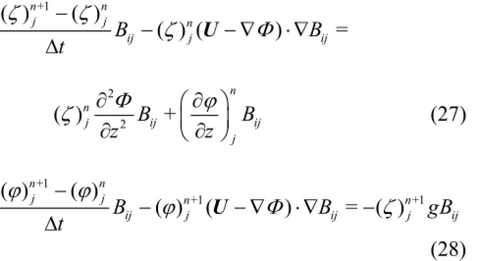
For the temporal discretization, a neutrally stable scheme named the “Emplicit Euler (EE)” is applied. The kinematic and dynamic free surface conditions are satisfied through the explicit and implicit schemes,respectively.
The discrete equations may be summarized as follows:


where the superscripts are the temporal indices and other terms are defined as

The evaluation of the integral in Eq.(30) over the panel is obtained by a Guassian quadrature rule.
In order to satisfy the radiation condition, the numerical damping beach approach is applied. Over the outer part of the free surface (see Fig.2), two numerical damping items are added into the kinematic free surface boundary condition as follows wheren is the so-called damping strength. Details about the numerical damping beach approach can be found in Huang[5].

3. Numerical results
3.1 Convergence study
The radiations of the Wigley I hull in heave and pitch are selected to test the convergence with respect to the mesh size and the time step. The Wigley I hull,defined in Journée[15], is expressed as


whereL is the model length,B is the full beam,and T is the draft. For the Wigley I hull,L/B=10 and B/T =1.6.

Fig.4 Spatial convergence of force and moment for Wigley I hull heaving at
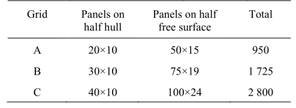
Figure 4 illustrates the spatial convergence of the vertical radiation force and moment for the Wigley model in heave atand the nondimensional frequencyThree different grids are tested with a common nondimensional time-step size ofThe grid numbers are shown in Table 1.

Table 1 The grids for the test of the spatial convergence
It can be seen that even when the hull grid is relatively coarse, namely, 20×10 panels on the half hull,the forces are already good with respect to convergence for both the heave-heave force (F3)and the heave-pitch moment (F5). This reflects the advantage of employing the quadric curved panel.

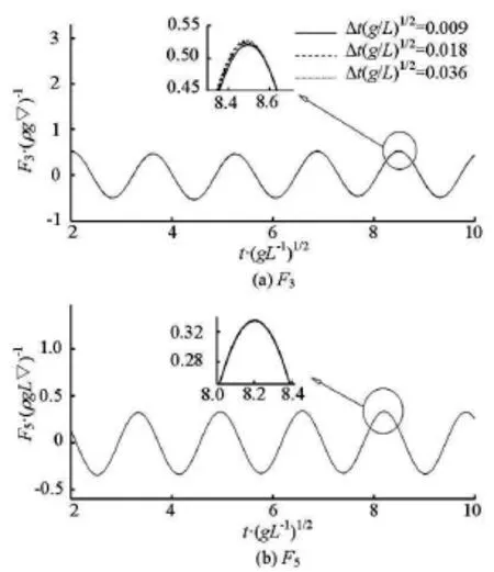
Fig.5 Temporal convergence of force and moment for Wigley I hull pitching at
Figure 5 illustrates the temporal convergence of the vertical radiation force and moment for the Wigley model in pitch at Fr =0.3andNumerical tests are conducted by using the same geometric discretization, namely, grid “B”, but different time steps of0.018 and 0.036. From Fig.5, it can be seen that the temporal convergence is adequate.

Table 2 Main particulars of the S-175 container ship
3.2 Radiation problem
After convergence studies, numerical simulations of the radiation are carried out to validate the aforementioned numerical method. Both the Wigley I hull and the S-175 container ship are tested. Compared with the Wigley hull, the S-175 containership has a significant flare at its bow and stern. The main particulars of the S-175 hull are listed in Table 2, and the line plan can be found in Fonseca and Guedes Soares[16].
The simulation time for each case is set to be ten times of the period of the forced oscillatory motion,and the second halves of the time histories of the radiation force are transformed into the frequency domain to evaluate the added mass and damping coefficients. The m-terms are determined by solving the boundary value problems of Dirichlet type, using the method proposed by Wu[17].

Fig.6 Hydrodynamic coefficients due to unit amplitude heave motion for the Wigley I model at Fr=0.2

Fig.7 Hydrodynamic coefficients due to unit amplitude pitch motion for the Wigley I model at Fr=0.2
The added mass and damping coefficients due to the forced heave and pitch motions for the Wigley I hull advancing at Fr =0.2are illustrated in Figs.6 and 7, which are compared with the experiments by Journée[15]. In order to identify the effect of the double body flow on the radiation forces, the Neumann-Kelvin (N-K) results are also included in the figures. It should be noted that the boundary value problem resulted from the classical N-K linearization is similar to Eq.(15), except the basis flow is simply set to be the uniform flow, i.e.Φ=0. Correspondingly, the mterms are simplified as

The comparisons show that the present results using the double-body linearization are in general better than the results using the N-K approach, especially for the prediction of the cross-coupling hydrodynamic coefficients (i.e.,a35,b35,a53and b53). The advantage of the present double body results is due to both the double-body m-term evaluations and the leading-order terms retained in the free surface boundary conditions (7) and (8) based on the double-body linearization.
For the diagonal coefficients, the present double body results and the N-K results compare well. However, a discrepancy can be found between the numerical results and the experimental ones, especially for the pitch-pitch coefficients a55and b55.

Fig.8 The exact and error vertical forces for the Wigley I hull inheave

Fig.9 The exact and error vertical forces for the Wigley I hull in pitch
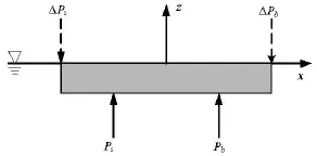
The discrepancy may be mainly due to the linearization of the boundary conditions. In order to make a clear explanation, denote Psand Pbas the resultantsof the exact z - component of the hydrodynamic pressures acting on the fore and aft parts of the hull, respectively,and the centers of the pressures on the fore and aft parts of the hull are assumed to be at the middle point of that section. It is reasonable to assume that the error forces, which are brought in by the linearization, act only on the bow and the stern, because the nonlinearities at the bow and the stern are muchstronger than at the middle part of the hull. In the following analysis, these error forces are denoted by∆Psand ∆Pb, for the stern and the bow, respectively.

Fig.10 Hydrodynamic coefficients due to unit amplitude heave motion for the S-175 at Fr=0.275

Fig.11 Hydrodynamic coefficients due to unit amplitude pitch motion for the S-175 advancing at Fr=0.275
When the Wigley I hull is forced to heave (see Fig.8),∆Psand ∆Pb.are of the same sign, therefore the summation of error forces will be added into the heave-heave force, which will result in an error in a33and b33. However, the error moments caused by ∆Psand ∆Pbwill cancel each other, so the prediction of the pitch-heave coefficients a53and b53is satisfactory. When the Wigley I hull is forced to pitch (see Fig.9),∆Psand ∆Pbare of the similar magnitude but of opposite sign. In this case, the prediction of the heave-pitch coefficients a35and b35is good because∆Psand ∆Pbcancel each other. But an error moment will be introduced. Although the magnitudes of ∆Psand ∆Pbare small, the long arm of the force (almost two times of the arm between Psand Pb) will amplify the error greatly. Therefore, the discrepancies in a55and b55between the numerical results and the experimental ones are more remarkable than those in a33and b33. For a more accurate prediction of these coefficients, a nonlinear computation might be necessary.
The hydrodynamic coefficients due to the forced heave and pitch motions for the S-175 container ship are shown in Figs.10 and 11. Since experimental data are not available, the numerical results by Zhang et al.[7]are used to validate the present numerical calculation. Their solution is based on the linearized free surface conditions and the exact body boundary condition.
In general, good agreement can be found between the numerical results from the present double body method and the method of Zhang et al.[7]. Discrepancies mainly occur in the prediction of the damping coefficients b53and b33. The reason for these discrepancies can be probably attributed to the different treatment of the body boundary condition.

Fig.12 Heave and pitch exciting forces and moments acting on Wigley I model at Fr=0.2
3.3 Diffraction problem
Numerical simulations of the diffraction are carried out for the Wigley I hull advancing in a regular head wave, with the forward speeds Fr =0.2 and 0.3. The nondimensional incident wave length λ/Lvaries from 0.75 to 2.0. Similar to the radiation force,the wave exciting force is also transformed into the frequency domain and compared with the N-K solutions and with the experimental data[15].

Fig.13 Heave and pitch exciting forces and moments acting on Wigley I model at Fr=0.3
Figures 12 and 13 show the results of the wave exciting forces and moments in heave and pitch, where c33and c55are hydrostatic coefficients,k is the incident wave number,A is the incident wave amplitude. From these comparisons it can be seen that the difference between the results obtained by using the double-body linearization and the N-K linearization is slight. Both sets of numerical results show good agreements with the experiments, for the force amplitude in both heave and pitch, as well as the phase lag angle in heave. However, discrepancies occur in the prediction of the phase lag angle in pitch. Similar discrepancies are also found in the results of Zhang et al.[18]. The reasons of these discrepancies are still unclear.

Fig.14 A snapshot of the heave radiation wave field

Fig.15 A snapshot of the diffraction wave field
3.4 Wave patterns
Figures 14 and 15 are the snapshots of the computed wave field for the heave radiation at4.0 and the diffraction at λ/L=1.25, respectively. The Froude number isFr=0.3. The effectiveness of the numerical damping bench is demonstrated since no reflection of waves is observed at the free surface truncation.
4. Concluding remark
A three-dimensional time domain Rankine panel method is used for solving the radiation and diffraction problems of a ship with a forward speed. A computer program is developed based on the algorithm. Numerical computations are carried for the Wigley I hull and the S-175 container ship, and the numerical results of the hydrodynamic coefficients and the wave exciting forces are compared with experimental results and other numerical solutions. The comparisons demonstrate that the present approach is promising.
Acknowledgement
This work was supported by the Lloydʼs Register Foundation (LRF). LRF helps to protect life and property by supporting engineering-related education,public engagement and the application of research.
References
[1] DATTA R., SEN D. A b-spline solver for the forwardspeed diffraction problem of a floating body in the time domain[J]. Applied Ocean Research, 2006, 28(2): 147-160.
[2] DUAN W., DAI Y. Integration of the time-domain Green function[C]. Twenty-second International Workshop on Water Waves and Floating Bodies. Plitvice, Croatia, 2007.
[3] ZHU Ren-chuan, ZHU Hai-rong and SHEN Liang et al. Numerical treatments and applications of the 3D transient green function[J]. China Ocean Engineering,2007, 21(4): 92-101.
[4] NAKOS D. E., KRING D. C. and SCLAVOUNOS P. D. Rankine panel methods for transient free-surface flows[C]. Sixth International Conference on Numerical Ship Hydrodynamic. Iowa City, USA, 1993.
[5] HUANG Y. Nonlinear ship motions by a Rankine panel method[D]. Doctoral Thesis, Cambridge, MA, USA: Massachusetts Institute of Technology, 1997.
[6] KIM Y., KIM K. and KIM J. et al. Time domain analysis of nonlinear motion responses and structural loads on ships and offshore structures: Development of WISH programs[J]. International Journal of Naval Architecture and Ocean Engineering, 2011, 3(1): 37-52.
[7] ZHANG X., BANDYK P. and BECK R. F. Time-domain simulations of radiation and diffraction forces[J]. Journal of Ship Research, 2010, 54(2): 79-94.
[8] YASUKAWA H. Time domain analysis of ship motions inwaves using BEM (2nd Report: Motions in regular head waves)[J]. Transactions of the West-Japan Society of Naval Architects, 2001, 101: 27-36.
[9] HE G., KASHIWAGI M. A time-domain higher-order boundary element method for 3D forward-speed radiation and diffraction problems[J]. Journal of Marine Science and Technology, 2014, 19(2): 228-244.
[10] CHEN Jing-pu, ZHU De-xiang. Numerical simulations of wave-induced ship motions in time domain by a Rankine panel method[J]. Journal of Hydrodynamics,2010, 22(3): 373-380.
[11] CHEN Jing-pu, ZHU De-xiang. Numerical simulations of wave-induced ship motions in regular oblique waves by a time domain panel method[J]. Journal of Hydrodynamics, 2010, 22(5): 419-426.
[12] CHEN Jing-pu, ZHU De-xiang. Numerical simulations of nonlinear ship motions in waves by a Rankine panel method[J]. Chinese Journal of Hydrodynamics, 2010,25(6): 830-836(in Chinese).
[13] NEWMAN J. N. The theory of ship motions[J]. Advances in Applied Mechanics, 1978, 18: 221-283.
[14] SALOMON D. Curves and surfaces for computer graphics[M]. New York, USA: Springer, 2005.
[15] JOURNÉE J. M. J. Experiments and calculations on four Wigley hull forms[R]. Technical Report 909. Delft,The Netherlands: Delft University of Technology, 1992.
[16] FONSECA N., GUEDES SOARES C. Comparison of numerical and experimental results of nonlinear waveinduced vertical ship motions and loads[J]. Journal of Marine Science and Technology, 2002, 6(4): 193-204.
[17] WU G. A numerical scheme for calculating the mjterms in wave-current-body interaction problem[J]. Applied Ocean Research,1991, 13(6): 317-319.
[18] ZHANG X., BANDYK P. and BECK R. F. Seakeeping computations using double-body basis flows[J]. Applied Ocean Research, 2010, 32(4): 471-482.
(April 3, 2014, Revised August 16, 2014)
* Project supported by the National Natural Science Foundation of China (Grant No. 51279106).
Biography: ZHANG Wei (1983-), Male, Ph. D. Candidate
ZOU Zao-jian,
E-mail: zjzou@sjtu.edu.cn
- 水动力学研究与进展 B辑的其它文章
- Classification of flow regimes in gas-liquid horizontal Couette-Taylor flow using dimensionless criteria*
- MHD flow of a visco-elastic fluid through a porous medium between infinite parallel plates with time dependent suction*
- Polymer flow through water- and oil-wet porous media*
- Hydrodynamics and modeling of a ventilated supercavitating body in transition phase*
- Numerical analysis of the unsteady behavior of cloud cavitation around a hydrofoil based on an improved filter-based model*
- Thermal instability and heat transfer of viscoelastic fluids in bounded porous media with constant heat flux boundary*

