Advances of drag-reducing surface technologies in turbulence based on boundary layer control*
LUO Yuehao, WANG Liguo, GREEN Lork, SONG Kenan, WANG Liang, SMITH Robert
1. School of Engineering and Applied Science, The George Washington University, Washington DC 20052, USA,E-mail: luoyuehao1985@163.com
2. Division of Electricity, Department of Engineering Sciences, Uppsala University, Uppsala 75121, Sweden
3. School of Engineering, Boston University, Boston, MA 02215, USA
4. Department of Mechanical and Industrial Engineering, Northeastern University, Boston 02115, USA
5. Department of Mechanical Engineering, University of Colorado at Boulder, Boulder 80309, USA
6. College of Applied Sciences and Technology, Ball State University, Muncie 47306, USA
Advances of drag-reducing surface technologies in turbulence based on boundary layer control*
LUO Yuehao1, WANG Liguo2, GREEN Lork3, SONG Kenan4, WANG Liang5, SMITH Robert6
1. School of Engineering and Applied Science, The George Washington University, Washington DC 20052, USA,E-mail: luoyuehao1985@163.com
2. Division of Electricity, Department of Engineering Sciences, Uppsala University, Uppsala 75121, Sweden
3. School of Engineering, Boston University, Boston, MA 02215, USA
4. Department of Mechanical and Industrial Engineering, Northeastern University, Boston 02115, USA
5. Department of Mechanical Engineering, University of Colorado at Boulder, Boulder 80309, USA
6. College of Applied Sciences and Technology, Ball State University, Muncie 47306, USA
Our living environment is surrounded by turbulence, which is also a concern of the global energy consumption and the greenhouse gas emission, and the viscous force on the solid-liquid/solid-gas interface is an important part of the turbulence. Reducing friction force in turbulence to the greatest extent is becoming an urgent issue to be resolved at present. In this paper, the various state-of-the-art approaches of drag-reducing and energy-saving technologies based on the boundary layer control are reviewed, focusing on the polymer drag reduction additives, the micro-morphology, the super-hydrophobic surface, the micro air bubbles, the heating wall, the vibrant flexible wall and the composite drag reduction methods. In addition, the mechanisms of different drag reductions based on the boundary layer control and the potential applications in fluid engineering are discussed. This paper aims not only to contribute to a better understanding of drag reduction mechanisms, but also to offer new perspectives to improve the current drag-reducing and energy saving technologies.
fluid drag reduction, hydrodynamics, energy saving, turbulent flowing, boundary layer control
Introduction
All objects in the world are in a constant moving state, and when the fluid velocity is above a threshold,turbulence comes in Refs.[1,2]. The viscous drag friction on the interface in different phases is ubiquitous,especially in the cases of airplanes, steamships, automobiles, natural gas/oil pipelines, high-speed railway train, fire-fighting equipment, and swimming suit. Viscous force is directly proportional to the square of the corresponding fluid speed, and causes the consumption of energy and the emission of greenhouse gases[3]. The drag reduction technology in turbulence is now a hot research issue and attracts ever increasing attentions throughout the world. The traditional viewpoints are of the opinion that “with the decrease of roughness on the contact surface, the friction will definitely become less”, and they are validated and applied in different fields for a long time, with commercial successes. However, the above mentioned wellknown concept is facing a serious challenge from the recent research achievements in fluid engineering[4-7].
The numerical simulations and the fluid experiments have confirmed that if the thickness of the viscous sublayer is greater than the roughness of the contact surface, all small convex parts can be completely incorporated into the viscous sublayer. Under such a condition, the interface can be called hydrodynamically smooth, the friction force will be transformed into the viscous resistance, which cannot be reduced further even by lowering the roughness on the interface[8-10], and the traditional concept cannot work any longer. Therefore, the novel methods and approaches to reduce the drag based on the “hydrodynamically smooth” interface should be explored further. In the1980s, Reif et al.[11]discovered that there were very sophisticated and complicated morphologies to be found on sharkskin scales, which could illustrate the drag reduction effect under certain turbulent conditions as compared to the absolutely smooth or hydrodynamically smooth surfaces. Lotus leaf is well known for its self-cleaning function, and the micro/ nano structures on the lotus leaf surface were reported to account for the super-hydrophobic effect. The slipping phenomenon in the boundary layer was observed and validated, which implies that the fluid flowing velocity can be increased dramatically with the same power loss[12-15]. Dolphin has a flexible skin, and the turbulence on its skin can be inhibited and buffered to a some degree, to ensure both high swimming speed and low consumed energy[16-18]. Additionally,the drag reduction polymer additives, the air bubbles,the heating wall excited vibration and the composite methods can also be regarded as important approaches to reduce the viscous drag in turbulence. The above mentioned technologies are not based on the traditional concepts, and these novel ways of drag-reducing techniques are increasingly extending the horizon of applied mechanics, with huge potentials in practical engineering.
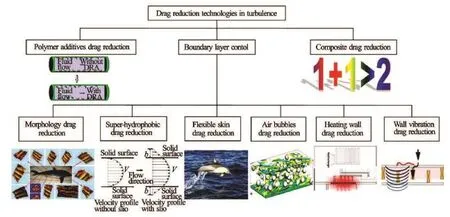
Fig.1 Different drag reduction technologies in turbulence
In this overview, firstly, various kinds of drag reduction technologies in turbulence based on the boundary layer control are summarized, as shown in Fig.1. Secondly, different drag reduction hypotheses are explored and discussed from different aspects. Lastly,the potential applications in practical engineering are presented. The paper aims to better comprehend the current research status of drag reduction techniques in turbulence.
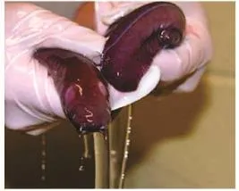
Fig.2 Slime covered on fish skin
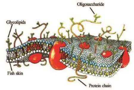
Fig.3 Schematic diagram of mucus on fish skin
1. Polymer additives drag reduction
Generally speaking, the biological skin surfacesof most fish are covered with slime, as shown in Fig.2,which serves as the first medium to contact with the outside world and has the functions of drag reduction,immunologic defense, osmotic pressure adjustment,and PH value regulation[19,20]. A large number of mucus goblet cells are embedded into the biological skin epithelial tissue, and their secretions are mainly composed of polysaccharide-protein and fiber materials, which can be turned into mucus combined with water after the release of these substances from the mucous cells[21,22], and a schematic diagram is shown in Fig.3. The natural sharkskin enjoys an excellent drag reduction performance due to its hierarchical structure built up by microgrooves and nano-long chain mucus drag reduction interface around the shark body. The same as most fish, the sharkskin can secrete mucus, with the function of keeping out of fungus and reducing the viscous friction[23].
For enhancing the flowing property, the polymer additives, as the drag reduction agent (DRA), are utilized widely, which was firstly introduced by Toms in the 1940s, and the drag-reducing rate may increase by 30% as compared to the original fluid[24]. Many research progresses were made in the field during the last more than 70 years. Two different hybrid approaches to synthetically combine the vivid shark skin and the polymer additives were put forward by Chen et al.[25],and the testing results in a water tunnel show that the peak of the drag-reducing rate could be over 60% with the smooth skin as the baseline under some conditions.
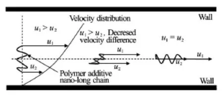
Fig.4 Rotation-redirection of drag reduction polymer additive nano-long chain
The drag reduction mechanism of the polymer additives has been extensively studied, but remains a challenging issue[26-28]. The polymer additives can be transformed into nano-long chains under the induction effect of liquid, which can stretch naturally into the viscous sublayer of the flowing liquid, and the turbulent flow can be calmed down into an ordered and regular state[29]. Firstly, the thickness of the viscous sublayer is increased, which can enhance the buffering function on the near wall. Secondly, the slipping effect on the fluid-solid interface can lead to a decrease of the velocity gradient and the viscous drag. Thirdly, the stretched nano-long chains can weaken the turbulence intensity by the calming effect. In a word, the more steady flowing conditions in the boundary layer can be secured due to the existence of the nano-long chains of polymer additives[30,31]. With the polymer additive nano-long chains in turbulence, different speeds will be reached at the nano-long chain ends, and the nano-long chains will rotate to reduce the speed difference. Ultimately, the chains reach a balance at positions parallel to the pipe flow, to realize the drag-reducing function[32]. This process can be regarded as the rotation-redirection effect, and the schematic diagram is shown in Fig.4.
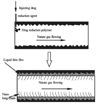
Fig.5 Application of drag reduction agent additives to natural gas pipelining
Experiments and practical applications have confirmed that the mucus/polymer additives have the drag reduction effect in the liquid. The recent reports indicate that the drag reduction agent (DRA) can also be utilized on the solid-gas interface[33,34], especially on the natural gas pipelining. Injecting the DRA is a good practice to reduce the friction and increase the throughput for the service natural gas pipelines. The DRA is selected from a class of chemical compounds, of molecular structures having a polar group at one end,to be bonded onto the inner wall of the pipeline and of those having a non-polar group at the other end, to smooth the gas-solid interface between the inner wall and the flowing natural gas, thereby reducing the gas turbulence on the interface[35]. The schematic diagram of applying the drag reduction agent into the natural gas pipelining is shown in Fig.5. A field test of a natural gas pipeline in the Gulf of Mexico was conducted in 2000, and the results show that the peak gas production rate could be increased by 10%-15% and the peak pressure drop could be decreased by up to 20%[36], and the feasibility and the reliability of theDAR application to the gas-solid interface are confirmed.
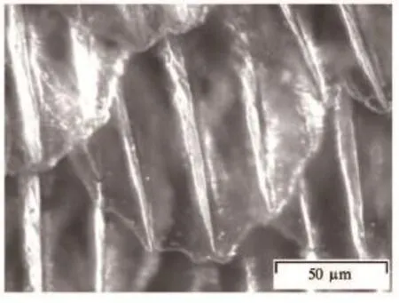
Fig.6 Morphology of sharkskin surface
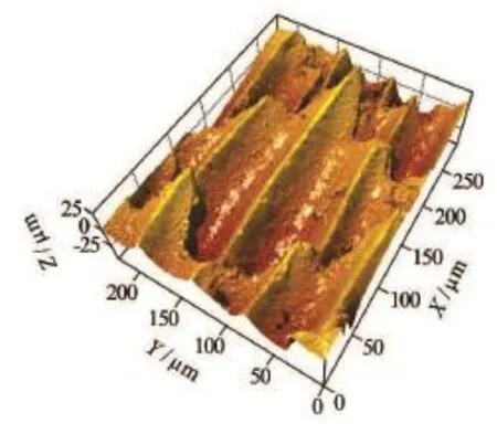
Fig.7 Three-dimensional morphology of sharkskin scale
2. Micro-morphology drag reduction
Through millions' years of natural selection and evolution, different fauna and flora gradually formed their own special functional surfaces[37-39]. Shark is one of the fastest swimming animals in the ocean, and it is a consensus that the shark's amazing speed is not only due to the streamline shape of its body, but also due to the sophisticated and hierarchical nano/micro structure on its skin[40,41]. The whole surface of the shark is covered by tiny and rigid scales[42,43], the twodimensional and three-dimensional images are shown in Fig.6 and Fig.7, respectively, and it can be observed that biological sharkskin scales are semi-transparent,and the size of the scale is basically 200 µm×200 µm× 30 µm (L×W×H).
In the last several decades, the sharkskin effect has been amply studied and put into applications. Walsh summarized the optimized parameters of the micro-groove height and width, which have an important influence on the drag reduction efficiency and laid a foundation of the biomimetic drag-reducing technology[44]. Berchert et al. conducted hydrodynamic experiments in water and oil tunnels, and the experimental results show that the maximum drag-reducing rate of the bio-inspired sharkskin surface is approximately 10%[45,46]. The flow fields over the microgrooved surface were analyzed by Choi, and it was concluded that the ratio of the groove height to width should be in some range, otherwise, the drag reduction effect could be weakened or disappear[47]. Dean and Bhushan investigated various hierarchical nano/micro textured biomimetic surfaces, with their obvious and striking drag reduction, self-cleaning, low adhesion,water repellent and anti-fouling functions, which have the potential to be applied into practical engineering[48,49]. The influence of the bristled sharkskin scales based on the boundary layer control was explored,and it is concluded that the scales could be pliable and even erect under the external factors, which might contribute to the high drag-reducing effect of the biological sharkskin surface[50,51]. The bio-replicated method with the biological sharkskin as the direct template was put forward by Han and Zhang, and the artificial sharkskin made of silicon rubber was fabricated with lower viscous force beyond 8%[52,53]. The continuous sharkskin drag-reducing surface was manufactured by the bio/micro rolling method, the drag-reducing efficiency compared to the smooth skin could be more than 10%[54]. To elucidate the drag reduction mechanism over the real sharkskin surface, an accurate digital model was constructed to perform the direct numerical simulation, and it is shown that the attack angles of the scale are related with the back flowing phenomena on the slope surface, which could be regarded an important factor for the high drag reducing rate of the real sharkskin[55,56]. Liu investigated the drag reduction performance of the bio-inspired sharkskin micro riblets in pipes, and the drag reduction efficiency of more than 7% in the completely developed turbulence was acquired[57]. The drag-reducing surfaces with deformed sharkskin textures were manufactured by the stretching method, and it was discovered that the super-hydrophobic effect could be obtained obviously, and in the meanwhile, the optimal speed range with a high drag-reducing rate could be extended to some degree[58]. The micro flow field over the micro-grooved pattern in different directions was observed and measured, and the experimental results show that the viscous force could be lowered by about 10%[59]. Wen et al. produced thousands of enlarged real sharkskin scales, and the testing results show that the energy cost-of-transport was reduced by 5.9% with the smooth skin as in reference[60]. Motta et al. explored the micro morphology and the flexibility of sharkskin scales, it is concluded that on the shortfin mako shark, there is a region of highly flexible scales on the lateral flank that could be erected by at least 50o[61]. The precise cutting method with the Hardinge machine was adopted to fabricate the micro-groovedsurfaces with different sizes, and they were applied to achieve the drag reduction function under different flowing conditions[62]. Hydrodynamic experiments of pipes with a V-shaped texture simulating the sharkskin morphology were conducted in a water tunnel,and it was reported that all pipes show a lower viscous force effect in different levels[63]. Park explored the micro-forming method for the shark skin replication,which could extend the micro fabrication horizon dramatically, and meanwhile, a more reliable and accurate evaluating approach was put forward[64]. The sharkskin scale could be moveable within angles greater than 50o, and the movable shark scales could act as a passive dynamic micro-roughness to control the flow separation[65]. The influence of the Reynolds number on the drag reduction effect of the micro-grooved surface was analyzed by the direct numerical simulation method, and a review shows that the drag-reducing efficiency could surpass 6% and the secondary vortex generated at the tips is a fundamental factor to produce low friction[66]. Vivid trans-scale sharkskin surfaces were fabricated by the three dimensional printing method, and a fair picture of the sharkskin could be made,and at the same time, the method has the potential to be applied into the fluid with high viscosity[67]. All in all, an undisputable fact is shown that the bio-inspired sharkskin morphology has an obvious drag reduction effect compared to the smooth skin in turbulent flowing states.

Fig.8 Important milestones in studies of sharkskin effect and practical applications
The important milestones in the studies of the sharkskin mechanism and the applications in practical engineering are shown in Fig.8.
The explanation of the sharkskin drag reduction effect concerns various turbulence theories, some critical and fundamental issues are not solved adequately, and the drag reduction mechanism of the micro-morphology remains to be explored. The following points can be regarded as possible hypotheses for the sharkskin effect[21-23]:
(1) Generally speaking, the depth of the viscous sublayer on the sharkskin surface is less than 10 µm, while the height of the scale can be greater than 20 μm, therefore, the tips of the micro-groove can inevitably protrude the viscous sublayer[55,56]. On one hand, the turbulence near the wall can be calmed down by the protruding height, which can regulate the turbulence structure and lower the turbulence intensity[45,46]. On the other hand, the secondary vortex can be generated by the smashing function between the original vortex and the micro groove tips, the consequence of which can weaken the turbulence intensity further[66].
(2) The longitudinal section of the sharkskin scale is not exactly parallel to the flowing direction, but at a certain attack angle, ranging from 10o-50o. Due to the existence of an attack angle, the back flowing of the micro water droplets might exist on the slope of the sharkskin scale, which enables the flowing movement to be more steady and decreases the turbulence intensity. And additionally, the back flosistance is reduced again[56,58]. wing can produce an opposite force, hence the wall re-
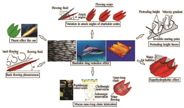
Fig.9 Different potential factors generating sharkskin drag reduction effect
(3) The biological sharkskin surface is covered by the mucus, which can be transformed into nanolong chains with the induction of liquid water. On one hand, the mucus nano-long chain has the lubrication effect and can help to increase the thickness of the viscous sublayer, and the slipping can be produced on the fluid-solid interface, which can lead to the decrease of the velocity gradient and the viscous friction. On the other hand, the turbulence intensity can be weakened further by the calming function. In a word, a more steady flow condition in the boundary layer is thus ensured with the existence of mucus nano-chains[21,68,69].
(4) The sharkskin morphology is very sophisticated and complicated, and it is developed into one kind of super-hydrophobic surfaces. The air can be entrapped into the bottom of the micro texture, and the viscous force on the liquid-solid interface can be replaced by that on the gas-solid interface, so the viscous friction can be reduced significantly. And additionally, the slipping on the boundary layer can be generated, and therefore, the drag reduction effect can be strengthened further[70].
(5) The scales are deeply embedded into the flexible dermal tissues of the biological sharkskin, although they are rigid, the attack angles between the longitudinal section of the scale and the flowing direction are not fixed, but varying according to the outside flowing states during shark's swimming, which is another non-negligible factor to produce the high drag reduction efficiency[21,56].
(6) The sharkskin scales can erect to some degree during shark's swimming, which has a thrust function, just as the oar of the boat[21,71]. On one hand, the micro morphology on the sharkskin can decrease the viscous force, and on the other hand, the erected scales have the thrust effect like the oar. Therefore, the combined function can explain the high drag-reducing effect.
The schematic diagram of different potential factors generating the sharkskin effect is shown in Fig.9.
Due to the superiorities of the biomimetic sharkskin surface in the functions such as drag reduction,anti-fouling, self-cleaning, anti-wear, and water repellence, it has huge potential applications in fluid engineering, and even some practical applications.

Fig.10 Potential applications of sharkskin surface in fluid engineering

Fig.11 Different super-hydrophobic biological functional surfaces
Luo et al.[72-74]put forward a bio/micro rolling method to manufacture the micro-grooved texture in a large area, and the method has successfully applied in the natural gas industry, and the field testing with natural gas shows that the pressure drop could be decreased by more than 8%, with many profits. Spitz was awarded seven gold medals wearing briefs and Phelps earned 14 gold medals in Athens and Beijing wearing a high-tech all-over bodysuit, and in 2010 the high-technology swimsuits, as significantly improve the performance, were banned from competition. The above mentioned fact indicates that the bio-inspired sharkskin drag reduction swimming suit has become a commercial product[75]. The bio-inspired morphology has found applications in the golf ball surface, the purpose of which is to make it fly farther and more controllable[76]. The sharkskin inspired riblet structures have been introduced onto the aero-engine, and the experimental results show that the riblet structures prior to oxidation reduce the wall shear stress of up to 4.9% as compared to a normal smooth surface[77]. The bio-inspired sharkskin surface has been put into applications on the ship surface, andthe pore settlement is reduced by 85% on the finer and more complex biomimetic sharkskin topographies[78]. With about 70% of the aircraft surface covered with 3M riblets, the testing results show a total drag reduction of about 2% in the Mach number range of 0.77-0.79, as is extremely significant in the actual flight applications[79].
All in all, there is a great possibility to develop the bio-inspired sharkskin technology into fluid engineering, such as natural gas/oil pipelining, airplane,ship, oil well platform, windmill, swimming-suit,high-speed train, and racing car, as shown in Fig.10.
3. Super-hydrophobic surface drag reduction
The diversity of fauna and flora surface structures is the result of evolution of over 460 million years on the earth, with a large variety of highly adapted special functional structures obtained by strict natural selections. The super-hydrophobic surface is defined as a surface possessing a contact angle greater than 150owith respect to a small water droplet. Many creatures' skins show an excellent superhydrophobicity, such as lotus leaf, butterfly wing, water stride legs,fly eyes, and rice leaf[80-83], as shown in Fig.11.
In the super-hydrophobic surfaces in nature, hierarchical nano/micro structures were discovered, such as the micro grooves, micro pillars, and micro dents. With the existence of the hydrophobic surface layers,a super-hydrophobic state was observed. The water droplets falling on the surface bound and roll off the surface instantaneously. The super-hydrophobicity requires that both the surface hydrophobic layer (low surface energy) and the rough surface structures are present. It is well-known that the contact angle can be an important standard to evaluate the super-hydrophobic effect. On an ideal, smooth surface, the droplet wetting at the equilibrium static state is usually described by the intrinsic contact angle (θ), defined by Young's equation[84]
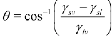
where γsv,γsland γivare the solid-vapor, solidliquid, and liquid-vapor interfacial tensions, respectively. On this basis, Cassie and Wenzel proposed twodifferent mechanisms to describe the surface roughness effect of the equilibrium droplet wetting on the super-hydrophobic surfaces, defined as follows[84,85]:

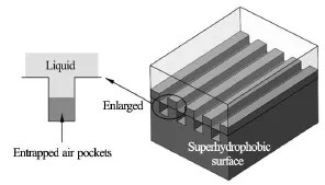
Fig.12 Schematic diagram of water impregnating over superhydrophobic surface
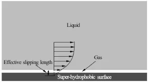
Fig.13 Effective slipping length
For the super-hydrophobic surface with a microgrooved texture, the air-pockets will be entrapped into the bottom of the micro structures, as shown in Fig.12,and the water droplets can be lifted by compressed air,which can lead to a great contact angle. The air bubbles in the cavity are not steady, they can revolve at some speed, and they may have the function of bearing. In the meanwhile, due to the induction of the gas,the viscous force on the liquid-solid interface is replaced by that on the gas-solid interface, on the boundary between a viscous fluid and a solid surface, where the fluid velocity with respect to the surface might be assumed to be zero, which implies that there is no slipping. In some situations, the air pockets are stably entrapped between the surface features, the velocities on the top and bottom of the gas cushion are different,thereby creating a significant effective slipping area on the surface, as illustrated in Fig.13, and the effective slipping length can serve as an important evaluation for the super-hydrophobicity. The super-hydrophobic surfaces have attracted much attention lately as they present the possibility of achieving a substantial skin-friction drag reduction in both laminar and turbulent flowing states, and additionally, the drag reduction efficiency is very striking under some conditions,which can be greater than 20%[86].
The water on the super-hydrophobic surfaces can form small beads with a high contact angle and drip off rapidly when the surfaces are slightly inclined,while taking away the powder-like contaminants. This fascinating phenomenon has stimulated extensive research to make artificial super-hydrophobic surfaces. The super-hydrophobic/self-cleaning technology has been developing gradually since the late twentieth century, and some achievements have led to the practical applications in different fields. A large number of studies have been conducted to further develop the super-hydrophobic technologies including anti-smudge, anti-fouling, low adhesion, low drag, anisotropic wetting, anti-reflection, directional adhesion, photocatalysis, and self-sterilizing technologies[87]. They found applications in micro-material energy, fuel transportation, optical instruments, biological media,metal anti-rusting, battery electrode, weaving cloth and so on.
4. Air bubbles drag reduction
To investigate the drag-reduction and explore the practical applications in turbulent boundary layers in large scales and for high Reynolds numbers (Re), various approaches were adopted, in which, the air bubble drag reduction is a good attempt. The drag-reducing function is realized by injecting gas, which leads to two distinct drag-reducing phenomena, the bubble drag reduction, and the air layer drag reduction[88]. Experimental results of the air bubble drag reduction show that a significant drag reduction of greater than 25% could be made in the first few meters downstream of injection, and meanwhile, a marginal improvement is possible with a porous-plate instead of an open-slot injector design[88]. Sanders realized the dragreducing and the energy-saving with the air bubbles at high Reynolds numbers, and the experimental results show that significant levels of bubble drag reduction could be achieved near the gas injection locations[89]. It was discovered that a gas layer could be formed on the underside of the flat plate, with the lubricated and drag-reducing function, and a skin-friction reduction of greater than 80% was measured[88,89].
Because some fundamental principles in fluid en-gineering have not been made very clear, the underlying physical mechanism of the air bubble drag reduction has not yet completely understood and explained. The generally accepted consensus is as follows. For bubbles to reduce the skin-friction, the turbulent momentum exchange in the buffer region and the boundary layer should be reduced in some way[88]. It was hypothesized that the viscosity in the buffer region might be strengthened by the presence of local bubbles, with the consequence of reducing the turbulent fluctuation levels and increasing the thickness of the sub-layer and the buffer region of the turbulent boundary layer[90]. The results of Druzhinin indicate that the bubbles might migrate to the vortex cores in a turbulent shear flow and reduce the turbulent fluctuations[91]. The numerical simulations of the air bubbles in turbulence were made, and the mechanism of the bubble drag reduction at relatively low Reynolds numbers was discussed and explained[88]. Kumagai et al.[92]developed a novel drag-reducing and power-saving device to lower the drag of a ship' hull adopting the micro air bubble technology, as shown in Fig.14, and the experimental results show that the drag reduction is in the range of 5%-15%.
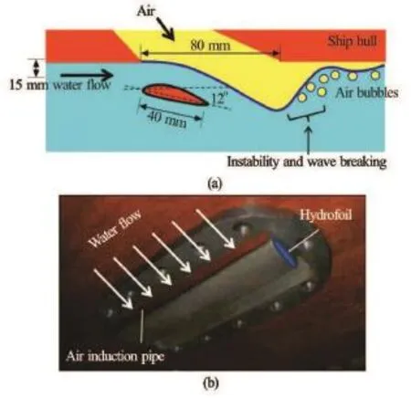
Fig.14 Schematic disgram and the field image of winged air induction pipe
All in all, the reliability of the air bubble drag reduction in turbulence was validated[92-95], and it has huge potential applications in fluid engineering, such as for ships and boats.
5. Other drag reductions
5.1Vibrant flexible wall drag reduction
In the context of the global energy shortage and the green house gas release, it becomes an important issue reducing drag on the two phase interface, and the vibrant flexible wall was proposed to reduce the skin friction drag.
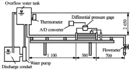
Fig.15 Schematic diagram of experiment devices
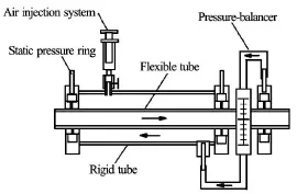
Fig.16 Schematic diagram of testing structure with flexible double-tubes

Fig.17 Schematic diagram of combining nano-long chains and sharkskin morphology
It was reported that dolphins could make effortless high-speed swimming by an air-breather perfectly adapted in an aquatic environment, as a consequence of the natural selection in a long history[17]. Various hypotheses were proposed to explain this high-speed and effortless swimming. Generally speaking, the vibrant flexible wall drag reduction can be attributed to the dolphin flexible/soft biological skin, which might find successful biomimetic applications in practical engineering. The drag reduction effect may be simulated as a coupling between the flexible tubes and the interior turbulent flow field, which changes the original turbulence layer structure near the rigid wall. Caiet al. conducted the drag reduction experiments of the coupling flexible tubes to clarify the mechanical characteristics, as shown in Fig.15 and Fig.16, and the results show that the thinner the flexible tubes and the larger the Reynolds numbers, the greater the drag reduction rates will be. Meanwhile, the maximum drag reduction efficiency could surpass 10%[96,97].
Although the drag reduction mechanism of the vibrant flexible wall was explored and investigated extensively, some fundamental issues remain unsolved. It is not easy for the flexible wall to get practical durability and easy maintenance with a reasonable cost[98]. The vibrant solid wall can be put into applications in cars or ship bodies, in which, the drag reduction is basically achieved by the velocity distribution near the wall surface. It is maintained that the reduction of the skin friction drag on a vibrant wall is mainly caused by the decrease of the Reynolds shear stress, and the effect of the shear stress due to the velocity gradient near the wall is small, and therefore, the total friction force is lowered down to some extent[99].
The above facts show that the vibrant flexible wall drag reduction technology could be potentially applied to the fluid engineering, such as racing car,ship, and boat. However, how to maintain the high drag-reducing effect under most flowing conditions remains a challenge.
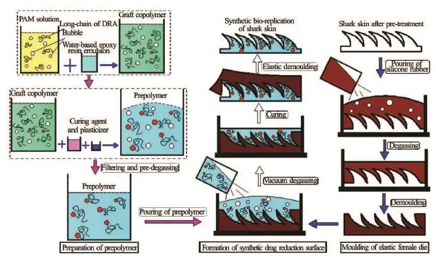
Fig.18 Synthetic bio-replication of sharkskin process
5.2Heating wall drag reduction
For most fluids, with the increase of temperature,the viscosity will be reduced gradually. According to the theory of fluid mechanics, the viscous force depends on the velocity and the viscosity, and therefore, the heating wall drag reduction is one important approach of realizing energy saving in fluid engineering.
The natural convection of gases over an isothermally heated wall of a vertical annular micro-channel was studied analytically by Weng et al, and it is shown that the nonlinear temperature profile due to the curvature effect plays an important role in the flow drag and the heat transfer[100]. The relationship between the drag reduction efficiency and the heat transfer reduction was investigated by Liet et al, and it is shown that when the drag reduction induced by the drag-reducing polymer is in the range of 60%-70%,the heat transfer between the flowing fluid and the pipe wall might be apparently decreased. Meanwhile,the heat transfer could reach up to 80%-90%[101]. The heating wall drag reduction is basically for the fluids whose viscosity has the direct relationship with temperature.
6. Composite drag reduction
With different drag reduction technologies based on the boundary layer control in turbulence discussed above, it can predicted that if two or more technologies are combined together, the drag reduction effect may be improved dramatically. Zhang proposed a novel and facile synthetic bio-replication forming approach for simultaneously grafting nano-long chains to bio-replicated micro-grooves of the sharkskin[102], and the fundamental schematic diagram is shown in Fig.17. Generally speaking, the drag reduction efficiency of the micro-grooved surface is about 8%, and the drag reduction efficiency of the polymer additives can begreater than 10%, and due to the coupling effect, the synthetic drag reduction of micro-grooved surface with polymer additives can be beyond 20%, or even higher.
Based on the coupling effect hypothesis, the composite drag reduction method was put forward in 2011, composed of the direct morphology bio-replicated forming and the drag reduction agent nano-long chain grafting, as shown in Fig.18. The main procedures of the composite drag reduction are as follows. (1)The pretreatment of the biological sharkskin template[52,53], to maintain the micro-grooved texture and improve the strength. (2) Molding of the flexible female die, in which the vacuum degassing is indispensible.(3) Fabrication of the composite drag reduction surface. The synthetic bio-replication combined soft die forming and grafting technology, with advantages,such as the high replication precision and the saving of drag reduction agent, provides an effective approach for the manufacture of synthetic drag reduction surfaces[102].
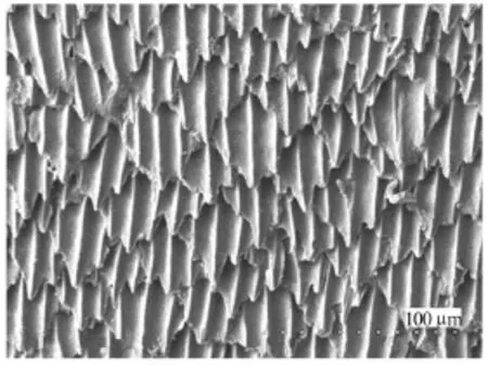
Fig.19 SEM image of composite drag reduction sharkskin
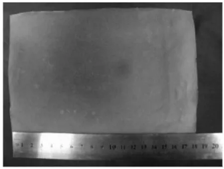
Fig.20 Sample of composite artificial sharkskin
The images of the composite drag reduction sharkskin surface are shown in Fig.19 and Fig.20. It can be seen that there is no obvious impefections on it,and the experimental results show that the replicating precision can be better than 95%. On one hand, the manufacturing horizon is extended, and on the other hand, it serves as another approach to achieve a high drag reduction effect in fluid engineering.

Fig.21 Hydrodynamic drag reduction testing in a water tunnel
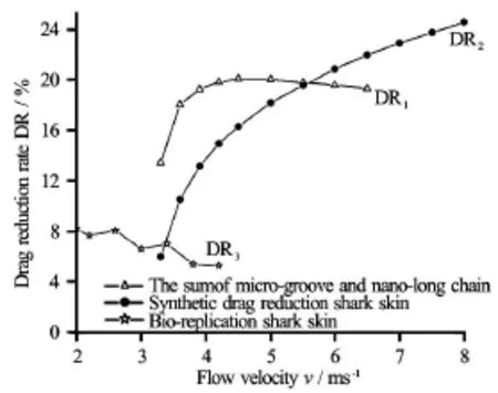
Fig.22 Drag reduction efficiency of different skins
To validate the composite drag reduction effect,the hydrodynamic experiments were conducted in a vacuole water tunnel at the China Ship Scientific Research Center, as shown in Fig.21. It is shown that the drag reduction rate of the composite drag reduction sharkskin surfaces is increased steadily with the increase of the flow velocity with a remarkable drag-reducing effect, reaching up to 24.6% during the test process[102], as shown in Fig.22, much greater than the sum of of the rates obtained by the micro-morphology and the polymer additives drag reduction individually. In a word, the composite drag reduction technology has a bright future for the drag reduction in fluid engineering.
7. Comparison of different drag reduction technologies
In this section, the drag-reduction efficiencies of different drag reduction technologies are summarized for comparison, and their advantages and disadvantages are illustrated, as shown in Table 1.

Table 1 Comparison of different drag reduction technologies
8. Future studies
Various drag reduction technologies were investigated and exploited in fluid engineering, as well as the drag-reducing mechanisms[103,104], but there are still some problems remain unsolved completely as follows:
(1) For some drag reduction surfaces, a perfect drag-reducing effect can be seen under certain conditions, and if the flowing conditions are changed, the drag-reducing effect will be weakened or disappear. How to improve the application range is an important issue.
(2) How to protect the drag reduction surface from damage and pollution should be explored further,for example, if the surfaces are covered with the dusts in practical applications, the drag-reducing function can be decreased to some extent, and even turned into a minus effect.
(3) Some experiments and theoretical analyses are still in the stage of laboratory research, and there is long way to be applied in the practical engineering. Accelerating the application process in practical engineering and industry is another serious problem.
For all drag reductions, the composite drag reduction has the brightest future. Due to the coupling effect, the synthetic drag reduction efficiency is more than the sum of those obtained by individual drag reduction methods. Of course, the utilizing conditions should be explored further.
9. Conclusions
In this paper, different kinds of drag-reducing/ energy saving technologies in turbulence are illustrated systematically and comprehensively, and additionally, the drag-reducing mechanism is elucidated and discussed from different aspects, and the following conclusions can be acquired:
(1) Additives can reduce the viscous drag force greatly, and the drag reduction rate can surpass 30%. However, in order to maintain a high drag reduction effect, the supplement step for the additives is imperative, and additionally, it can pollute the fluid to some extent.
(2) The micro morphology drag reduction is the most popular utilizing method, and it has been put into use in natural gas pipelining, airplane, navigation,swimming suit and so on. For the drag-reducing mechanism, it has also been investigated extensively.
(3) The super-hydrophobic surface drag reduction can achieve the drag reduction in both laminar and turbulent flowing states, and it has wider applications in fluid engineering.
(4) Some other drag reduction technologies are still in the stage of laboratory exploration, and it is an urgent problem to realize the industrial application.
All in all, the current drag reduction technologies should be explored and investigated further, for purpose of practical industrial applications.
Acknowledgements:
The authors of the paper sincerely appreciate the publish permission right from Chinese Science Bulletin, Science China Technological Sciences, Applied Surface Science, Ocean Engineering. We thankProf. Zhang De-yuan (Beihang University) and Dr. Liu Yu-fei (Jilin University) for the help in preparing for the paper.
References
[1]MOIN P., MAHESH K. Direct numerical simulation: a tool in turbulence research[J]. Annual Review of Fluid Mechanics, 1998, 30: 539-578.
[2]SREENIVASAN K, R., ANTONI R. A. The phenomenology of small-scale turbulence[J]. Annual Review of Fluid Mechanics, 1997, 29: 435-472.
[3]ODEN P. I., CHEN G. Y. and STEELE R. A. et al. Viscous drag measurements utilizing microfabricated cantilevers[J]. Applied Physics Letter, 1996, 68: 3814-3816.
[4]FENG B., CHEN D. and WANG J. The flow structure on drag-reduced riblet surfaces[J]. International Journal of Mechanics, 2012, 2(6): 105-112.
[5]GRUNEBERGER R., WOLFRAM H. Drag characteristics of longitudinal and transverse riblets at low dimensionless spacings[J]. Experiments in Fluids, 2011,50(2): 363-373.
[6]GALLAGHER J. A., THOMAS A. S. W. Turbulent boundary layer characteristics over streamwise grooves[C]. 2nd Applied Aerodynamics Conference. Seattle, USA, 1984.
[7]BHUSHAN B., JUNE Y. C. and KOCH K. Micro-,nano- and hierarchical structures for superhydrophobicity, self-cleaning and low adhesion[J]. Philosophical Transactions of the Royal Society A -Mathematical Physical and Engineering Sciences, 2009, 367(1894):1631- 1672.
[8]ZHANG D., LUO Y. and CHEN H. Application and numerical simulation research on biomimetic drag-reducing technology for gas pipelining[J]. Oil Gas-European Magazine, 2011, 37(2): 85-90.
[9]ZHU Y., GRANIK S. Rate-dependent slip of newtonian liquid at smooth surfaces[J]. Physical Review Letters,2001, 87(9): 096105.
[10]BUSHNELL D. M., MOORE K. J. Drag reduction in nature[J]. Annual review of fluid mechanics, 1991, 23:65-79.
[11]REIF W. E., DINKELACKER A. Hydrodynamics of the squamation in fast swimming sharks[J]. Neues Jahrbuch fuer Geologie and Palaeontologie, 1982,164: 184-187.
[12]HAO P., WONG C. and YAO Z. et al.Laminar drag reduction in hydrophobic microchannels[J]. Chemical Engineering and Technology,2009, 32(6): 912-918.
[13]LU Si, YAO Zhao-hui and HAO Peng-fei et al. Drag reduction in ultrahydrophobic channels with micro-nano structured surfaces[J]. Science China-Physics, Mechanics and Astronomy, 2010, 53(7):1298-1305.
[14]LV C., YANG C. and HAO P. et al. Sliding of water droplets on microstructured hydrophobic surfaces[J]. Langmuir, 2010, 26(11): 8704-8708.
[15]YANG Cheng-wei, HE Feng and HAO Peng-fei. The apparent contact angle of water droplet on the micro-structured hydrophobic surface[J]. Science China-Chemistry, 2010, 53(4): 912-916.
[16]FISH F. E. The myth and reality of Gray's paradox: Implication of dolphin drag reduction for technology[J]. Bioinspiration and Biomimetics , 2006, 1(2): 17-25.
[17]FISH F. E., HUI C. A. Dolphin swimming-a review[J]. Mammal Review, 1991, 21(4): 181-195.
[18]PAVLOV V. V. Dolphin skin as a natural anisotropic compliant wall[J].Bioinspiration and Biomimetics, 2006, 1(2): 31-40.
[19]SHEPHARD K. L. Functions for fish mucus[J]. Reviews in Fish Biology and Fisheries, 1994, 4(4): 401-429.
[20]FLIK G., VANRIJS J. H. and BONGA S. E. W. Evidence for the presence of calmodulin in fish mucus[J]. European Journal of Biochemistry, 1984, 138(3):651-654.
[21]LUO Y. Recent progress in exploring drag reduction mechanism of real sharkskin surface: A review[J]. Journal of Mechanics in Medicine and Biology. 2015,15(3): 1530002.
[22]LUO Y. Recent research progress of biological sharkskin surface: A review[J]. Journal of Surfaces and Interfaces of Materials,2014, 2(3): 167-181.
[23]LUO Y., ZHANG D. and LIU Y. et al. Chemical, mechanical and hydrodynamic properties research on composite drag reduction surface based on biological sharkskin morphology and mucus nano-long chain[J]. Journal of Mechanics in Medicine and Biology, 2015,15(5): 1530084.
[24]TOMS B. A. Some observations on the flow of linear polymer solutions through straight tubes at large Reynolds numbers[C]. Conference: First International Congress on Rheology. Amsterdam, The Netherlands, 1948.
[25]CHEN H., ZHANG X. and CHE D. et al. Synthetic effect of vivid shark skin and polymer additive on drag reduction reinforcement[J]. Advances in Mechanical Engineering, 2014, 6: 425701.
[26]BHUSHAN B. Biomimetics: lessons from nature-an overview[J]. Philosophical Transactions of the Royal Society A-Mathematical Physical and Engineering Sciences, 2009, 367(1893): 1445-1486.
[27]CHOI K. S., GADD G. E. and PEARCEY H. H. et al. Tests of drag-reducing polymer coated on a riblet surface[J]. Applied Science Research, 1989, 46(3):209-216.
[28]CHRISTODOULOU C., LIU K. N. and JOSEPH D. D. Combined effects of riblets and polymers on drag reduction in pipes[J]. Physics of Fluids A, 1991, 3(5): 995-996.
[29]WHITE C. M., MUNGA M. G. Mechanics and prediction of turbulent drag reduction with polymer additives[J]. Annual Review of Fluid Mechanics, 2008, 40:235-256.
[30]TOONDER J. M., HULSEN M. A. and KUIKEN G. D. C. et al. Drag reduction by polymer additives in a turbulent pipe flow: Numerical and laboratory experiments[J]. Journal of Fluid Mechanics, 1997, 337: 193-231.
[31]WEI T., WILLMARTH W. W. Modifying turbulent structure with drag-reducing polymer additives in turbulent channel flows[J]. Journal of Fluid Mechanics,1992, 245: 619-641.
[32]MIN T., CHOI H. and YOO J. Y. Maximum drag reduction in a turbulent channel flow by polymer additives[J]. Journal of Fluid Mechanics, 2003, 492:91-100.
[33]HEYNDERICKX G. J., DAS A. K. and WILDE J. D. et al. Effect of clustering on gas-solid drag in dilute twophase flow[J]. Industry and Engineering Chemistry Research, 2004, 43(16): 4635-4646.
[34]BARI H. A. D., SUALI E. and HASSAN Z. Glycolicacid ethoxylate lauryl ether performance as drag reduction anget in aqueous media flow in pipelines[J]. Journal of Applied Sciences, 2008, 8(23): 4410-4415.
[35]LUO Y., LIU Y. and ZHANG D. Advanced progress in nature gas pipelining applying different drag reduction/ energy saving technologies: A review[J]. European Journal of Environmental and Civil Engineering,2015, 19(8): 931-949.
[36]HUEY J. C., GENE E. K. and MICHAEL S. F. et al. DRA for gas pipelining successful in Gulf of Mexico trial[J]. Oil and Gas Journal, 2000, 98(23): 54-58.
[37]BHUSHAN B. Adhesion and stiction: Mechanisms,measurement techniques and methods for reduction[J]. Journal of Vacuum Science and Technology B, 2003, 21(6): 2262-2296.
[38]LUO Y., LIU Y. Numerical simulation of micro flow field on biomimetic sharkskin micro-grooved surface[J]. Advanced Materials Research, 2014, 884-885: 378-381.
[39]ZHANG G., ZHANG J. and XIE G. et al. Cicada wings:A stamp from nature for nanoimprint lithography[J]. Small, 2006, 12(2), 1440-1443.
[40]NARESH M. D., ARUMUGAM V. and SANJEEVI R. Mechanical behavior of shark skin[J]. Journal of Bioscience, 1997, 22(4): 431-437.
[41]BECHERT D. W., BRUSE M. and HAGE W. et al. Fluid mechanics of biological surfaces and their technological application[J]. Naturwissenschaften, 2000, 87(4): 157-171.
[42]LUO Y., ZHANG D. Investigation on fabricating continuous vivid sharkskin surface by bio-replicated rolling method[J]. Applied Surface Science, 2013, 282: 370-375.
[43]LUO Y., ZHANG D. Study on the micro-replication precision of shark skin[J]. Applied Mechanics and Materials, 2011, 44-47: 1151-1157.
[44]WALSH M. J. Riblets as viscous drag reduction technique[J]. AIAA Jouranl, 1983, 21(4): 485-486.
[45]BECHERT D. W., BRUSE M. and HAGE W. et al. Experiments on drag reducing surfaces and their optimization with an adjustable geometry[J]. Journal of Fluid Mechanics, 1997, 338: 59-87.
[46]BECHERT D. W., BARTENWERFER M. The viscous flow on surfaces with longitudinal ribs[J]. Journal of Fluid Mechanics, 1989, 206: 105-129.
[47]CHOI H., MOIN P. and KIM J. Direct numerical simulation of turbulent flow over riblets[J]. Journal of Fluid Mechanics, 1993, 255: 503-539.
[48]DEAN B., BHUSHAN B. Shark-skin surfaces for fluiddrag reduction in turbulent flow: A review[J]. Philosophical Transactions of the Royal Society A-Mathematical Physical and Engineering Sciences, 2010,368(1929): 4775-4806.
[49]BIXLER G. D., BHUSHAN B. Bioinspired rice leaf and butterfly wing surface structures combining shark skin and lotus effects[J]. Soft Matter, 2012, 8(44):11271- 11284.
[50]LANG A., MOTTA P. and HABEGGER M. L. et al. Shark skin separation control mechanisms[J]. Marine Technology Society Journal, 2011, 45(4): 208-215.
[51]LANG A. W., MOTTA P. and HIDALGO P. et al. Bristled shark skin: A microgeometry for boundary layer control?[J]. Bioinspiration and Biomimetics, 2008,3(4): 046005.
[52]HAN Xin, ZHANG De-yuan. Study on the micro-replication of shark skin[J]. Science in China Series E: Technological Sciences, 2008, 51(7): 890-896.
[53]HAN Xin, ZHANG De-yuan and LI Xiang et al. Bioreplicated forming of the biomimetic drag-reducing surfaces in large area based on shark skin[J]. Chinese Science Bulletin, 2008, 53(10): 1587-1592.
[54]LUO Y., ZHANG D. and LIU Y. et al. Bio/micro-rolling fabrication of biological sharkskin morphology on semi-cured coating and drag force experimental research[J]. Journal of Mechanics in Medicine and Biology, 2015, 16(2): 1650016.
[55]ZHANG De-yuan, LUO Yue-hao and LI Xiang et al. Numerical simulation and experimental study of dragreducing surface of a real shark skin[J]. Journal of Hydrodynamics, 2011, 23(2): 204-211.
[56]LUO Y., LIU Y. and ZHANG D. et al. Influence of morphology for drag reduction effect of sharkskin surface[J]. Journal of Mechanics in Medicine and Biology,2014, 14(2): 1450029.
[57]LIU K. N., CHRISTODOULOUT C. and RICCIUST O. et al. Drag reduction in pipes lined with riblets[J]. AIAA Journal, 1999, 28(10): 1697-1698.
[58]LUO Y., LIU Y. and ANDERSON J. et al. Improvement of water repellent and hydrodynamic drag reduction property on bio-inspired surface and exploring sharkskin effect mechanism[J].Applied Physics A, 2015, 120(1): 369-377.
[59]KOELTZSCH K., DINKELACKER A. and GRUNDMANN R. Flow over convergent and divergent wall riblets[J]. Experiments in Fluids, 2002, 33(2): 346-350.
[60]WEN L., WEAVER J. C., LAUDER G. V. Biomimetic shark skin: design, fabrication and hydrodynamic function[J]. The Journal of Experimental Biology, 2014,217(10): 1656-1666.
[61]MOTTA P., HABEGGER M. L. and LANG A. et al. Scale morphology and flexibility in the shortfin mako isurus oxyrinchus and the blacktip shark carcharhinus limbatus[J]. Journal of Morphology, 2012, 273(10):1096-1110.
[62]LI X., CAI J. and ZHANG D. Study on the manufacturing method of the biomimetic drag reducing morphology replication mold[J]. Advanced Material Research,2010, 97-101: 2533-2537.
[63]NAKAO S. I. Application of V shape riblets to pipe flows[J]. Journal of Fluids Engineering, 1991, 113(4):587-590.
[64]PARK Y. W., KIM T. W. Evaluation of microforming methods for shark skin replication[J]. Materials Research Innovations, 2014, 18(2): 992-996.
[65]LANG A. W., BRADSHAW M. T. and SMITH J. A. et al. Movable shark scales act as a passive dynamic micro-roughness to control flow separation[J]. Bioinspiration and Biomimetics, 2014, 9(3): 034017.
[66]LIU Zhi-hua, DONG Wen-cai and XIONG Ying et al. Analysis on factors and mechanism of drag reduction by grooved surface[J]. Journal of Ship Mechanics,2007, 11(6): 820-830(in Chinese).
[67]LUO Y., ZHANG D. and CHEN H. Research on manufacturing vivid trans-scale shark skin surface and dragreducing effect simulation[J]. Advanced Science Letters, 2012, 5(1): 49-55.
[68]DANIEL T. L. Fish mucus: In situ measurement of polymer drag reduction[J]. Biological Bulletin, 1981,160(3): 376-382.
[69]LI Feng-chen, CAI Wei-hua and ZHANG Hong-na et al. Influence of polymer additives on turbulent energy cas-cading in forced homogeneous isotropic turbulence studied by direct numerical simulations[J]. Chinese Physics B, 2012, 21(11): 114701.
[70]LUO Y., ZHANG D. and LIU Y. et al. Chemical, mechanical and hydrodynamic properties research on composite drag reduction surface based on biological sharkskin morphology and mucus nano-long chain[J]. Journal of Mechanics in Medicine and Biology, 2015,15(5): 1530084.
[71]OEFFNER J., LAUDER G. V. The hydrodynamic function of shark skin and two biomimetic applications[J]. The Journal of Experimental Biology, 2012, 215(5):785-795.
[72]LUO Y., ZHANG D. Experimental research on biomimetic drag-reducing surface application in natural gas pipelines[J]. Oil Gas-European Magazine, 2012, 38(4):213-214.
[73]ZHANG D., LUO Y. and CHEN H. et al. Exploring drag-reducing grooved internal coating for gas pipelines[J]. Pipeline and Gas Journal, 2011, 238(3): 58-60.
[74]LUO Y., ZHANG D. and LIU Y. Exploring a method to effectively avoid drop-out of internal coating in natural gas pipelines[J]. Oil Gas-European Magazine, 2014,40(2): 96-97.
[75]STEFANI R. Olympic swimming gold: The suit or the swimmer in the suit?[J] Significance, 2012, 9(2): 13-17.
[76]ALAM F., STEINER T. and CHOWDHURY H. et al. A study of golf ball aerodynamic drag[J].Procedia Engineering, 2011, 13: 226-231.
[77]CLAUDIA C. B., SCHULZ U. Shark skin inspired riblet coatings for aerodynamically optimized high temperature applications in aeroengines[J]. Advanced Engineering Materials, 2011, 13(4): 288-295.
[78]CARMAN M. L., ESTES T. G. and FEINBERG A. W. et al. Engineered antifouling microtopographies-correlating wettability with cell attachment[J]. Biofouling,2006, 22(1-2): 11-21.
[79]VISWANATH P. R. Aircraft viscous drag reduction using riblets[J]. Progress in Aerospace Sciences, 2002,38(627): 571-600.
[80]NOURAL Nowrouz Mohammad, BAKHSH Mohammad Saadat and SEKHAVAT Setareh. Analysis of shear rate effects on drag reduction in turbulent channel flow with superhydrophobic wall[J]. Journal of Hydrodynamics, 2013, 25(6): 944-953.
[81]GAO X., JIANG L.Biophysics: Water-repellent legs of water striders[J]. Nature, 2004, 432(7013): 36-36.
[82] SUN T., FENG L. and GAO X. et al.Bioinspired surfaces with special wettability[J]. Accounts of Chemical Research, 2005, 38(8): 644-652.
[83]NOURAL Nowrouz Mohammad, SEKHAVAT Setareh and MOFIDI Alireza. Drag reduction in a turbulent channel flow with hydrophobic wall[J]. Journal of Hydrodynamics, 2012, 24(3): 458-466.
[84]WENZEL R. N. Resistance of solid surfaces to wetting by water[J]. Industrial and Engineering Chemistry,1936, 28(8): 988-994.
[85]CASSIE A. B. D., BAXTER S. Wettability of porous surfaces[J]. Transactions of the Faraday Society,1944, 40: 546-551.
[86]WANG B., ZHANG Y. and SHI L. et al. Advances in the theory of superhydrophobic surfaces[J].Journal of Materials Chemistry, 2012, 22(38): 20112-20127.
[87]GUO Z., LIU W. and SU B. Superhydrophobic surfaces: From natural to biomimetic to functional[J].Journal of Colloid and Interface Science, 2011, 353(2): 335-355.
[88]BRIANR E., ERIC S. W. and KEARY A. et al. Bubbleinduced skin-friction drag reduction and the abrupt transition to air-layer drag reduction[J]. Journal of Fluid Mechanics, 2008, 612: 201-236.
[89]SANDERS W. C., WINKEL E. S. et al. Bubble friction drag reduction in a high-Reynolds-number flat-plate turbulent boundary layer[J]. Journal of Fluid Mechanics, 2006, 552: 353-380.
[90]LUMLEY J. L. Drag reduction in two phase and polymer flows[J]. Physics of Fluids, 1977, 20(10): 65-71.
[91]DRUZHININ O. A., ELGHOBASHI S. Direct numerical simulations of bubble-laden turbulent flows using two-fluid formulation[J]. Physics of Fluids, 1998, 10(3):685-697.
[92]KUMAGAI I., TAKAHASHI Y. and MURAI Y. Power-saving device for air bubble generation using a hydrofoil to reduce ship drag: Theory, experiments, and application to ships[J].Ocean Engineering, 2015, 95: 183-194.
[93]WU Cheng-sheng, HE Shu-long and ZHU De-xiang et al. Numerical simulation of microbubble flow around an axisymmetric body[J]. Journal of Hydrodynamics,2006, 18(3): 217-222.
[94]CECCIO S. Friction drag reduction of external flows with bubble and gas injection[J]. Annual Review of Fluid Mechanics, 2010, 42: 183-203.
[95]KATO H., MIURA K. and YAMAGUCHI H. Experimental study on microbubble ejection method for frictional drag reduction[J].Journal of Marine Science and Technology, 1998, 3(3): 122-129.
[96]SHU-peng, TANG Chuan-lin and ZHANG Feng-hua et al. Dynamic characteristics on friction drag reduction for fluid transport using flexible tubes[J]. Journal of Sichuan University (Engineering Science Edition),2009, 41(2): 24-28(in Chinese).
[97]CAI Shu-peng, JIN Guo-yu and LI Da-mei et al. Drag reduction effect of coupling flexible tubes with turbulent flow[J]. Journal of Hydrodynamics, 2008, 20(1):96-100.
[98]CHOIL J. I., SUNG H. J. and Xu C. X.Drag reduction by spanwise wall oscillation in wall-bounded turbulent flows[J]. AIAA Journal, 2002, 40(5): 842-850.
[99]XU C. X., CHOI J. and SUNG H. J. Suboptimal control for drag reduction in turbulent pipe flow[J]. Fluid Dynamic Research, 2002, 30(4): 217-231.
[100] WENG H. C., CHEN C. K. Drag reduction and heat transfer enhancement over a heated wall of a vertical annular microchannel[J].International Journal of Heat and Mass Transfer, 2009, 52(3-4): 1075-1079.
[101] LIU L., GUO Q. Y. and GUO X. F. et al. The Effect of drag-reducing polymer on heat transfer in gas-liquid two-phase flow[J]. Advanced Materials Research,2011, 383-390: 856-861.
[102] ZHANG De-yuan, LI Yuan-yue and HAN Xin et al. High-precision bio-replication of synthetic drag reduction shark skin[J] Chinese Science Bulletin, 2011,56(9): 938-944.
[103]LIGUO W., JAN J. Nonlinear passive control of a wave energy converter subject to constraints in irregular waves[J]. Energies, 2015, 8(7): 6528-6542.
[104] YAO Yan, LU Chuan-jing and SI Ting et al. Water tunnel experimental investigation on the drag reduction characteristics of the traveling wavy wall[J]. Journal of Hydrodynamics, 2011, 23(1): 65-70.
(December 31, 2014, Revised July 6, 2015)
* Biography: LUO Yuehao (1985-), Male, Ph. D.
- 水动力学研究与进展 B辑的其它文章
- The analysis of flow characteristics in multi-channel heat meter based on fluid structure model*
- The gas recovery of water-drive gas reservoirs*
- A review of studies of mechanism and prediction of tip vortex cavitation inception*
- Propulsive performance of a passively flapping plate in a uniform flow*
- System identification mo*delling of ship manoeuvring motion based onεsupport vector regression
- Numerical analyses of pressure fluctuations induced by interblade vortices in a model Francis turbine*

