
Modeling and Simulation of PiPeline Security Monitoring System Based on Line-Structure Sagnac Interferometer with 3×3 CouPler
2015-11-21 07:56HeCunfu何存富RuanLi阮力WuBin吴斌
关键词:吴斌
He Cunfu(何存富),Ruan Li(阮力),Wu Bin(吴斌)
College of Mechanical Engineering and Applied Electronics Technology,Beijing University of Technology,Beijing 100124,P.R.China
Modeling and Simulation of PiPeline Security Monitoring System Based on Line-Structure Sagnac Interferometer with 3×3 CouPler
He Cunfu(何存富)*,Ruan Li(阮力),Wu Bin(吴斌)
College of Mechanical Engineering and Applied Electronics Technology,Beijing University of Technology,Beijing 100124,P.R.China
The third damage action,human disruption behavior,is one of the major threats to pipeline operation.It is necessary to monitor and locate the perturbation behavior that may threat pipeline safety in real-time.Therefore,a new pipeline security monitoring system is designed by using line-structure Sagnac optic fiber interferemeter with the characteristic of 3×3 coupler that can modulate the phase of optic signal,with no need for phase modulation and demodulation.The optic structure of the new system is simplified,the signal processing accuracy is improved,and the polarization effect is reduced.The working principle of the monitoring in ideal condition is described,the phase demodulation is analyzed and the location of the possible damage action point is formulated.By using simulink,the optic signal propagation and interference is simulated and interference signals in different frequencies are obtained.The results validate the feasibility of the monitoring system and indicate that the low frequency signal less than 1 k Hz resulting from the human damage action can be detected.The disturbance set at 10 km can be located by calculating the demodulation signal accurately over a long monitoring distance.
3×3 coupler;line-structure;Sagnac interferometer;distributed optical fiber;security monitoring;location
0 Introduction
Pipeline is a fundamental and public nationalfacilities,and its safety operation impacts the energy resource security and social stability.It has notable economic and social benefit to detect and locate the disturbance in real-time[1].In addition to some kinds of natural calamities,pipeline always suffers others contrived disruptions by human,i.e.the third damage actions,including collision,mining,construction,blasting and oil stolen by drilling hole,heavy trucks rolling.It is essential to monitor the security of pipeline timely for operation and maintenance,bcause the third damage has been one of the most dangerous threats to pipeline[2].
Traditional methods of pipeline security monitoring include the leakage detect cable method,the negative pressure wave method,the negative pressure wave method,the pressure gradient method,the mass balance method,the real-time model method,the statistical decision theory,the stress wave method,and the acoustic method. All of these methods can hardly locate the potencial damage and alarm the hidden trouble.
Distribution optic fiber sensor is a new technology developing in recent years[3-5].It has some advantages such as corrosion,high sensitivity,and large dynamic range[6].The fiber optic sensor system can be used to detect the required messages in long distance range from thousands of meters to tens of kilometers,and apply the possibility of measure difference parameters include strain,temperature,and pressure under bad conditions.Therefore,it is suitable for long distance pipeline security operation monitoring[7-9].
There have been a large number of studies on how to use the distribution optic monitoring sys-tem to detect the pipeline-leakage based on Sagnac interferemeter[7].He et al.introduced depolarizer to improve the operational stability[10]. Eeng et al.used a dual-Sagnac structure to moitor the disturbance signal that over 1 k Hz[9].Gao et al.presented a distributed optic fiber sensingsystem based on the state of polarization change delay estimation[11].Hu et al.set a Brillouin optical time-domain reflectometer with the application of single longitudinal mode feedback laser and the sideband-pass filter technique to simplify the frequency demodulation and achieved the intrusion detect fast[12].However,all the above developed works can not detect and locate the signals whose the frequency below 1 k Hz.
Therefore,a new line-structure of Sagnac optic monitoring system based on 3×3 fiber optic coupler and a new disturbance location algorithm are reported.Thanks to the characteristic of 3×3 coupler,it simplifies the optic structure with no need the phase-generation carrier.The system and the algorithm can achieve higher efficiency than the old ones and be used for the pipeline monitoring of the third damage actions by human disruption in long-distance.
1 System Working PrinciPle
1.1 System configuration
Eor some developed optic interference sensor systems,phase modulator is set to realize the signal bias modulation[13].To simplify the structure,the modulator is omittd and the precision is proved.A new interference sensor system is put forward based on 3×3 coupler with phase modulation character.The system does not need additional phase modulator,which simplifies the system structure.The new fiber optic system using line-structure can monitor wider frequency range,and locate the position more precisely without ignoring any signal data.
Some factors,like temperature,stress,strain and so on,may change the polarization and signals interfere in different styles may reduce and attenuate the output signal power.It could be even more serious when none interference occurs. Moreover,it need isolate part of monitoring fiber in engineering and research for the reciprocity of ring-structure.
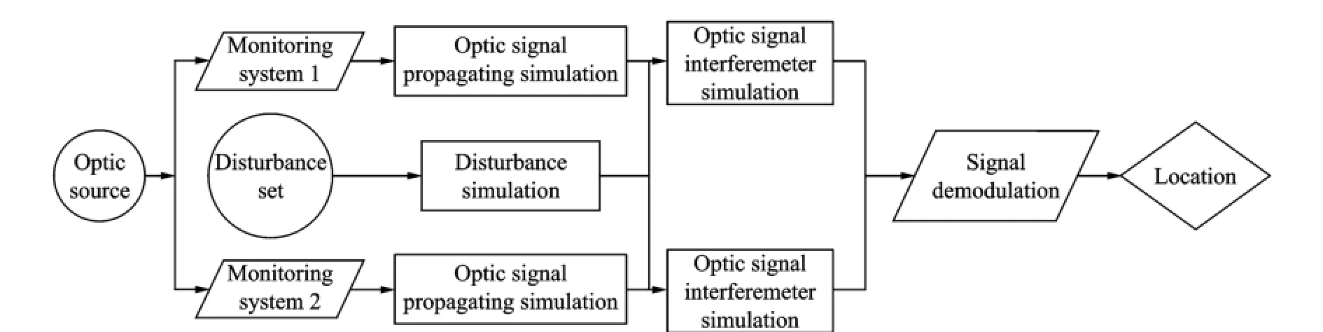
Eig.1 shows the monitoring system based on line-structure Sagnac interferometer with 3×3 coupler,where A is optic source;B1and B2are 3×3 couplers,C is the disturbance point;and D1to D4are 1×2 couplers;E is signal data processing part.The system includes two parts,the upper one is main system and the lower one is assistant system.Each of them has a delay optic fiber after the 3×3 coupler and a Earaday rotator mirror(ERM)in the end of the monitoring fiber,but the fiber length of the main system is the same as the detected pipeline,while the assistant system has another delay optic fiber between the monitoring fiber and ERM.As Eig.1 reveals,when the disturbance signal acts on the fiber,it modulates the phase of optic signal with clockwise and anticlockwise. Consider the interference condition that the optical propagation path has zero-difference and the phase modulation character of 3×3 coupler,two signals received by detector I21and detector I31
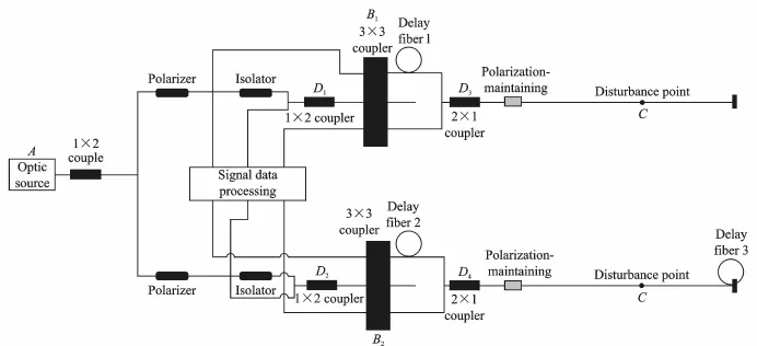
Eig.1 Security monitoring system based on line-structrue Sagnac interferometer with 3×3 coupler
are interferd and produced,respectively.After the signal data demodulation and calculation,the result will determine whether a disturbance action exists and which class it belongs to according to the signal frequency.
1.2 Working PrinciPle
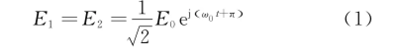
1.2.1 Optic signal propagation and interference The systems work as follows:The optic emit from the source will firstly enter two 2×2 couplers and be divided into two parts;one for the main system and the other for the assistant.The optic power is
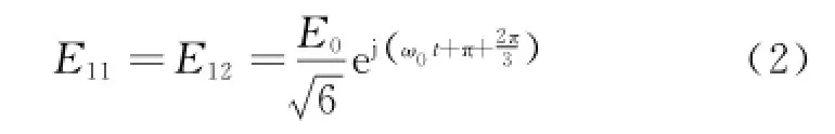
Take the main system as an example.The optic propagate through the 3×3 coupler and further signals are divided into three parts;two of them will propagate along clockwise and counterclockwise,then go back to the coupler and interfere.The 3×3 coupler is different from normal 1×2and 2×2 couplers.It may produce two interference signals detected by two various detectors. In ideal condition,the 3×3 coupler split ratio is 1∶1∶1 accurately,and each branch output power is the third of optic source.It should be mentioned that the phase bias of coupler is independent from other two ports and propagating direction is 120°.Then the optic power is
With two signals propagating around the monitoring fiber back to the couple,interference occurs.Eor the port I21,the two optic signal are
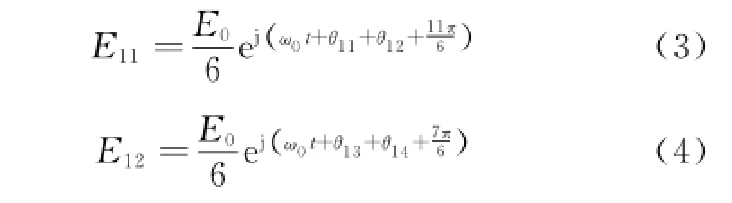
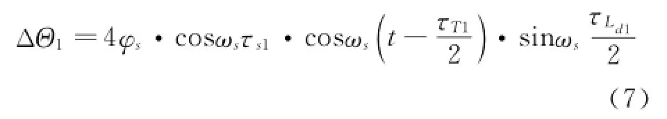
whereθ11andθ12are the phase changes produced by vibration acoustic signal when the optic signal propagates in clock wise passing the disturbance point twice;θ13andθ14the phase changes when the optic signal propagates in counterclockwise passing the disturbance point twice.Then the two interference signals are

whereΔΘ1is the phase difference between the signals of two directions demodulated by disturbance in main system
Demodulating the two interference signals can gain the main system demodulation signal Iz1
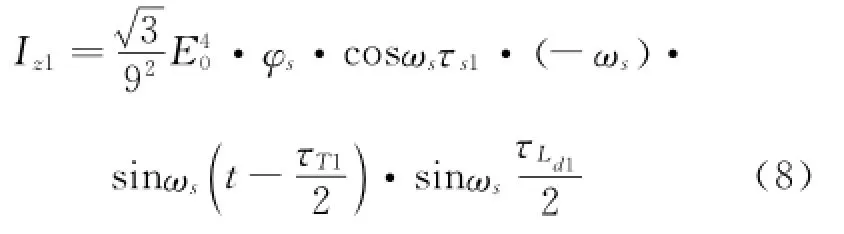
where E0is the optic signal amplitude;φsthe phase change amplitude;ωsthe disturbance signal angular frequency;τT1the time that the optic signal propagates through the whole circuit in main system;τs1the time that the optic signal propagates from the disturbance point to the middle of the main system circuit;τd1the time that the optic signal propagates through the delay fiber Ld1.
In the same way,the assistant system demodulation signal Iz2is
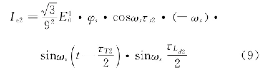
whereτT2is the time that the optic signal propagates through the whole circuit in the assistantsystem;τs2the time that the optic signal propagates from the disturbance point to the middle of the assistant system circuit;τd2the time that the optic signal propagates through the delay fiber Ld2.
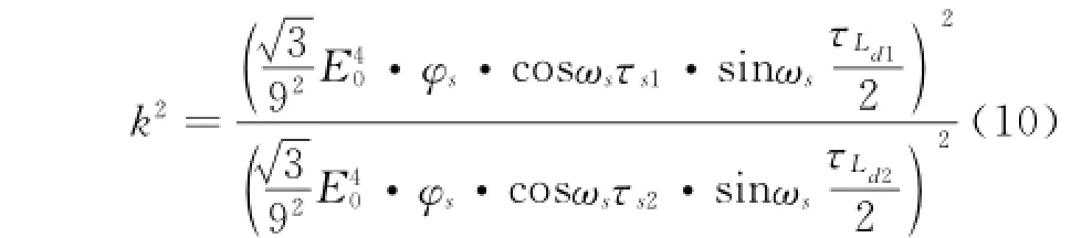
1.2.2 Disturbance source location
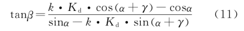
Disturbance location is an essential part of pipeline security monitoring.Traditional methods,including Zero frequency method[10,14-16]and Trap method,are not suitable for solving the problems of computation error and feasibility due to the effect and restriction of the frequency range and the demodulated signal phase amplitude. Using the demodulation results of the main system and the assistant system,it will get
Let
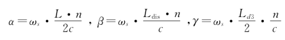
where L is the main system monitoring fiber length;Ldisthe distance from the main system start to the disturbance point in clockwise;Ld3the distance of the delay fiber in the end of the assistant system;n the fiber refractive index and c the velocity of light.
It will get
Then it becomes possible to compute the disturbance position in main system.
2 Simulation
SIMULINK is used to simulate the optic signal propagation and phase bias due to the disturbance,gain the interference result in ideal condition and calculate the disturbance position. Difference disturbance frequencies are set at 100,150,200,225,250,300,500 Hz and 1 k Hz.Assume delay fiber ratio Kdare 3,5,7,9,11,then the length of the assistant system delay fiber Ld2are 0.5,1,1.5,2 km.Disturbance position is set at 10 km from the start in clockwise of the main system,and the whole monitoring range is 25 km.Set sample time to be 0.000 01 s.The main system simulation procedure is shown in Eig.2.
Eig.2 Simulation flow diagram
Eig.3 shows the simulation results of position computation at 200 Hz.It is clear that when a certain value of the disturbance frequency is set,and the delay fiber ratio Kdincreases from 3 to 11,or the delay fiber length Ld2increases from 0.5 to 1 km,the data points discrete degree of location will decrease.
Eigs.4(a,b)are the relationships between Kdand the location average on the condition of Ld2=0.5 km and Ld2=1 km.Eigs.5(a,b)show the relationships between Kdand the absolute error of the location result.
When frequency changes from 100 Hz to 1 k Hz,the location averages have little error compared with the setting value in the same condition of Ld2and Kd,as shown in Eig.4 or Eig.5. Eigs.4,5 also show that if Kdis set in the range of 5 to 9,the result data will be close to the setting position and each absolute error will be very small,no more than 0.3%.Consider the powerloss,Ld2and Kdshould be set suitable for different frequences in engineering to ensure the position accuracy of the system.
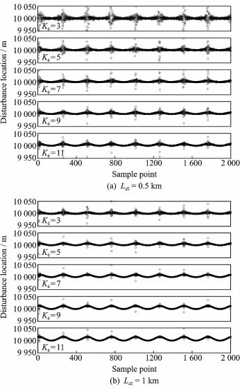
Eig.3 Location results of different delay fiber Ld2in 200 Hz
The disturbance location error is shown in Table 1.
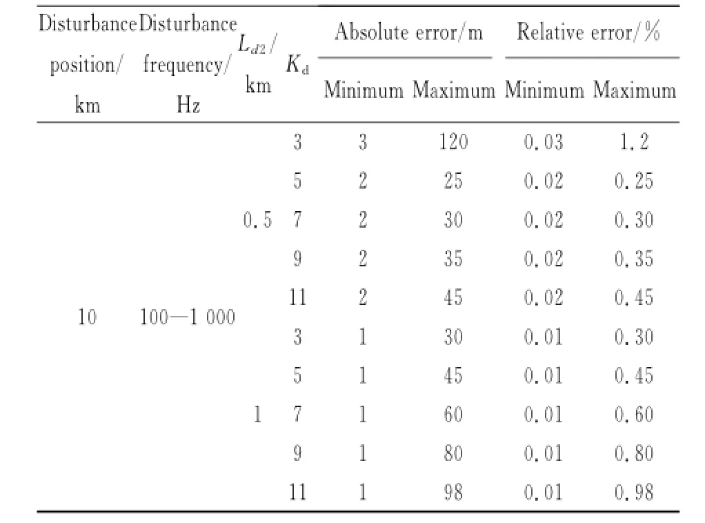
Table 1 Disturbance location error
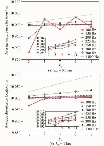
Eig.4 Relationship between location average result and Kd
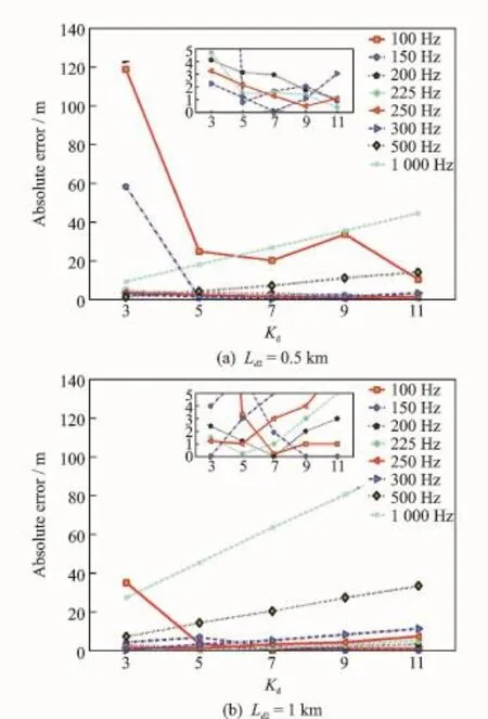
Eig.5 Relationship between absolute error of location average result and Kd
3 Conclusions
In this paper,a distributed fiber system is constructed based on line-structure Sagnac interferometer with 3×3 coupler to monitor the pipeline security.Theories of optic signal propagation and interference are analyzed.A method of location is put forward.And the possibility of threat action monitoring is realized.
A model based on MATLAB/SIMULINK is set up to simulate the optic signal propagation in the fiber and interference in coupler.Simulation results indicate that the system can monitor the frequency at least 100 Hz.The precision is high and absolute error is limited.
Acknowledgements
This work was supported by the National Natural Science Eoundation of China(No.51235001)and the Beijing Natural Science Eoundation(No.1122005).
[1] Zhang X J,Zhang G X,Ruan H.Distributed fiber optic sensor for oil pipeline leakage detection based on OTDR[J].Acta Optica Sinica,2008,37(12):2453-2457.(in Chinese)
[2] Mao J,Jiang H J,Li Y L,et al.Analysis study on the human factors of third partydamage to the oil and gas pipeline[J].Technology Supervision in Petroleum Industry,2010,26(1):12-15.
[3] Eemi T,David H.Distributed fiber optic sencors for pipeline protection[J].Jounal of Natrual Gas Science and Engineering,2009(1):134-143.
[4] Xu W Y,Zhang C X,Liang S,et al.Eiber-optic distributed sensor based on a sagnac interferometer with a time delay loop for detecting time-varying disturbance[J].Microwave and Optical Technology Letters,2009,51(11):2564-2567.
[5] Zeng K H,Zhang J Q,Wang E.Study and application on optical fiber pipeline security forewarning system[J].Computer Engineering and Design,2011,32(5):1862-1865,1701.(in Chinese)
[6] Giallorenzi T G,Bucaro J A,Dandridgeet A.Optical fiber sensor technology[J].IEEE J Quantum Electron,1982,QE-18:626-665.
[7] Hang L J,He C E,Wu B.Research on novel distributed optical fiber pipeline leakage detection technology and location method[J].Acta Optica Sinica,2008,28(1):123-127.(in Chinese)
[8] Zhang Y,Chen J M,Li G,et al.Location method of distributed fiber-optic perimeter security system based on mach-zehnder interferometer[J].Chinese Journal of Lasers,2012,39(6):1-4.(in Chinese)
[9] Eeng P P,He C E,Ruan L,et al,Research on security early warning system based on dual-Sagnac interferometer[J].Optic Technique,2013,39(6):488-495.(in Chinese)
[10]He C E,Zheng X Q,Luo J W,et al.Research on a pipeline leakage detection system and its stability based on depolarized sagac fiber intrferemeter[J]. Chinese Journal of Lasers,2012,39(2):0208002-1-0208002-5.(in Chinese)
[11]Gao C H,Yu J L,Liu J.Distribute optical fiber sensing system based on SOP time delay estimation[J].Journal of Optoelectronics·Laser,2012,23(1):28-34.
[12]Hu J C,Chen E C,Lin Z Q.A Brillouin optical time-domain reflectometer baesd distributed fiber optic instrusion sensor system[J].Journal of optoelectronics·Laser,2012,23(5):944-949.
[13]Wang W.Interferometric fiber gyroscope technology[M].Beijing:China Astronautic Publishing House,2010:45.(in Chinese)
[14]Hang L J,He C E,Wu B.Novel distributed optical fiber acoustic sensor array for leak detection[J].Optical Engineering,2008,47(5):054401-1-054401-6.(in Chinese)
[15]He C E,Zheng X Q,Luo J W,et al.Research on leak detection system for pipeline network based on distributed optical fiber sensing array technology[J]. Optical Technique,2011,37(1):1-4.(in Chinese)
[16]Hang L J,He C E,Wu B,et al.Detection technology of underwater pipelie leafage and its location method[J].Laser Technology,2011,35(3):376-379.(in Chinese)
(Executive editor:Zhang Bei)
TN247 Document code:A Article ID:1005-1120(2015)03-0312-06
*CorresPonding author:He Cunfu,Professor,E-mail:hecunfu@bjut.edu.cn.
How to cite this article:He Cunfu,Ruan Li,Wu Bin.Modeling and simulation of pipeline security monitoring system based on line-structure Sagnac interferometer with 3×3 coupler[J].Trans.Nanjing U.Aero.Astro.,2015,32(3):312-317.
http://dx.doi.org/10.16356/j.1005-1120.2015.03.312
(Received 15 January 2015;revised 16 April 2015;accepted 3 May 2015)
猜你喜欢
中国药房(2022年10期)2022-05-30
Chinese Physics B(2022年2期)2022-02-24
润·文摘(2021年7期)2021-08-23
恋爱婚姻家庭(2020年10期)2020-05-08
恋爱婚姻家庭(2020年4期)2020-05-03
华人时刊(2020年4期)2020-04-22
恋爱婚姻家庭(2017年10期)2017-09-20
职业技术(2012年6期)2012-08-31
情感读本·生命篇(2012年8期)2012-08-30
连环画报(2012年8期)2012-05-25
 Transactions of Nanjing University of Aeronautics and Astronautics2015年3期
- Transactions of Nanjing University of Aeronautics and Astronautics的其它文章
- Two-Dimensional Modal Curvature for Damage Detection in Plates
- Performance ImProvement Method of CFRP with Embedded OPtical Fiber
- MorPhological Undecimated Wavelet DecomPosition Fusion Algorithm and Its APPlication on Fault Feature Extraction of Hydraulic PumP
- Construction of Crack Perturbation Model and Forward Semi-analytical Model of Attached Eddy Current Sensor
- Resistance SPot Welding Method for Metal-Based Fiber Bragg Grating Sensors
- RelationshiP Between Corrosion Level of Steel Bar and Diameter of Corroded Sensing Steel Wire in Wireless Sensor