
Feasibility analysis ofWDM links for radar applications
2015-11-08 07:31:10MEENAFREDYFRANCISSARATHDIPINSRINIVAS
Defence Technology 2015年1期
D.MEENA*,FREDY FRANCIS,K.T.SARATH,E.DIPIN,T.SRINIVAS
aApplied Photonics Lab,ECE Department,Indian Institute of Science(IISc),Bangalore,India
bElectronics and Radar Development Establishment(LRDE),DRDO(Ministry of Defence),Bangalore,India
cModel Engineering College,Thrikkakara,Cochin,India
Received 9 May 2014;revised 27 August2014;accepted 10 September 2014 Available online 26 November 2014
Feasibility analysis ofWDM links for radar applications
D.MEENAa,b,*,FREDY FRANCISc,K.T.SARATHc,E.DIPINc,T.SRINIVASa
aApplied Photonics Lab,ECE Department,Indian Institute of Science(IISc),Bangalore,India
bElectronics and Radar Development Establishment(LRDE),DRDO(Ministry of Defence),Bangalore,India
cModel Engineering College,Thrikkakara,Cochin,India
Received 9 May 2014;revised 27 August2014;accepted 10 September 2014 Available online 26 November 2014
Active phased array antennasenhances the performanceofmodern radarsby usingmultiple low power transmit/receivemodules in placeof a high power transmitter in conventional radars.Fully distributed phased array radarsdemand the distribution of varioussignals in radio frequency(RF)and digital domain for real time operation.This is normally achieved through complex and bulky coaxial distribution networks.In this w ork,w e intend to tap the inherent advantagesof fiber linksw ith w avelength divisionmultiplexed(WDM)technology and a feasibility study to adapt these links for radar applications is carried out.This is done by analysing various parameters like amp litude,delay,frequency and phase variation response of various radarwaveforms overWDM links.Thisalso includesperformanceevaluation of non-linear frequencymodulation(NLFM)signals,known for better signal to noise ratio(SNR)to specific side lobe levels.NLFM waveforms are further analysed using pulse compression(PC)technique.Link evaluation isalso carried outusinga standard simulation environmentand is then experimentally verifiedwith otherwaveforms like RF continuouswave(CW),pulsed RF and digital signals.Synchronization signals are generated from this variable duty cycle digital signals during real time radar operation.During evaluation of digital signals,variable transient effects for differentduty cycles are observed from an amp lifier configuration.A suppressionmethod is proposed to elim inate this transienteffects.Further,the link delay response is investigated using different lengths of fiber spools.It can be inferred from the experimental results thatWDM links are capable of handling various signals significant to radar applications.
WDM;Radar;RF over fiber;EDFA transient;Delay;CW;Pulsed CW;NLFM
1.Introduction
Conventional radar signal distribution networks are designed w ith coaxial cable or space-feeds,which make the system bulky,complex,massive and inflexible[1,2].The inherentadvantagesof optical link is reduced size,weightand loss,low attenuation,immunity to electro-magnetic interference(EM I),and high bandw idth capacity[3].Along w ith the advancem ents in m icrowave photonic device technology,the possibility for distribution of signals in optical domain had been opened up.
During 1980's,the components capable of working in the microwave domain emerged.Pan[2]describesan optical link capable of working at 5 GHz.By 1984,a Ti:LiNbO3 Mach-Zehnder interferometer type external modulator capable of working at 17-GHz was developed towork in 830 nm[4].In 1987,Stephensetal.[5]described a complete radio over fiber(RoF)link while com paring the performances of directmodulation and external modulation using loss,SNR(signal to noise ratio),linearity,etc.,as the parameters for 4.1-4.7 GHz and 2.0-12.0 GHz.In 1988,the applications of radar X-band signal in fiberoptic linkswere studied by a team in Malibu[6]. They were primarily interested in providing RF delay using fiber optic link for application in radar phase noise testsetandradar repeater test.Link characterisation was also done for AM and FM modulations in direct and externalmodulations using 1300 nm InGaAs laser.Cox et al.[7]described an analytical lumped-element small-signalmodel of directly and externallymodulated analog fiberoptic link.The designed link was described to be superior to others in providing a maximum bandw idth of 22MHz for externallymodulated link(11 dB transducer gain,6 dB noise figure)and 1 GHz bandw idth for directly modulated link(-14 dB transducer gain,33 dB noise margin).They theoretically proved that the efficiency of externally modulated M ach-Zehnder modulator(MZM)operated at moderate bandw idth w ith high optical power is several times higher than that of directmodulation. Due to the versatility and practicality of optical links,soon resultswereavailable in introducing true timedelays in phased array antennas[8].The paper also provides a method to overcome beam squinting and describes the use of fiber delay loops in introducing a phase delay in m icrowave regime,which is expected to have a great impact on phased array antenna construction.It isonly amatter of time that theoptical system finds its way into the avionics industry,where light weight and immunity to EM I are highly desirable.Slaveski et al.[9]discussed the transm ission of analog AM and FM signals over a WDM link along w ith FSK digitalmodulated signalbetween antennasand on-board avionic equipment.The resultswere prom ising w ith insertion loss of-55 dB,carrier to noise ratio(CNR)and SNR of more than 40 dB,total harmonic distortion(THD)of less than 7%and BER ofmore than 1.85e-07.This proves that the link worksasefficiently as coaxial cable in antenna-cockpit link w ith the additional benefits ofWDM optical systems.
In 2007,the researchers at Thales reported about the feasibility study of using RF photonics for radar applications[1],which proved that the commercial optical components are matured enough to carry radar signals.They tested the linkw ith local oscillator(LO)and pulsed RF signalsand,they designed the directmodulated narrow band and wide band links using active and reactive matching networks.In this work they brought the results fordirectmodulated and externalmodulated link performance in termsof frequency response,noise spectral density curve vs RF frequency curve.They used CWDM(coarse WDM)optical link as part of a demonstrator architecture.The experiments prove w ithout doubt that the optical com ponents havem atured enough to be used in m ilitary.
Ballal et al.performed a comparative study of analog and digital RoF links in terms of their merits and demerits[10]. They mentioned that various disadvantages,such as nonlinearity and chromatic dispersion,of analog RoF link can bemitigated by use of digital RoF link.Bit error rate(BER)and SNR for various inputschemes,such asBPSK,QPSK and 16 QAM,were analysed for analog and digital links,and their comparison was presented.Digital RoF link shows improved performance in terms of BER parameters.
More studies followed as in Ref.[11],which characterized a direct modulated optical link for X-Band chirp modulated radar signal.Further,the link was inserted w ithin Salex-Galileo LPI radar and the results were obtained w ithout any performance degradation.Yao[12]described the possibility of RoF distribution along w ith photonic true time delay beam forming.Ghelfi et al.[13]proposed a fully photonics-based coherent radar,exploring usage of optical components to the maximum extent,rather than using photonic componentsonly for distribution of signals.This is achieved by generating of stable radio frequency signalshaving arbitrary waveformsand detecting the signals by direct digitization w ithout downconversion.Xu et al.[14]described about the advantage of using photonic techniques to generate and distribute the m icrowave signals and also addressed various challenges in system realization.
In thispaper,webring outothermeasurementresultswithRF signals in termsof amplitude,delay,frequency and phasevariationsoccurring inWDM links.As thephased array antennahas large number of transmit/receivemodules,a splitterw ith large splitting ratio isused to distribute thesignals.To compensate for thissplitter loss,anopticalamplifier is required in theWDM link configuration.Modern multifunction radar uses variable duty cycle signals for itsnormalmode of operation.Wealso analyse the effectsof digital signals in amplifier basedWDM linksand observed the transient effects w ith variable duty cycle digital signals.We also discuss a transient suppressionmethod for the transm ission ofvariableduty cycledigitalsignalsover fiber links. During experimentalevaluation,the differentsignalssignificant to radar,such asCW,pulsed CW and NLFM waveforms,are fed through theWDM link.Themeasurementsare repeatedbyusing differentfiberspool lengthstomeasuresignaldelay,which tallies w ith the mathematically computed signal delay value.Even though the experiments are carried out for measurement of various parameters,we mainly focus on amplitude and delay variationsw ithin the scope of this paper.Butsome of themeasurement results,such as frequency vs.time and phase vs.time plots,are considered to ensure the link adaptability to different waveforms.
2.Experiment
In a radar system,the echo signals are converted to intermediate frequency(IF)signals during receive operation.This down conversion process requires different local oscillator(LO)signals at each receiver module.Additionally,active phased array requires the distribution of digital signalsof a bitrate<1 M bit/s for control and m onitoring purpose.A phase reference signal,having a stringent inter-element phase error requirement,isalso presented to ensuresynchronousoperation amongmultiple transmit/receivemodules.
Fig.1 showsan experimental setup.RF signal isexternally modulated using a CW laser operating at1550 nm and Mach-Zehndermodulator(MZM),while the digitalsignal isdirectly modulated using a DFB laser.
The digital signals in differential format are normally used in a radar system to reduce the commonmode noise occurring in the transm ission line.Therefore,in order to test this kind of signal,a single ended digital signal is first converted to differential signal format using a RS422 transm itter module.A differential optical transmittermodule then directlymodulatesa DFB laser to produce themodulated optical output.These signals are then multiplexed using a 2:1 arrayed waveguide grating(AWG)typemultiplexer.Finally at the receiver stage,the signals are demultiplexed and retrieved using respective detector modules.The different parameters associated with WDM link are listed in Table 1.
Fig.2 shows an experimental set-up.A radar transm itter operating in 2-4 GHz is used as the RF signal source.A digital signal sim ilar to synchronization signal in a real time radar system is generated using the digital signal source.The spectra of differentwaveforms are observed using a real time spectrum analyser(RTSA).This configuration helped in measuring the attenuation valuesassociated w ith transmission of RF signals over a WDM link.The delay occurring in the link wasmeasured using a digital storage oscilloscope(DSO). The experiment was repeated using different kinds of radar waveforms like continuous wave(CW),pulsed continuous wave and NLFM waveforms.Other RTSA plots used for the m easurement include normal spectral plot,digital phosphor technology(DPX)[15]waveforms,amp litude vs.time(envelope)p lot,frequency vs.time p lot,and phase vs.time plot.

Fig.1.Block diagram ofWDM link-experimental set-up.
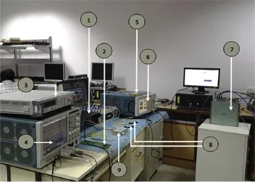
Fig.2.Measurementalset-up.1-differentialsignal-opticalsignal converter;2-differentialsignalgenerator;3-digitalsignalsource;4-DSO;5-RF over fiber receiver;6-spectrum analyzer;7-radar transmitter;8-mux/demux;9-RFover fiber transm itter.

Fig.3.Waveform spectrum of continuous input signal.
Table 1 Parameters of optical link.
3.Resu lts
A RF signal w ith a frequency of 3.1 GHz and amplitude -12.43 dBm is used as the source signal in WDM link for measuring CW-RFwaveform parameters.Figs.3 and 4 show thewaveform spectra for a continuouswave input and output signals,respectively.It can be observed from Fig.3 that the input spectra is reproduced at the receiver end,retaining the critical central frequency and bandw idth criteria.As the critical waveform parameters are retained at the receiver end,we now focus on other parameters like amp litude,delay,frequency and phase for furtheranalysis.A few of theexperiment results are included in the follow ing sections.
Figs.5 and 6 show the DPX waveforms of pulsed continuouswave signal at link inputand output.Again output signal is observed w ith a constant attenuation of 27.52 dB w ithout significant distortion.
Table 2 summarizes the measured results of different test cases.It should be noted that the link incurred a net loss of approxim ately 27 dB,which is independent of waveforms.
It can be observed thatboth the optical signals(at1310 and 1550 nm)were continuously present throughout the experiment,confirming that there isno crosstalk between the signals in WDM FOL[9].The measurement results of an intensity modulation-direct detection,linearly frequency-modulated(LFM)signal and X-band radar signal over a single analog link were discussed in Ref.[11].But this paper dealsw ith anexternally modulated WDM link using other waveforms like CW,pulsed CW and NLFM radar signals.
A fter the evaluation of amp litude variation w ith various radar waveforms,the link is evaluated further for other parameters like phase,frequency and delay.Fig.7 shows the phase variation of continuous signal(3.1 GHz)at link output w ith respect to time.It can be observed that the linear phase relation ismaintained while the signal is transm itted through the link.
NLFM waveformsare used inmodern radarsow ing to their improved security and better side lobe reduction[16].
Fig.8 shows output NLFM waveform.It can be seen that the envelope is faithfully reproduced.
Figs.9 and 10 show the frequency vs.timeofNLFM inputand outputsignals.Thevariation in frequencywith respectto timecan be observed to be nonlinear,and controlled by the non-linear coefficientsused in thegeneration ofwaveform.Non-linear frequency variation of the inputcan be seen to be faithfully reproduced at the link output.But spectrum output alone cannot represent the side lobe level requirements.Therefore a pulse compression(PC)technique isperformed on the captured samples Iand Q(using RTSA)ofWDM outputsignal.
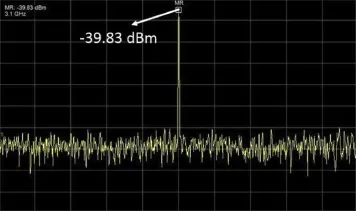
Fig.4.Waveform spectrum of continuous output signal.

Fig.6.DPX waveform of pulsed output signal.
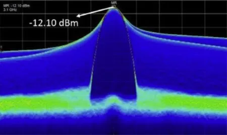
Fig.5.DPX waveform of pulsed input signal.

Table 2 Measured values.
3.1.Pulse compression of NLFM waveform
During measurement of NLFM waveform,the real time samples Iand Q(in phase,quadrature)of output signal are captured using RTSA and processed w ith necessary NLFM coefficients to obtain a pulse compressed output of both the WDM input and the output signals.Figs.11 and 12 show the pulse com pressed results(red(in the web version))of input and output signals along w ith corresponding envelope of NLFM signals(green(in the web version)).Figs.11 and 12 show the expanded view of a single output pulse,whereas the actual transm it signal is a burst of a specific number of continuous pulses.A particular radar application requires a side lobe level of approximately 20 dB to attain a certain level of radar performance.But the resultantoutputsignal side lobe level isapproximately 25 dB(Fig.12),satisfying the required performance level.
3.2.Simulation results
The amplitude variation for the sameWDM linkmodel is evaluated in a standard simulation environment(OptiSystem)to substantiate the experimental results(Fig.13).A RF signal in GHz range and a digital signal in MHz range are used as input signals for evaluation purpose.The RF signal is externally modulated using a Mach-Zehnder modulator.Since OptiSystem does notsupport comp lex waveform s like NLFM,LFM,etc.,amathematicalmodelof M ach-Zehndermodulator,which supports the generation and modulation of signalsw ith various controlling parameters,was developed in MATLAB.This model is used as a co-simulation component in Opti-System environment along w ith other components for link evaluation.The modulation part of the sam e component is used for evaluation of CW RF signal.The obtained results show a link loss of~27 dB,tallying w ith the experimental results(refer Table 3)for inputof-12.182 dBm and outputof -39.479 dBm.
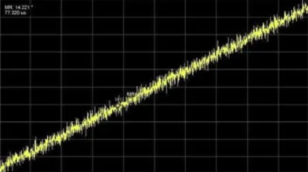
Fig.7.Phase vs.time for outputwaveform of CW radar signal.

Fig.8.Amplitude vs.time for outputwaveform of NLFM signal.
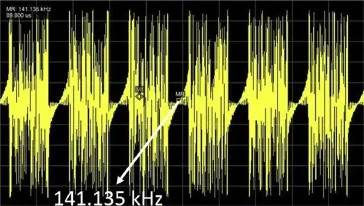
Fig.9.Frequency vs.time for inputwaveform of NLFM signal.
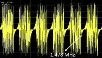
Fig.10.Frequency vs.time for outputwaveform of NLFM signal.

Fig.11.Envelope of inputRFand pulse compressed output-expanded view.

Fig.12.Envelope ofoutputRFand pulse compressed output-expanded view.
3.3.Delaymeasurement for WDM link
During the measurement of delay,a pulsed RF signal,(pulsew idth of 1msand period of 10ms)is divided into two by using a 2-way power divider and given simultaneously to DSO and WDM input.The WDM output is fed to another DSO channel.The cables used were calibrated prior to experiment.
Figs.14 and 15 show the DSO outputs for 500 m and 1000 m long optical fiber links,respectively.The pulses are delayed by 2.56 and 5 ms for 500 m and 1000 m long links,respectively.
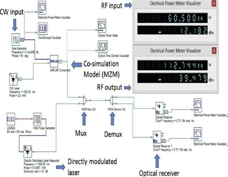
Fig.13.WDM co-simulation model in standard optical simulation software environment.
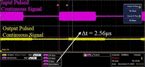
Fig.14.Delay of pulsed RF signalw ith fiber length of 500 m.
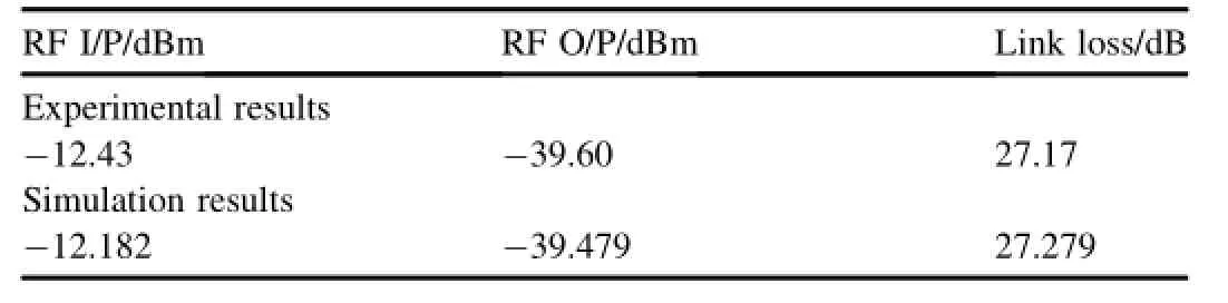
Table 3 Link loss.
4.Discussion on results
4.1.Amplitude measurement
From Table 2,it isevident that,for the differentkindsof RF signals,theWDM link introduced an attenuation of approximately 27 dB,which can be attributed to the losses at various components,as given in Table 4.This parameter is very important due to the fact that any variation in signal parameters of the output signal affect the performance of the radar when WDM links are used as a part of the distribution networks.Since this attenuation value is determ inistic,it can be compensated either by RF or optical amplifiers as per the requirements.
The total lossof 27 dB observed w ith analogWDM links is found to be in consistence w ith the results in Ref.[7].Even though the directmodulation is cheaper,simpler and offers a higher conversion efficiency,it can cause frequency modulation at its optical output due to themodulation of refractive index of laser cavity by themodulating signal.This spurious frequencymodulation distorts the frequencymodulation of the signal[1,11].Themeasured results show s that the externallymodulated analog linksare free from these distortions,asalso shown for FM and AM analog links[9]w ith external modulation.
4.2.Delaymeasurement
The delay incurred in an optical link is primary attributed to the refractive index and length of fiber.Component propagation delaysare smalland hence neglected.A singlemode fiber w ith an effective refractive index of 1.5 and carrying a 1550 nm optical signal isused formeasurement.Theexpected delay is

where l is the length of fiber;v=c/n is the speed of light in optical fiber;c is the speed of light in vacuum(3×10⁸m/s);and n is the effective refractive index of optical fiber. Therefore,
1)Theoretical delay for 500m long fiber is around 2.5ms.
2)Theoretical delay for 1000 m long fiber is around 5 ms.
These values are also found to be comparable to the measured results,asshown in Figs.13 and 14 and summarized in Table 5.The delay parameter is of prim ary importance in radar systems,and any delay could be taken as Doppler shift. As the optical delay is determ inistic,itcan be compensated in an efficientmanner.
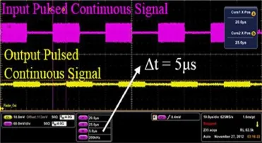
Fig.15.Delay of pulsed RF signalwith fiber length of 1000m.

Fig.16.Schematic diagram of experimental set-up used for EDFA transient effectmeasurement.

Table 4 Loss budgetofWDM link.

Table 5 Delays for various test cases.
5.Digital signal:m easured resu lts and discussion
Digital signals are used in radar systems for control and monitoring purpose.These signalsmay vary in their bit-rate and duty cycle.The measured result of direct modulated digital signal(Fig.1)was found to be sim ilar to that of the RF signal,where the insertion loss associated w ith RoF transm it/ receivem odules were replaced w ith the conversion losses of DFB laser and detector.
Signal distribution in a large array demands the use of optical amplifiers to compensate these losses incurred for splitting a signal to a large number of transmit/receivemodules.These losses increases w ith splitting ratio.The splitting loss can be computed as10 log N,where N being the splitting ratio,i.e.,1:64,can cause a signal attenuation of 18 dB along the link.Thus optical amplifiers are used to boost the signal level.Er-doped fiber am plifiers(EDFA)is comm only used for this purpose.But itwasobserved that the digital signals suffer from transient effectw ith saturated EDFA as reported in Refs.[17,18].Additional linksmay require gain flattening circuits based on the application.Singh etal.[19]presented a Raman-EDFA hybrid optical amplifier configuration.This amplifier configuration provides a flat gain of greater than 10 dB w ithout any gain flattening circuits.But our work focus on variable transients observed with different duty cycle signals. This can degrade the digital signal transmission through fiber link.
A configuration shown in Fig.16 is used to analyse the transient effect while amplifying the digital signals in the optical links.A 1530 nm laser diode(1mW)ismodulated by a 2 kHz digital signal.Except for EDFA,thisset-up isconsisted by the components available as parts of a commercialWDM test unit,which is capable of generating variable duty cycle pulse signals.The laser output is amplified using an EDFA operating in the saturation region w ith a pump power of 30mW(980 nm).EDFA used is10m in length,Er lifetime is10 ms,Er ion density is 2×1025m-3,numerical aperture is 0.24,core radius is 2.2μm,and Er doping radius is 2.2μm. The output is then passed on to aphoto detectorofWDM unit,and the electrical output is observed using a DSO.
Fig.17 shows the transient effect observed in the output digital signal.The spikes occurring at the output pulses are due to transient effects.As the digital signals used in radar system are primarily used for control and synchronizing,any change in signal characteristics can seriously degrade the beam formation and radar operation.
Additionally,the pulsed signals used for synchronization are produced based on a transmitwaveforms that are random in nature and have different duty cycles.The transient effects for differentduty cyclesare simulated and isshown in Fig.18. It can be observed that the transient peaksand slope decrease w ith the increase in duty cycle,which can be explained to be due to greater time available for EDFA gain recovery.These transients are follow ing an exponential curve mentioned in Ref.[13].The m athem atical derivation of the sam e is not included in this paper.
Fig.19 shows the measured transient result for a digital signalw ith pulsewidth of 300μs and period of 500μs.
In addition,itwasobserved that the effectof transientscan be reduced by multiplexing an additional signal,w ith a complementary pulse,along the link w ith a nearby wavelength(Fig.20).

Fig.17.Measured transients for 2 kHz pulsed signal-input(yellow)and output(blue).
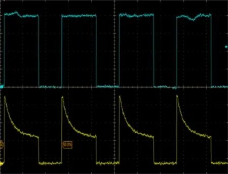
Fig.18.EDFA Transients w ith 10,20 and 50%duty cycle(2 KHz pulsed signals,pump power at 60 mW).
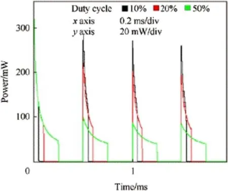
Fig.19.Transient effect in a digital signal of duty cycle 60%input(blue),output(yellow).
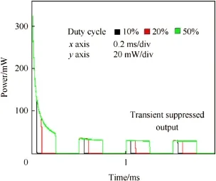
Fig.20.Transient suppressed output.
6.Conclusions
WDM-based optical networks are preferred over the conventional signal distribution schemes ow ing to their physical compactness,low loss,light weight and immunity to EM I. Conventional signal distribution network adds considerably to the system complexity and bulkiness of the active phased arrays.Itmakes the system massive and demandshigh capacity drive mechanisms for rotary joints.This paper explored the feasibility of using optical WDM link for distribution of different types of RF and digital signals,hence making the system light and agile.The RF signals like CW,pulsed CW,and NLFM waveforms generated from a radar transm itterwas used for experimental measurements.The results wereobserved w ith a finite attenuation due to various com ponent losses incurred in the link,irrespectiveof the inputsignalused. The amplitude variations for continuous wave signals were verified using the simulation results.Since the link loss is fixed,fora particularnetwork itcan easily be compensated by using the amplifiers in the electrical or optical domain.
The experimental results of NLFM waveform was further verified for side lobe requirementsby using pulse compression(PC)techniques.The experiments were also repeated with various fiber spools.The results were observed w ith a delay proportional to the length of the fiber spool.Therefore,delay and attenuation,being determ inistic parameters,can be compensated based on the application requirements.
Further,the paper also discussed about the transienteffects associated w ith digital signals of variable duty cycle.This transient effects can be reduced by adding an additional complementary signal in the WDM link.
This kind of optical distribution helps in the generation of radar signals outside antenna arrays and their distribution through optical rotary joints.Thus it helps in providing a solution free from EM I/EMC related issues.
[1]Garenaux K,Merlet T,AlouiniM,Lopez J,VodjdaniN,Boula-Picard R,et al.Recent breakthroughs in RF photonics for radar systems.Aerosp Electron Syst M ag IEEE 2007;22(2):3-8.
[2]Pan J.5-GHzw ideband fiber-optic link.OSATechnicalDigestSeriesOpt Fiber Commun 1983.paper TuK2.
[3]Capmany Jos'e,Dalma Novak.M icrowave photonics combines two worlds.Nat Photonics 2007;1(6):319-30.
[4]Gee CM,Thurmond GD,Yen HW.17-GHz bandw idth electro-optic modulator.Appl Phys Lett1983;43(11):998-1000.
[5]StephensW illiam E,Joseph Thomas R.System characteristics of direct modulated and externallymodulated RF fiber-optic links.Light Technol 1987;5(3):380-7.
[6]Gee CM,Newberg IL,Thurmond GD,Yen HW.X-Bana Rf fiber optic links.In:Cambridge Symposium-Fiber/LASE'86.International Society for Opticsand Photonics;1987.p.64-8.
[7]Cox III,Charles H,Betts Gary,Johnson Leonard M.An analytic and experimental comparison of direct and externalmodulation in analog fiber-optic links.M icrow Theory Tech IEEE Trans 1990;38(5):501-9.
[8]Frigyes Istvan,Seeds AJ.Optically generated true-time delay in phasedarray antennas.M icrow Theory Tech IEEE Trans1995;43(9):2378-86.
[9]Slaveski Filip,Sluss James,Atiquzzaman Mohammed,Nguyen Hung,Ngo Duc.Transm ission of RF signals over optical fiber for avionics applications.In:21st Digital avionics systems Conference,2002.Proceedings.IEEE,vol.1;2002.4D2-1.
[10]BallalBeenaR,NemaShikha.Performancecomparisonofanaloganddigital radio over fiber link.Int JComput SciEng Technol(IJCSET)2012;3:6.
[11]Pardini Rossano,Bruno Umberto,Izzo Roberto.Characterization of a fiber-optic directmodulation analog linkw ith chirp radarsignals.In:Radar Conference,2009.EuRAD 2009.European,IEEE;2009.p.449-52.
[12]Yao JP.A tutorial on m icrowave photonics.IEEE Photonics Soc New sl 2012;26(3):5-12.
[13]Ghelfi Paolo,Laghezza Francesco,Scotti Filippo,Serafino Giovanni,Capria Amerigo,Pinna Sergio,et al.A fully photonics-based coherent radar system.Nature 2014;507(7492):341-5.
[14]Xu K,Wang RX,Dai YT,Yin FF,Li JQ,Ji YF,et al.M icrowave photonics:radio-over-fiber links,systems,and applications[Invited].Photonics Res 2014;2(4):B54-63.
[15]http://www2.tek.com/cmsw pt/tidetails.lotr?ct=TI&cs=pri&ci=4540[Retrieved on 30.08.2013].
[16]Vizitiu Iulian-Constantin.Sidelobe reduction in the pulse-compression radarusing synthesis of NLFM laws.Int JAntennas Propag 2013:2013.[17]Kuroda Keiji,Yoshikuni Yuzo.Single wavelength pump-probe technique to measure population recovery in a continuously pumped fiber amplifier.Opt Commun 2013;300:96-9.
[18]Kuroda Keiji,Sasahira Kohnosuke,Yoshikuni Yuzo.Gain saturation of a CW-pumped erbium-doped fiber amplifier for nanosecond pulses.Opt Fiber Technol 2012;18(1):44-6.
[19]Singh Sim ranjit,Kaler RS.Flat-gain L-band Raman-EDFA hybrid optical amplifier for densewavelength divisionmultiplexed system.Photonics Technol Lett IEEE 2013;25(3):250-2.
.Electronicsand Radar Development Establishment(LRDE),DRDO(M inistry of Defence),Bangalore,India.
E-mail addresses:dmeenasatish@gmail.com,meenad@ece.iisc.ernet.in(D.MEENA).
Peer review under responsibility of China Ordnance Society.
http://dx.doi.org/10.1016/j.dt.2014.09.002
2214-9147/Copyright©2014,China Ordnance Society.Production and hosting by Elsevier B.V.All rights reserved.
Copyright©2014,China Ordnance Society.Production and hosting by Elsevier B.V.A ll rights reserved.

- Defence Technology的其它文章
- Prediction of flow stress of 7017 alum inium alloy under high strain rate compression at elevated temperatures
- Semi-analyticalmethod for calculating aeroelastic effect of profiled rod flying at high velocity
- Experimental investigation of Ti-6Al-4V titanium alloy and 304L stainless steel friction welded w ith copper interlayer
- Study of high-speed interaction processesbetween fluoropolymerprojectiles and alum inum-based targets
- M icrostructure and corrosion behaviour of gas tungsten arc welds of maraging steel
- Performance characterization of Ni60-WC coating on steel processed w ith supersonic laser deposition