
Experimental investigation of Ti-6Al-4V titanium alloy and 304L stainless steel friction welded w ith copper interlayer
2015-11-08 07:31:08KUMARBALASUBRAMANIAN
Defence Technology 2015年1期
R.KUMAR*,M.BALASUBRAMANIAN
aMechanical Engineering,SKP Institute of Technology,Tiruvannamalai,Tamilnadu 606611,India
bRMK College of Engineering and Technology,Tiruvallur,Tamilnadu 601206,India
Received 3 August2014;revised 28 September 2014;accepted 17 October 2014 Available online 5 January 2015
Experimental investigation of Ti-6Al-4V titanium alloy and 304L stainless steel friction welded w ith copper interlayer
R.KUMARa,*,M.BALASUBRAMANIANb
aMechanical Engineering,SKP Institute of Technology,Tiruvannamalai,Tamilnadu 606611,India
bRMK College of Engineering and Technology,Tiruvallur,Tamilnadu 601206,India
Received 3 August2014;revised 28 September 2014;accepted 17 October 2014 Available online 5 January 2015
The basic principle of friction welding is intermetallic bonding at the stage of super plasticity attained w ith self-generating heat due to friction and finishing atupset pressure.Now the dissimilarmetal joints are especially popular in defense,aerospace,automobile,bio-medical,refinery and nuclear engineerings.In friction welding,some special alloys w ith dual phase are not joined successfully due to poor bonding strength.The alloy surfaces after bonding also havemetallurgical changes in the line of interfacing.The reported research work in this area is scanty.Although the sound weld zone of directbonding between Ti-6A l-4V and SS304L was obtained thoughmany trials,the jointwasnot successful.In this paper,the friction welding characteristics between Ti-6A l-4V and SS304L into which pure oxygen free copper(OFC)was introduced as interlayerwere investigated.Box-Behnken design was used tominim ize the number of experiments to be performed.Theweld jointwas analyzed for itsmechanical strength.The highest tensile strength betw een Ti-6A l-4V and SS304L between which pure copperw as used as insertmetalwasacquired.M icro-structuralanalysis and elementalanalysiswere carried outby EDS,and the formation of intermetallic compound at the interfacewas identified by XRD analysis.
Friction welding;Ti-6Al-4V;SS304L;Oxygen free copper;Interlayer;M icrostructure;Interface
1.Introduction
Friction welding(FW)isa solid-state joining technique,by which significant heat is generated on the faying surfaces of two components under a certain combination of pressure,time,speed and surface roughness of weld face.Heat is generated by the friction which softens the materials to be joined before deforming them plastically.After an interfacial region is plasticized,a metallurgical bond is finally formed under the action of axial forging force instantly due to relative movement.In thisprocess,the plastic deformation in theweld zone results in grain refinement,in a flow line orientation the impurities are pumped out to the outer region and thewhole process is finished in few seconds[1].Ti alloy is m ore expensive than othermaterials,but due to its higher strength and bettermechanical properties it has attracted attention and introduction of Ti alloy has spurred interest.The forged aluminum used to manufacture the commander's hatch in a fighting vehicle hasbeen replaced with forged titanium w ith a weight saving of 35%and w ith a great improvement of ballistic protection.Other components,such as torsion bar,lightweight armor,road arm,support arm,road wheel,and gear housing,in the battle tank were made of high-strength beta titanium alloys by friction welding[2].Tihelium vessel m ust be joined to a stainless steel in cryogenic p lumbing system[3].Tiand stainless steelhave been w idely app lied for nuclear industry pipe lines and accessories in oil rig.Steel--titanium coupling is used in biomedical applications like dental implants and articulation replacement.Ti alloy andstainless steel are used to weld aircraft engine blades(titanium),discs(stainless steel),and aero engine casing w ith high service temperature[4,5].
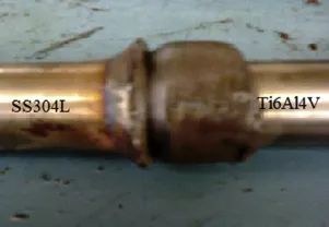
Fig.1.Ti-6AL-4V and SS 304L w ithout interlayer.
Fig.2.Failed joint w ithout interlayer subjected to drop test.
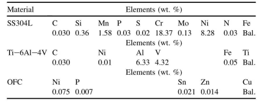
Table 1 Chem ical composition ofmaterials under study.

Table 2 Mechanical properties of basemetal.
In advanced engineering and technology the process steps and processmaterialsaremore efficient tomeet the industrial demandsw ith the optimized condition[6,7].Friction welding is vastly attractive for joining difficult-to-weld and high performance dissimilar alloys.Tialloy and stainless steelw ithout interlayerwas initially fabricated at constant speed,and other FW parameters were varied.Even though the findings are m oderate in mechanical and metallurgical evaluation,the failure happened in theweld zone due to insufficientheating in stainless steel side and the formation ofmartensitic structure(Fig.1 and Fig.2)[8].Ti-6Al-4V w ith interlayerof Ni,WC,Nb in the form of foilwas studied.This joint performswell in the case ofmultiple layer ofmaterial foils and fails when a single foil is used,as it is peeled from the interfacial region due to high friction pressure[9].To overcome thisdifficulty,a pure titanium and stainless steel jointwas attempted w ith an interlayer of copper and nickel which yielded good bonding strength.The same m aterials were investigated w ith the intermediatematerials of nickel,vanadium and tantalum in between the dissim ilar base metals and nickel retained the bonding than othermaterials[10,11].Maraging steel friction welded w ith low alloy steel by using solid nickel as an interlayer after post weld heat treatment was evaluated by mechanicalandmetallurgicalanalysis.In this processNiacted as an effective diffusion barrier between the parentmaterials and avoided carbonmigration inweld region[12].The friction welding of incompatible materials and the feasibility of the methodwere experimented fordifferentmaterialcombinations of brass/copper,bronze/steel and titanium/nickelw ith suitable thirdmetal interlayer.With careful experimental analysis,the joint efficiency was increased by 40%[13,14].The effects of frictionwelding parametersand heat treatmenton nickelalloy jointswere established and the best resultswere obtained[15]. Friction welding of austenitic stainless steel and copper was experimentally investigated w ith various parameters through Taguchiorthogonalarray,and theoutcomeswereevaluated for its joint strength.Itconcluded thatmore friction pressurew ith low upset pressure increases the tensile strength[16].Friction welding of pure titanium and pure copperwasestablished and the performancesof jointswere analyzed.Due to higher purity of copper,the bonding strength in the faying surfaces was tremendously increased by selecting the optimum parameter and fine surface finish[17].TiAl alloy casting and AISI4140 commercial steel rod were fabricated by friction welding w ith pure copper as intermediatematerial.From the evaluations it was found that the directbonding let to crack through interface due to brittle reaction;but in caseof copper interlayer the joint was free from defects.Considering the above literature studies,Ti-6Al-4V and SS304L were friction welded w ith oxygen-free copper(OFC)as an interlayer.The reason for choosing OFC as an interlayermaterial is that it has higher ductility,higher linear expansion coefficient and minimizes the residual stresses near the bonding surfaces.The heataffected zone(HAZ)on stainless steel side isminimized by the reduction of brittlem artensitic phase during thermal cycle,show ing higher weldability of stainless steel and Ti alloy. Moreover,the pure copper has high thermal conductivity;it can transfer theweld heat from the interface.It canminimize thew idth of heat-affected zoneon thestainlesssteelside,suchas brittle martensite phase formation during the welding thermal cycle[18].

Fig.3.Frictionwelding setup.
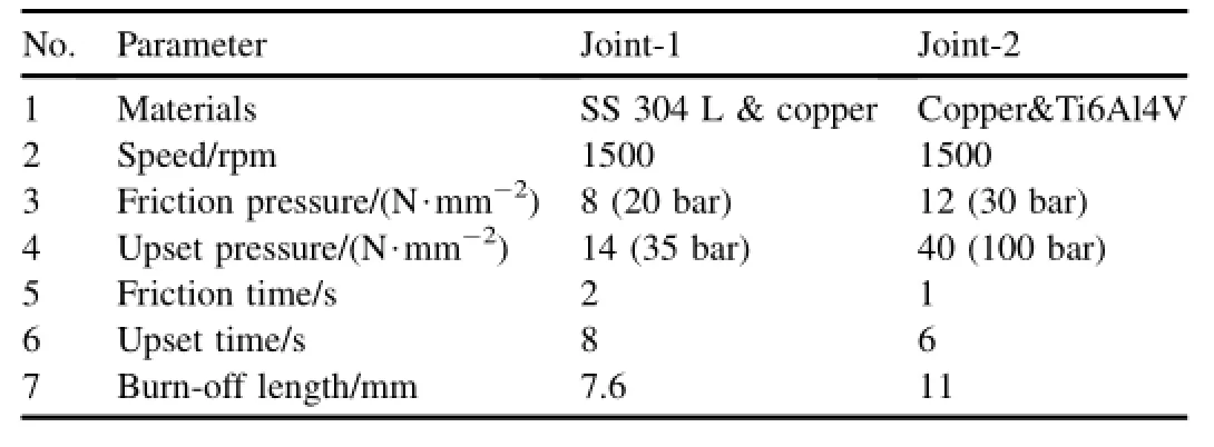
Table 3 Important friction welding parameters.

Table 4 Variable parameters for Joint-2.
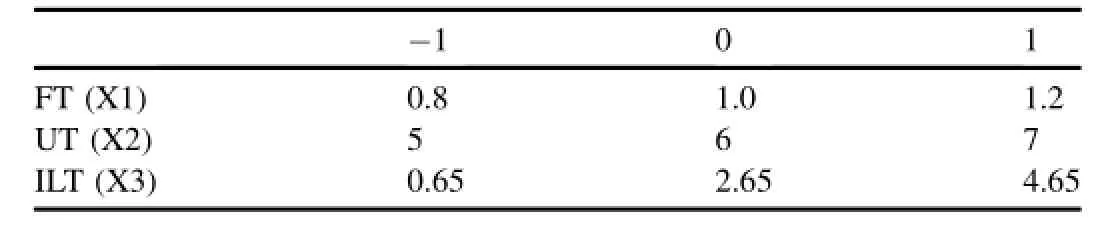
Table 5 Important process parameters.
2.Experim en tal work
2.1.Joint fabrication
The materials used in the experiment are Ti-6Al-4V,SS304L and oxygen free copper(OFC).The rolled round rods w ith100mm in length and 20mm in diameterweremade from Ti-6Al-4V.The chemical compositions and basemetalmechanical properties of the materials at room temperature of 25.4°C were analyzed as per ASME-E-1086-2008 standard and presented in Table 1 and Table 2,respectively.A rotary frictionweldingmachine,asshown in Fig.3,wasused,with a constant speed of 1500 rpm.The standard welding parameters are listed in Table 3 and Table 4.The predeterm ined factors for friction welding were chosen,as given in Table 5.A fter choosing the factors and levels,Box-Behnken design was used to perform the experiments,as listed in Table 6.The Box-Behnken design is an independent quadratic design in that it does not contain an embedded factorial or fractional factorial design.In this design the treatment combinationsare at the m idpoints of edges of the process space and at the center.These designs are rotatable(or near rotatable)and require 3 levels of each factor.Box-Behnken design has the m aximum efficiency for an experiment involving three factors and three levels;further,the number of experiments conducted for this ismuch lesser com pared to a central composite design. Box-Behnken is a second order rotatable design based on 3-level incomplete factorial design.It isa special 3-level design because it does not contain any points at the vertices of the experiment region.This could be advantageous when the points on the corners of the cube represent the level combinations that are prohibitively expensive or impossible to test because of physical process constraints[19-22].
The samples are prepared from the standard 20 mm diameter rod by machining process,and then their edges are polished w ith abrasive cloth of 600-1200 mesh size.This polishing gives low surface roughness value,which isexceedingly important for friction welding of dissim ilarmetal bonding.The prepared materials are fixed in KUKA friction welding machine w ith amaximum pressure of 150 bar.The friction welding facility used is shown in Fig.3.The feed rate of themachinewas set to 0.5mm/sand the experimentswere conducted as per the parameters in Table 4.The process parameters are especially important for heat generation,plastic yielding and other friction related phenomena.The welding was achieved in two phases.
Initially the Joint 1 was prepared w ith stainless steel and copper rod(Fig.4).This jointgivesbetter resultbecause of the purity and softness of copper w ith polished layer.Next,the copper side iscut to 12mm length from joined interface.Then joint 2 was prepared with titanium alloy and copper side of previous joint1,as per previousstepsw ith various parameters. Due to increased upset timemore amounts of copper as flash came out,as shown in Fig.5,which results in different copper thicknessbetween Tialloy and stainless steel.It is considered as interlayer thickness and the outcomes are as shown in Fig.6.The process is repeated for the parameters of the different sam ples in Table 4 and sample tested by drop test. Drop test is performed immediately after the joint is established in order to understand whether bond is intact.The welded sample is dropped from the standard heightof 1m to see whether joint is intact or it gets separated.The sample under study cleared the drop testw ithout being separated due to excellent bonding,which was achieved using the copper interlayer.Thus the specimen is now taken for further investigation.The major constitution was found to be copper by analyzing the flashes in the samp les.This is because of its softness and more heat conducting property.The flashes are removed from the samples by machining.The thicknesses of copper(interlayer)are listed in Table4.Necessary samplesare prepared for further evaluation of mechanical and metallurgical properties.
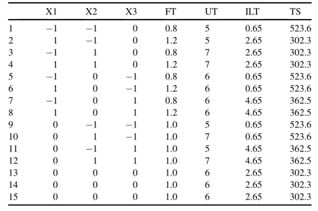
Table 6 Box-Behnken design.

Fig.4.SS304L and copper joint.
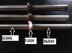
Fig.5.SS304L and Ti-6Al-4V joint.
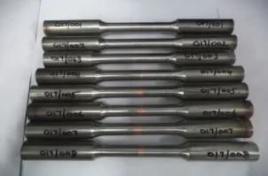
Fig.6.Joints w ith different interlayer thickness.
2.2.Hardness testing
The prepared samples,were subjected to tensile and hardness testing to find out the suitability of service app lication. Initially the specimens were prepared form icro hardness test. M icro hardness testing was done on INNOVATES Vickers hardness testingmachinemodelof 423D w ith 0.01 kgf~2 kgf load.In this test the low load Vickershardness(HV1)method was conducted along the weld centre line at the regular interval of 1 mm apart.The hardness values are presented graphically in Fig.10.Variation in hardness near the centre line is due to HAZ.

Fig.7.M icrostructure of Ti-6AL-4V,interface region and SS 304L.
2.3.Tensile testing
Static tensile testswere performed on the samplesw ith or w ithout stress concentration,which were taken from the welded joints w ith constant speed rotation(1500 rot/min),constantaxial pressure(12 N/mm2)and variable friction time. The prepared specimens are tensile tested as per ASTM standard w ith a gauge length of 50 mm and a diam eter of 12.5 mm(Fig.8).Tensile test was performed at room temperature on the MTSmake UTM having 1000 KN capacity. The test sampleswere loaded on the UTM machine and tested as per the standard.The test values are listed in Table 6.The test shows thatbreaking occurseither in thewelding areaor in the immediate vicinity of the austenitic steel component.
2.4.M icro structure testing
The sam ples for the m icrostructural investigation were prepared by w ire-cut EDM process.The sam ples were polished w ith alumina,magnesia and diamond powders w ithvarious fineness,and then washed and degreased in boiling alcohol and etched w ith reagent for 20 s.Macrostructure and m icrostructure were analyzed by De-W intor trinocular inverted metallurgical m icroscope with magnification of 100× using etching reagent like Kroll's reagent for titanium alloy,pot dichromate for copper and Glyceregia solution for stainless steel.
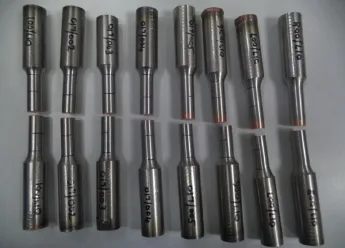
Fig.8.Fractured samples after tensile test.
3.Resu lts
The samples were friction welded.It can be seen from Fig.6 that the heating time,upsettime and interlayer thickness are themajor criteria for joint performance.When the weld interfacesof Sample 13 were analyzed after experimentation,the friction and upset times were 1.2s and 6.5s,respectively. The macro examination of the fractured surface after the tensile test shows the major diffusion of copper on both the sides.For Samp le 15,the heating and upset times were 1.2s and 7s,respectively.In this sample,the interlayer thickness was 0.65 mm,and the fractured surface revealsmore copper diffused on the titanium alloy side and stainless steel side.
M icro-hardness survey was done by Vickers hardnessmachine.The hardness values of the different samples are presented in Fig.10.It isobserved that the hardnessesof stainless steel varied between 271 VHN to 297 VHN which ismore than that of basem etal.The hardnesses of Tialloy and copper vary from 298 VHN to 320 VHN and 77 VHN to 107 VHN,respectively.
The tensile test results of different samples are listed in Table 6.523.6MPa tensile strengthwasobtained for0.65mm thick interlayer.The tensile strength reduces gradually as the interlayer thickness increases.The values of tensile strength rangesbetween 302.3 and 523.6MPa.The diffusion of copper on both thesidesof the joint isgood and the tensilestrength is remarkable w ith interlayer thickness between 0.65 and 0.85 mm.

Fig.9.Fractured face of failure samp le 1 after tensile test.
4.Discussion
4.1.Hardness study
From the observed value it's found out the hardness of stainless steel is increased by 15%-20%,the hardness of copper is increased by 23%,and the hardnessof Tialloy side is the lowest.It isobserved that the increase in the hardnesses of stainless steel and copper side is due to high temperature rise and upset pressure in theweld zone.The parentmetal of stainless steel w ith austenitic structure was changed to martensite in copper side due to high upset pressure and rapid atmospheric cooling;the metal characters were completely changed w ith high hardness.Because of a higher regional velocity at the peripheral region,the temperature at the peripheral region was higher than that of the central region.It accelerated the inter diffusion of Ti,Aland Cu at the interface. The formation of intermetallic compound at peripheral region could be explained by a higher temperature.The phase transformed region observed at the SS 304L side remarkably decreased and was lim ited to less than 0.5 mm from theweld interface.Fig.10 shows the hardness distribution near the interface using insert layer.AtSSside,a remarkable hardened region due to the martensite structure was formed w ithin 0.3 mm from the SS/copper interface.In the copper region,slight softening occurred due to recrystallization and annealing effect caused by welding heat.
4.2.Tensile test properties
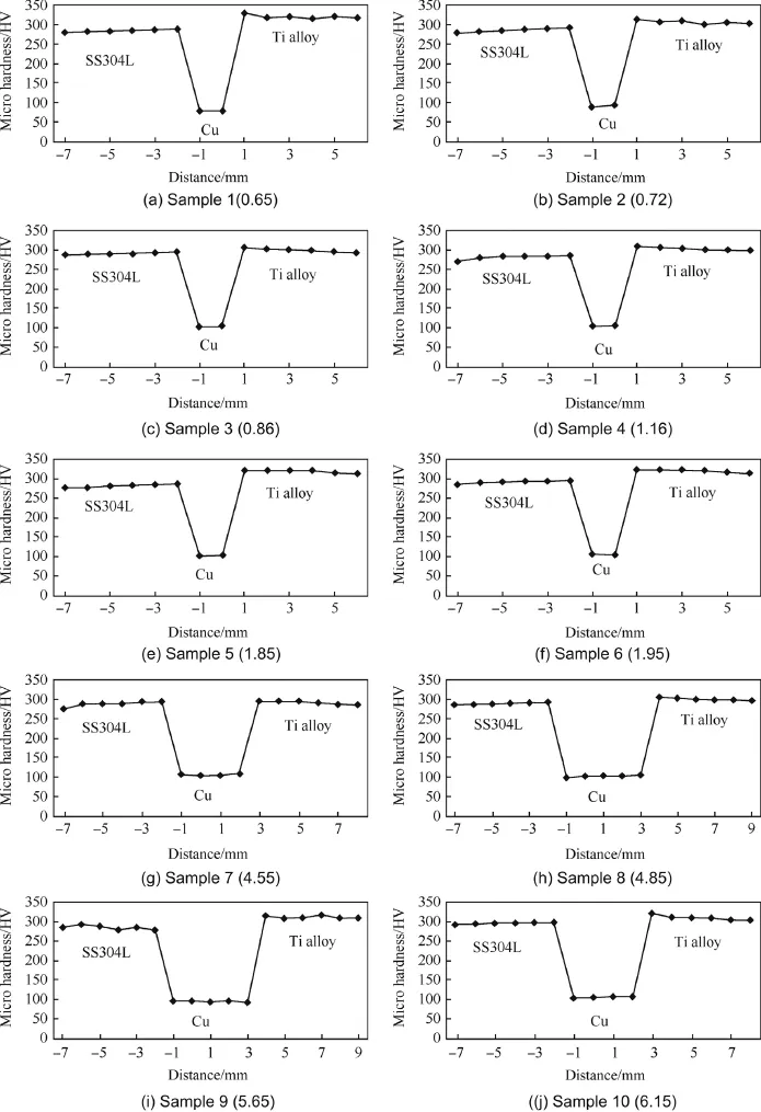
Fig.10.Hardnesses of samples of ILT from 0.65 to 6.15 mm.
Ti-6A l-4V and X 5CrNi18-10 dissim ilar FW joints w ithout interlayers have tensile strength between 340M pa and 380 M pa[8],Pure titanium and SS304L w ith different interlayer revealed that the tensile strengths of Ti/Ni/SS304L,Ti/ Ta/SS304L,Ti/V/SS304L and Ti/Ta/Ni/SS304L were 410Mpa,394Mpa,388Mpa and 388M pa,respectively[11]. Previous work done w ithout interlayer as in the case of Ti alloy and stainlesssteelalso produced lower tensilestrength of 340Mpa[8].It isalso evident from the previous literature that the copper has notbeen used as interlayerw ith titanium alloy and SS304L.The present study of copper interlayer proved that higher tensile strength is possible.From the experimentation it is observed that the maxim um tensile strength of 523.6 MPa was achieved,which is closer to the strength of SS304L basemetal.From the findings the strength graduallyreduces if the copper interlayer thickness increases.Another significant observation is that the bonding of copper between Ti alloy and stainless steel is equally well because of high friction time of 1.2 s and upset time of 7 s(Fig.9).When friction time and upsetting time are short,the copper debonding takes places at Ti alloy side during tensile testing,so it needsmore upset time for superior bonding.TiAl(Titanium aluminide)and AISI4140 steelw ith copper insert layer[18]revealed that the tensile strength increased w ith decrease in layer thickness,and for an interlayer thickness of 0.6 mm,the tensile strength was about 250 MPa.W hen the interlayer thickness was reduced to 0.3 mm and 0.2 mm,the average tensile strength was about 345 MPa or 375 MPa.The present investigation of SS 304L and Tialloy w ith copper as interlayer has proven to have the highest tensile strength of 523.6 MPa w ith an interlayer thicknessof 0.65mm.When the Tialloy is combined with stainless steel,a pronounced deformation is noticed because of frictional heating,and the transformation from Ti alpha to Ti Beta takes place accompanied by the decrease ofmechanical resistance.By increasing the friction time and maintaining the constant rotational speed and axial pressure,a quality welded jointw ithout defects is achieved.

Fig.11.SEM and EDX results of stainless steel and copper interface.

Table 7 Elements comparison of basemetal and SS-copper location.
4.3.M icrostructural investigations
The prepared specimen for m icrostructural investigation was observed through opticalmicroscope.The stainless steel matrix far away from the center shows the parent metal microstructurewith Equi-axed grainsof austenite.Some strain band is due to the hot extrusion of the stainless steel(Fig.7(a)).The interface zone is not in a straight line and varies according to the upset pressure and also shows the plastic deformation of both themetals(Fig.7(b)).The Tialloy microstructure shows the presence of acicular alpha phase Transformed into beta phase(Fig.7(c)).Them icrostructure of Ti alloy at the center show s some formation of alpha prim e phase due to heating and cooling(Fig.7(d)).Themicrostructure of the copper shows the presence of alpha phase in transformed betamatrix as seen in Fig.7(e),and the interface zone of the copper and stainless steel isvisualized as the dark diffusion zone(Fig.7(f)).The interface zone of the Ti alloy w ith copper showsalpha prime structure(Fig.7(g)and interfacezone of SS304Lw ith copper isasshown in Fig.7(h).
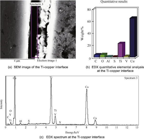
Fig.12.SEM and EDX results of Tialloy and copper interface.
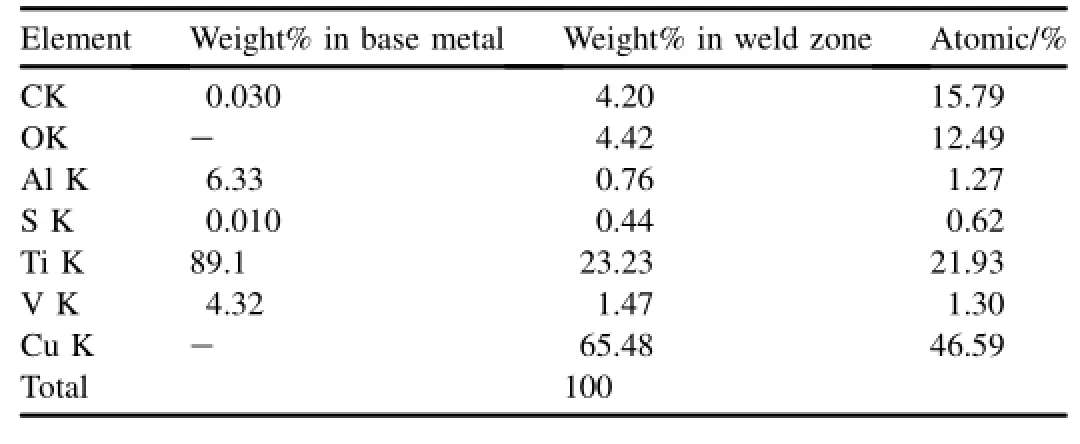
Table 8 Elements comparison of basemetal and Tialloy-copper location.
4.4.SEM-EDS analysis
Scanning electron m icroscopy(SEM)and energy dispersive X-ray(EDS)analysis were performed to find out the elemental distribution at the interface region.The observed results were analyzed under 20.00 kV field effect scanning electron microscope through energy dispersive x-rays(EDS)analysis.SEM microstructure of the stainless steel and copper interface region(Sample 2)reveals some intermetallic compoundsasseen in Fig.11(a)-(c),and EDSanalysis resultsare shown in Table 7.It is evident that the solubility of copper(14.52%by weight)is seen in the stainless steel region.SEM and EDX results of Ti alloy and copper side(Sample 3)are shown in Fig.12 and tabulated in Table 8.Here also it is evident that thesolubility of copper in the Tialloy side ismore than those of any otherelements,and the solubilitiesof Tiand other elements like vanadium are reduced.
From EDS result it is confirmed that more elements of copper diffused on both sides of base metal as intermetallic compounds and there is no direct contact between the both parent metals.Such intermetallic region has improved the bonding strength and high tensile strength compared to direct bonding.Though the binary phase diagram of Cu-Ti indicatesthe occurrence of various Cu-Ti intermetallic phases with increase in Cu content,the low melting point of copper encourages an improved contactarea in themating surfaces.The welds of titanium alloysw ith steels suffer from the brittleness of resulting intermetallic compounds like Ti-Fe and Ti-Cr. Thenature and the localization of intermetallic phases in these weldswere studied by SEM,EDS,XRD and micro hardness measurements.The localaccumulation of Cu3-Tibased phase is less detrimental to the strength of thewelds,which makes joining possible(Fig.13).
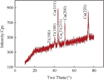
Fig.13.Diffraction patterns of Ti and SS w ith copper interface.
5.Conclusions
A comparative study was performed to understand the friction welding characteristics of Ti-6A l-4V and SS304L w ith copper as interlayer and w ithout interlayer.Based on the investigations performed,we conclude the follow ing.
1)From the literature and ourexperimental results,theparent metalsw ithout interlayerwaswelded,but the joint failed in the drop test.Thiswas due to the crack formation,and the brittle intermetallic compound w ith martensite phase resulted in a lower strength.
2)For dissim ilarmaterials like dual phasematerials,a poor jointwas observed when itwas attempted to join directly. The presence of copper interlayer in this jointhas p layed a significant role in obtaining excellentbonding between Ti alloy and stainless steel w ithout crack and preventing major martensitic changes.Moreover the addition of copper as interlayer has produced high tensile strength in the order of 523.6 MPa as compared to the joints established w ithout interlayer.
3)In mechanical and metallurgical characterization of the welded samples,it is observed that the samples with m inimum interlayer thickness have produced better results.
4)Hardness at the interface was increased by 23% compared to OFC copper.Hardness in the SS 304L region was also increased by 15-20%com pared w ith the SS parentm aterial.The parentmetal of stainless steel w ith austenitic structurewas changed tomartensite in copper side due to high upset pressure and rapid atmospheric cooling;the metal characters are completely changed w ith high hardness.
5)From EDS result it is confirmed thatmore elements of copper diffused on both sides of base metal as intermetallic compounds and there is no direct contact between both the parent metals.It can be concluded that the insertion of pure copper interlayer allow s reducing the formation of brittle Ti-Fe and Ti-Cr-based phases.The local accum ulation of Cu3-Ti based phase is less detrimental to the strength of thewelds,whichmakes joining possible.Such intermetallic region has improved bonding strength and high tensile strength compared to direct bonding of the twometals.
Acknow ledgm ent
The author isgrateful to Welding Research Institute(WRI),Trichy,for extending their facility for fabricating the samp les for the above research work.The authors also w ish to express their sincere thanks to allstaff of the consulting departmentof WRI for their cooperation in the preparation of the samples.
[1]Ambroziak A,Korzeniow skiM,Kustro'n P.Frictionwelding of dissim ilar metal joints w ith intermediate layers.J Achiev Mater Manuf Eng 2007;21(2):37-40.
[2]Montgomery Jonathan S,Wells M artin GH,Roopchand Brij,Ogilvy James W.Low-cost titanium armors for combat vehicles.M inerals MetalsMater Soc 1997;49(5):45-7.
[3]ColaMJ,Dickerson RM,Gentzlinger RC,Teter DF.Dissimilarwelds for the apt superconducting cavity's cryogenic plumbing system.In:Proceedingsof the 1999Workshop on RF Superconductivity,Santa Fe,New Mexico,USA;1999.
[4]LeeWon-Bae,Jung Seung-Boo.Effectofmicrostructure onmechanical properties of friction-welded joints between Ti and AISI 321 stainless steel.Jpn Inst M etalsM ater Trans 2004;45(9):2805-11.
[5]Astarita,Curioni M,Squillace A,Zhou X,Bellucci F,Thompson GE,etal.Corrosion behavior of stainless steel-titanium alloy linear friction welded joints:galvanic coupling.Mater Corros 2014.http://dx.doi.org/ 10.1002/maco.201307476.
[6]Madhusudhan Reddy G,Mohandas T,Sambasivarao A,Satyanarayana VV.Influenceofwelding processesonmicrostructure and mechanical properties of dissimilar austenitic-ferrite stainless steel welds.M ater M anuf Process 2005;20(2):147-73.
[7]Balasubramanian M,Jayabalan V,Balasubramanian V.Optimizing the pulsed currentGTAW parameters to attainmaximum impact toughness. Mater Manuf Process 2008;23:69-73.
[8]Cosm in Groza A,Ion M ite lea A,Dim ian M arcela Elena.M echanical and structural characteristics of friction welded TI-6AL-4V+X5CRNI18-10 dissimilar joints.Metal 2011;5:18-20. Brno,Czech Republic,EU.
[9]Shamanian M,SalehiM,SaatchiA,North TH.Influence of Ni interlayer on themechanicalpropertiesof Ti6Al4V/(WC-Co)friction weld.Mater Manuf Process 2003;18(4):581-98.
[10]Davari H,Parsa MH,Hadian AM,Nili Ahmadabadi M.Experimental and numerical thermomechanical analysis of hybrid friction welding ofcommercially pure copper bar.Mater Manuf Process 2011;26(5):694-702.
[11]Ashfaq M,Prasad Rao K,Khalid Rafi H,Murty BS,Dey HC,Bhaduri AK.Friction welding of titanium to 304L stainless steel using interlayer©Carl HanserVerlag.Mu¨nchen Prakt Metallogr 2011;48(4):188-207.
[12]Madhusudhan Reddy G,VenkataRamana P.Role of nickel as an interlayer in dissimilarmetal frictionwelding ofmaraging steel to low alloy steel.JMater Process Technol 2012;212(1):66-77.
[13]Sassani F,Neelam JR.Friction welding of incompatiblematerials.Weld Res Suppl November 1988;11:264s-70s.
[14]Rajesh Jesudoss Hynes N,Nagaraj P,Angela Jennifa Sujana J.Investigation on joining of aluminum and mild steel by friction stud welding. M ater M anuf Process 2012;27(12):1409-13.
[15]Lukin VI,Koval'chuk VG,Samorukov Yu ML,Gridnev M,Zhegina IP,Kotel'nikova LV.Effectof frictionwelding parametersand heat treatment on the quality of welded joints in creep-resisting deformable nickel alloys.Weld Int 2012;26(9):728-31.
[16]Shanjeevi C,SatishKumar S,Sathiya P.Evaluation ofmechanical and metallurgical properties of dissim ilar materials by friction welding. Procedia Eng 2013;64:1514-23.
[17]Kimura Masaaki,Saitoh Yoshitaka,Kusaka Masahiro,Kaizu Koichi,Fuji Akiyoshi.Effect of friction welding condition and weld faying surface properties on tensile strength of friction welded joint between pure titanium and pure copper.J Solid Mech Mater Eng 2011;5(12):849-65.
[18]LeeWon-Bae,Kim Young-Jig,Jung Seung-Boo.Effectsof copper insert layer on the properties of friction welded joints between TiA l and AISI 4140 structural steel.Intermetallic 2004;12:671-8.
[19]Box GEP,Hunter WG,Hunter JS.Statistics for experimenters.New York:Wiley;1978.
[20]Box GEP,W ilson KB.JR Stat Soc B 1951;13:1-45.
[21]Box GEP,Benhken DW.Technometrics 1960;2:195-219.
[22]Montgomery CD.Design and analysis of experiments.Singapore:John Wiley and Sons,Pte.Ltd;2001.
.
E-mail addresses:kumarramalingam62@gmail.com(R.KUMAR),manianmb@gmail.com(M.BALASUBRAMANIAN).
Peer review under responsibility of China Ordnance Society.
http://dx.doi.org/10.1016/j.dt.2014.10.001
2214-9147/Copyright©2015,China Ordnance Society.Production and hosting by Elsevier B.V.All rights reserved.
Copyright©2015,China Ordnance Society.Production and hosting by Elsevier B.V.All rights reserved.
- Defence Technology的其它文章
- Prediction of flow stress of 7017 alum inium alloy under high strain rate compression at elevated temperatures
- Semi-analyticalmethod for calculating aeroelastic effect of profiled rod flying at high velocity
- Feasibility analysis ofWDM links for radar applications
- Study of high-speed interaction processesbetween fluoropolymerprojectiles and alum inum-based targets
- M icrostructure and corrosion behaviour of gas tungsten arc welds of maraging steel
- Performance characterization of Ni60-WC coating on steel processed w ith supersonic laser deposition