Influence of machining parameters on groove surface morphology of condenser for heat column
Su-lian TAO, Qin-he ZHOU, Shi-dan WEI
(Department of Mechanical Engineering, Guangdong Technical College of Water Resources and Electric Engineering, Guangzhou 510925,China)
Influence of machining parameters on groove surface morphology of condenser for heat column
Su-lian TAO*, Qin-he ZHOU, Shi-dan WEI
(Department of Mechanical Engineering, Guangdong Technical College of Water Resources and Electric Engineering, Guangzhou 510925,China)
Surface structure of condenser for heat column plays a vital role on its heat transfer performance; micro groove surface roughness is beneficial to the enhancement of condensation and heat transfer performance. The experiment machining method of manufacturing micro grooves on condenser surface for heat column is introduced in this paper; a finite element model machining the condenser for heat column by plough- extrusion (P-E) tool is established,P-E process is simulated using the Deform software; forming process and manufacturing mechanism of micro grooves are analyzed. Experimental results show that feed and P-E depth play important role on surface morphology of micro grooves on condenser, V-shaped grooves are formed when machining ringed grooves on the surface of condenser, U- shaped grooves are formed between two adjacent V- shaped grooves, there are bumps at two end of V- shaped groove,which form fins. Orthogonal micro grooves are formed on the surface of condenser when axial grooves are processed, which present many U- shaped micro grooves. Feed and P-E depth play important role on micro groove surface morphology: the larger the P-E depth, the coarser micro groove surface morphology.but the P-E depth can’t be too large because the tool intensity and stiffness are limited. It is disadvantage for the forming of micro groove surface morphology when the feed is too large or too little. Only when the feed is right, can be formed excellent micro groove surface morphology
Heat column, Groove morphology, Plough-extrusion, Finite element simulation
1 Introduction
The main function of condenser for heat column is to ensure the vapor condensate and condensation liquid return from condenser to evaporator. The wick structure of condenser plays a crucial role on its heat transfer performance [1-2]. Rough surface morphology can improve condensing performance [3]. Micro grooves with rough surface morphology were manufactured on inner wall of small copper tube by P-E, which were used in micro groove heat pipe; it can enhance capillary function [4-6]. Nowadays the wick on inner wall of heat pipe is manufactured mainly by mechanical processing [7-8], laser processing [9], sandblasting, flame spray [10], pyrogenation galvanization [11], sintering [12-14] and so on. Mechanical manufacturing micro groove fin is applied widely because of its canonical, simple molding techniques and mass production. Micro groove fins forming methods such as micro etching, micromachining and precision milling belong to mechanical processing, but all the methods are either costly or complex. Compared to mechanical processing method, P-E belongs to chip less machining, micro groove surface morphology manufactured by P-E is rougher than that manufactured using ordinary mechanical processing method and which can form complex surface structure composed of micro structure and sub-structure. It leads to heavy workload and high cost relying solely on experimental optimization of machining parameters, this paper presents an application of finite element simulation in experiment, it is simulated using Deform software by which micro grooves on condenser of heat column are manufactured with P-E tool on lathe, different processing parameters affect micro groove surface morphology of condenser are studied, proper processing parameters are gotten, the parameters are used in practical machining and provides theory for guidance actual processing.
2 Experimental process and finite element modeling
2.1 Experimental procedure and tool design
P-E process is carried out on lathe C6132A1. The material of condenser is red copper tube with a diameter of 32 mm and a thickness of 1 mm, and the tool is made of high-speed steel(W18Cr4V). The wick structure of condenser is formed twice; a mould is fixed outside of copper tube in order to reduce the deformation of copper tube. The copper tube is fixed in the lathe chuck, the main spindle rotates to drive copper tube to rotate, the P-E tool is fixed on a home made knife nest which is fixed on tool slide, the tool feeds axially at the same time, then a series of ringed micro-grooves are formed on the inner wall of copper tube. The processing diagram is shown in Fig. 1. The copper tube is fixed during the second forming, the P-E tool moves axially, thus an axial groove perpendicular to the ringed grooves is formed. Then, the lathe chuck rotates a certain angel, the second groove is formed, and so on, a series of axial grooves are formed, thus multi-scale fin structure is formed.
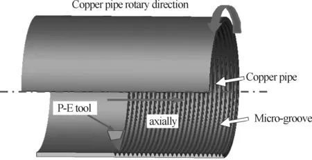
Fig.1 Processing schematic diagram of condenser diagram
The schematic diagram of the forming tool is shown in Fig.2. It consists of a plough edge, a primary extruding faceAγ, a minor extruding faceAγ′, a primary forming faceAβand a minor forming faceAβ′. TheP0-P0cross-section of the tool is wedge structure whose front end is the plough wedge. The tool is designed to be thin in shape to make force acting on tool small enough to prevent the tool from collapsing during P-E process. The relationship between the primary extruding angles and minor extruding angles should satisfy the following condition [15]:
(1)
Whereγ0is the primary extruding angle,γ0′ is the minor extruding angle,βis the primary forming angle, andβ′ is the minor forming angle,Eαis flank of tool,Kγandαare rake and clearance angle of tool, respectively
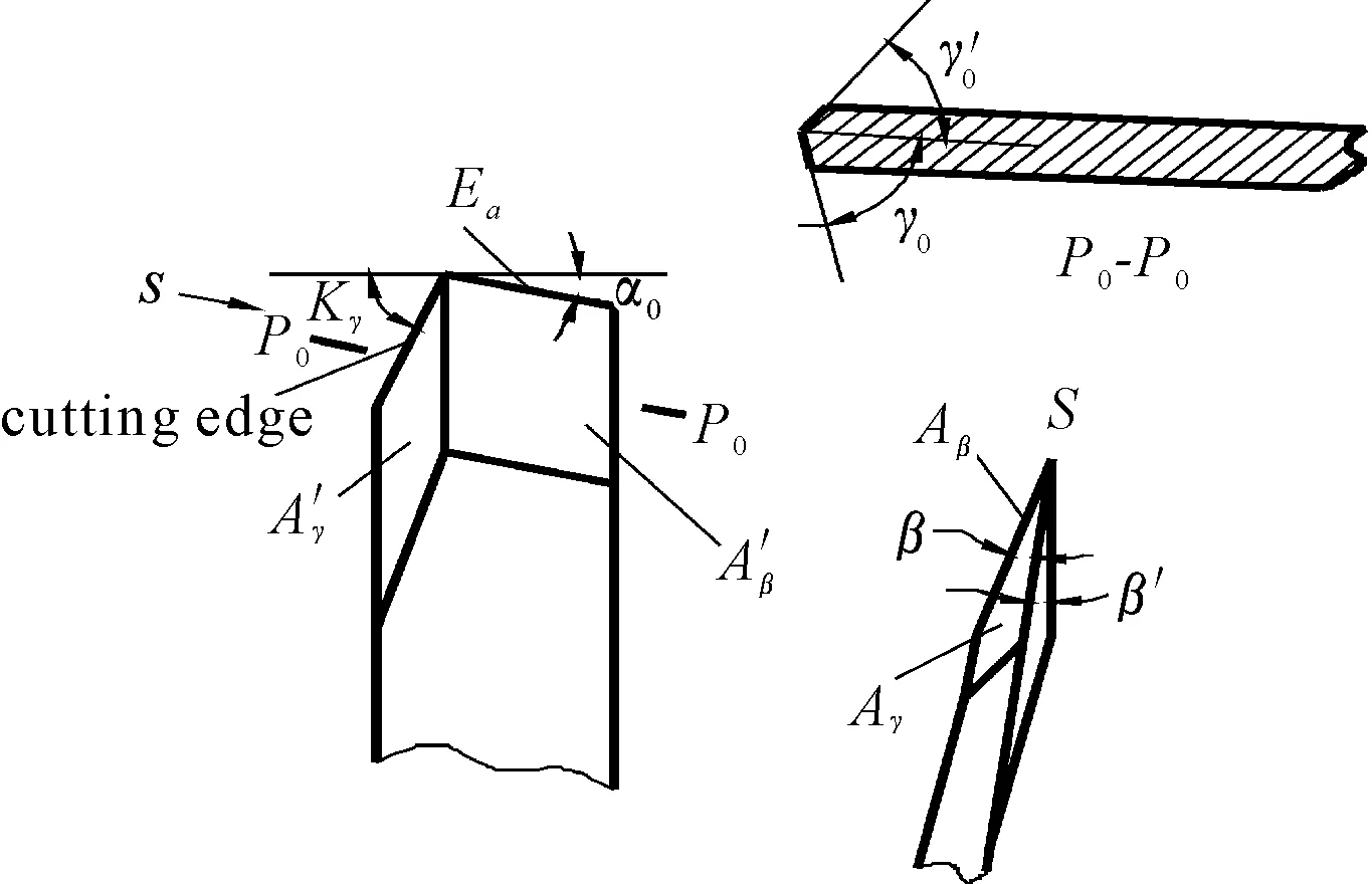
Fig.2 Plough-extrusion tool schematic
2.2 Geometry model and gridding model
The work piece rotates with lathe chuck; the tool feeds axially when the condenser of heat column is machined. The work piece is fixed and the tool rotates along axis of heat column when simulation is running. A small part of heat column is used considering that the tube (plastic body) is axisymmetric and the simulation requires stabilization and simplification. The tube rotates in 1 rad/s around central axis, while the tool feeds in a range of 0.2-0.6 mm axially; the feed depth in a range of 0.1-0.3 mm during ploughing. P-E simulation model is shown in Fig. 3.
Tool model and work piece model are established and exported to Deform 6.0, rotary speed is set and then the mesh of work piece is divided into 80000 elements. Besides two subdivision mesh windows named Window 1 and Window 2 are set up. Window 1 is a cirque columniation fixed window which includes the path of P-E tool and fins forming area after P-E tool ploughs and extrudes. Window 2 is a cuboid window which covers formed area of work piece around tool point. It moves together with tool point. The scale factor between the grid of finer mesh windows and exterior mesh is 0.01, as shown in Fig.4. Plane ABEF、plane CDGH and plane ADGF are set as boundary conditions; the speed of work piece on these three surface planes is zero.

Fig.3 Finite model of condenser for heat column

Fig.4 Reseau division of simuation model
3 Results and discussion
3.1 Ringed groove
3.1.1 Influence of P-E depth on micro groove morphology
The formed groove morphology of work piece is similar at different P-E depth, as shown in Fig.5.when the P-E depth is 0.1, 0.2 and 0.3 mm separately, the grooves of work piece are V-shaped all, when P-E depth is larger, the groove is deeper and wider, then more metal piles up both side of grooves, the higher fins, moreover the bigger and thicker drum bound around fins.

Fig.5 Groove topography of different P-E depth
3.1.2 The influence of feed on micro-groove
Two ringed grooves are simulated for saving time. The influence of feed on formed groove morphology is shown in Fig.6. When feed is 0.2 mm, the second ringed groove is wider than natural initial groove; moreover the deformation of metal between two grooves is acute, which is inclined to the initial groove. When the feed is 0.4 mm, the metal between two grooves occurs large deformation, and it is U-shaped. When the feed is 0.6 mm, the area between two grooves presents U- shaped, andtit is wider than that formed at 0.2 mm and 0.4 mm. The larger feed, the less impact of the first ringed groove on the second; the less feed, the more impact of the first groove on the second, it leads lager plastic deformation occurred the metal between two adjacent grooves. When the feed is too little, the surface morphology between two grooves is not ideal.

Fig.6 Effect of feed on groove topography
3.2 Simulation of axial groove
3.2.1 Geometry model and gridding dividing
The axial groove of condenser is manufactured after the ringed groove is manufactured. The simulation of axial groove for condenser is accomplished at the base of the simulation of ringed groove for condenser. The simulated ringed grooves model is imputed Deform software, then P-E tool is imported to required position, as shown in Fig.7 (a). Fig.7 (b) is the processing sketch map of axial groove for condenser.
After fixing the work piece, P-E tool moves along rotary axis of work piece linearly at the moment of simulation. The specific processing parameter follows: the linear velocity of P-E tool along rotary axis is 10 mm/s; the P-E depth is 0.3 mm. Three feeds including 1/360 rad, 1/180 rad and 1/90 rad are selected for experimental verification. Then the mesh of work piece is divided into 120 000 elements. Two subdivision mesh windows named Window 1 and Window 2 are set up. Window 1 is a cuboid fixed window which includes fins being formed area after P-E tool plough and extrude; Window 2 is a cuboid window which covers formed area of work piece around tool point. It moves together with tool point. The scale is 0.01 that the grid of finer mesh window1 relative to exterior mesh, as shown in Fig.8. Plane ABDC, plane EFGH and plane ACFG are set as boundary conditions; the speed of work piece on these three planes is zero. The rest planes are not restricted in order to the forming of chips and micro-grooves, the gridding model is shown in Fig.8.
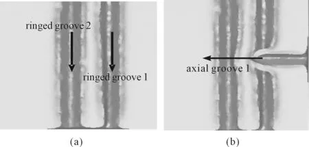
Fig.7 Axial groove simulation model of condenser
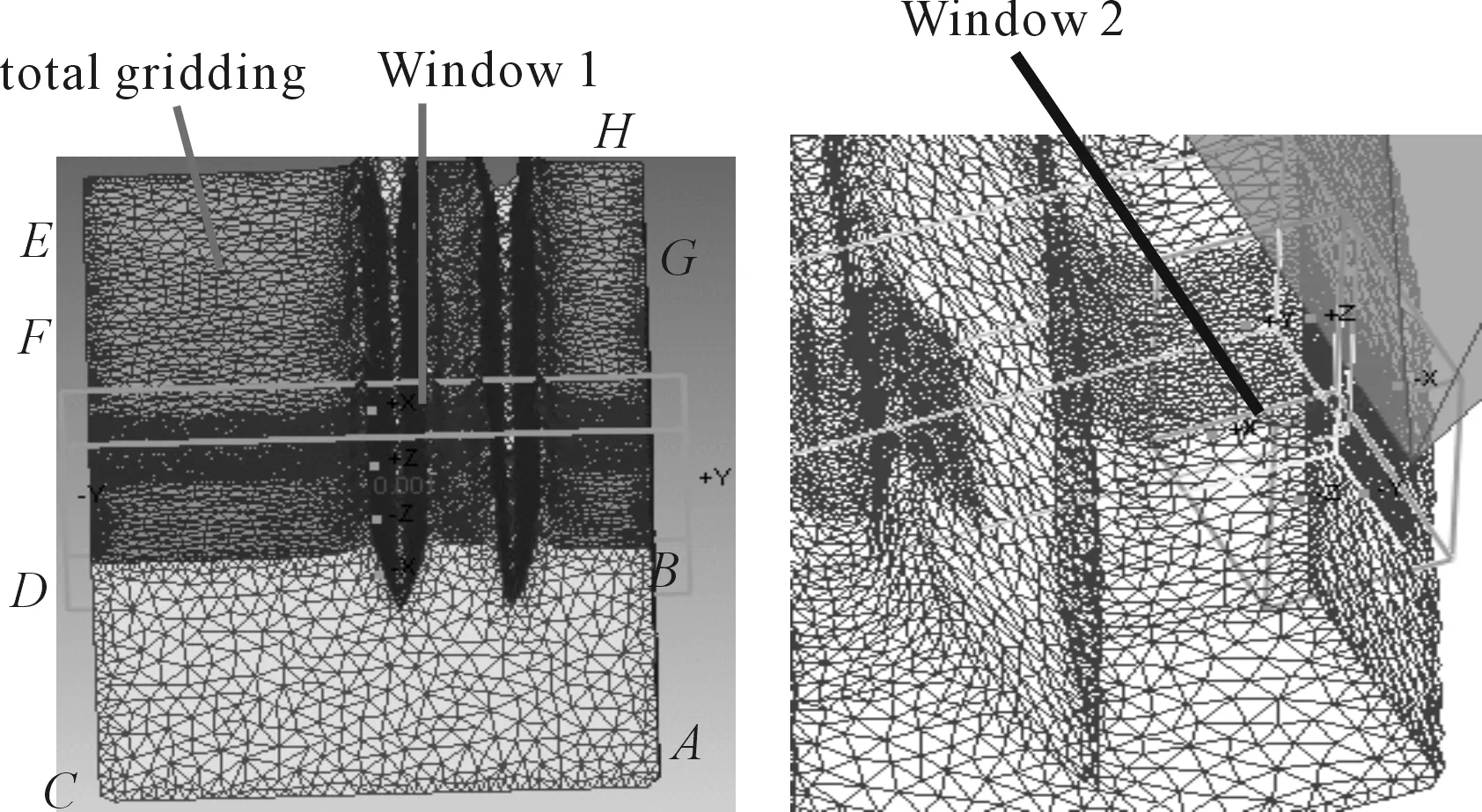
Fig.8 Roseau dividing model of workpiece
3.2.2The forming analysis of orthogonal micro-
grooves
The forming of axial grooves has a certain influence on the forming of annular grooves. Many mutual orthogonal micro-grooves are formed at condenser, and it presents many U-shaped grooves, the forming process is shown in Fig.9. Fig.9(a) shows cut-in phase; Fig.9(b) shows orthogonal phase; Fig. 9(c) shows cut-out phase; Fig.9(d) shows a cut-in phase of the second axial grooves in the process of orthogonal grooves forming. Fig.9(e) shows the orthogonal process of the second axial grooves in the process of orthogonal grooves forming. Fig.9(f) shows cut-out phase of the second axial grooves in the process of orthogonal grooves forming. The forming of axial grooves bases on the forming of two ringed grooves. When the first axial groove is processed, the tool begins cutting metal; a part of cutting metal is split and extruded to two sides of axial groove and form fins. Another part of metal attached to tool front face moves along tool. When tool moves to the first ringed groove, the metal moved with tool deforming sharply due to no metal at the first ringed groove. When the tool keeps on moving to go over the first ringed groove, the formed axial groove cut off the first ringed groove, and then the tool keeps on moving. When tool moves to the metal between two ringed grooves, P-E force increases suddenly. The P-E force falls when the tool falls across the second ringed groove with the continuous movement of tool. The P-E force begins to increase again when P-E tool cuts out the second ringed groove, goes round and round until the P-E end. The forming mechanism of ploughing and extruding the second axial groove is similar as that of the first axial groove. When the second axial groove is processed, the first formed axial groove has effect on it. We can be seen from the figure 9 where exist many orthogonal grooves and it comes into being many U-typed holes on the surface of condenser when the process parameters of ringed grooves and axial grooves are right.

Fig.9 Forming process of intersecting grooves of condenser
3.2.3 Infulence of feed on groove morphology
Fig.10 shows the surface morphology formed when the ringed groove space between is 0.4 mm, the axial grooves space between is 1/360 rad,1/180 rad,1/90 rad respectively, the depth of ringed groove and axial groove are both 0.3 mm. We can see from the figure that when axial groove feed is too little, as Fig.10(a), the second groove has an acute impact on initial groove, which makes metal between two grooves pack up, so it can’t form good condensation structure; when axial feed is too large, the forming of the second groove has little impact on the initial groove and the fins formed between the ringed grooves. The ringed groove keeps the former groove feature, the fin is not high, the groove morphology is not ideal. Only when the axial groove space between is in a certain range, the impact of two adjacent axial groove is right, and the impact of axial groove on ringed groove is right, and then the micro groove morphology shows U-typed hole, raised fins is around holes, it is a perfect intensified condensation structure.
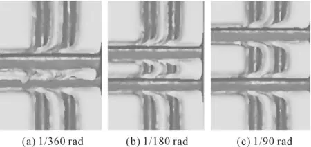
Fig.10 Effect of feed rate on intersecting grooves
4 Conclusion
The feed and depth of plough and extrusion have large impact on microgroove surface morphology. The larger P-E depth, the deeper and wider the micro-groove, the bigger and thicker micro-groove fin, the better the surface morphology, the P-E depth can’t be too large because of the limit of tool strength and system stiffness.The bigger the feed, the less impact between micro-groove; contrarily, the more impact. Only mezzo feed can make surface morphology formed on the condenser of heat column better. What we can get from FEM: when P-E depth is 0.3 mm, ringed feed is 0.4 mm and axial feed is 1/90 radian, there formed better surface morphology on condenser.
Acknowledgement
This work is financially supported by Natural Science Foundation of Guangdong Province, China (No.S2013040013066) and the 2014 annual university outstanding young teachers training plan of Guangdong Province.
[1]Tao sulian,Tang yong, Pan Minqiang. Forming Technics and Optimizing Study of Composite Wick Structure for Heat Column [J]. Journal of south china university of technology:natural science edition, 2011, 39(6): 29-35.
[2]TAO Su-lian, TANG Yong, PAN Min-qiang, et al.Forming method of wick structure for heat column [J]. Trans.Nonferrous Met.Soc.China, 2011(21):1587-1594.
[3]Kang S W, Huang D. Fabrication of star grooves and rhombus grooves micro heat pipe [J].Journal of Micromechanics and Microengineering, 2002, 12: 525-531.
[4]Liu X Q, Tang Y, Pan M Q, et al. Manufacturing heat pipe by combined ploughing-extrusion process [C]// Proceedings of the International Conference on Integration and Commercialization of Micro and Nanosystems, 2007: 1417-1422.
[5]Chen P, Tang Y, Liu X K, et al. Formation of integral fins function-surface by extrusion-ploughing process [J]. Transaction of Nonferrous Metals Society of China, 2006, 16 (10): 1029-1034.
[6]Tang Yong, Chen Ping, Wang Xiaowu. Experimental investigation into the performance of heat pipe with microgrooves fabricated by Extrusion-ploughing process. Energy Conversion and Management, 2010 (51): 1849-1854.
[7]Thome R, John H. Reboliers with Enhanced Boiling Tubes[J]. Heat TransferEngineering, 1988, 9(4): 45-61.
[8]Marto D J, Epere V J L. Pool Boiling Heat Transfer From Enhanced Surfaces to Dielectric Fluids[J]. Advances in Enhanced Heat Transfer, ASME HTD, 1981, 18:93-102.
[9]Tan huayu, Gao chunyang, Liu lixin. Manufacturing Methods of Porous Surface and Comparison of Enhanced Boiling Heat Transfer Effect [J]. Fluid Machinery, 2006, 34(1): 80-85.
[10]Michael M D, Lester D E. Liquid heat exchanger interface and method[P]. UnitedStates Patent 3990862, Nov. 9, 1976.
[11]Clarence E A. Boiling heat transfer surface and method [P]. United States Patent 4018264, Apr. 19, 1977.
[12]Scott G L, Massoud K. Pool-boiling CHF enhancement by modulated porous-layer coating: theory and experiment [J]. International Journal of Heat and Mass Transfer, 2001, 44(22): 4287-4311.
[13]Weibel J A, Garimella S V. Visualization of vapor formation regimes during capillary-fed boiling in sintered-powder heat pipe wicks[J]. International Journal of Heat and Mass Transfer, 2012 (55) : 3498-3510.
[14]Leong K C, Liu C Y. Characterization of sintered copper wicks used in heat pipes [J]. Journal of Porous Matericals, 1997, 37(4): 303-308.
[15]Chi Yong, Tang Yong, Chen Jin-chang, et al. Forming process of cross-connected finned micro-grooves in copper strips [J].Transactions of Nonferrous Metals Society of China, 2007, 17(2): 267-272.
加工参数对热柱冷凝端微沟槽形貌的影响
陶素连*, 周钦河, 韦世丹
广东水利电力职业技术学院, 广州510925
热柱冷凝端的表面结构对其传热性能的影响起着至关重要的作用,粗糙的微沟槽表面形貌有利于强化冷凝。提出了热柱冷凝端表面加工微沟槽的实验加工方法,建立了犁切挤压刀具加工热柱冷凝端的有限元模型。利用deform软件模拟犁切挤压刀具加工热柱冷凝端微沟槽,分析了微沟槽的成形过程及机理。有限元模拟结果表明:在加工环状沟槽时冷凝端表面形成了V形沟槽,两V形沟槽之间形成U形沟槽,V形沟槽两端有鼓包,形成沟槽翅。在轴向沟槽加工时,表面形成了相互正交的微沟槽,呈现许多U形微沟槽。进给量和犁切挤压深度对热柱冷凝端微沟槽形貌起着重要作用,犁切挤压深度越大,微沟槽表面形貌越粗糙,但是受刀具强度和刚度的影响,犁切挤压深度不能过大。进给量过大和过小,都不利于微沟槽表面形貌,只有当进给量恰当,才能形成最优的微沟槽表面形貌。
热柱;沟槽形貌;犁切挤压;有限元模拟
15 November 2014; revised 19 January 2015;
Su-lian TAO, Associate professor,
Ph.D., graduated from South China University of Technology. E-mail: taosl@gdsdxy.cn
10.3969/j.issn.1001-3881.2015.18.021 Document code: A
TN305.94;TG506
accepted 2 March 2015
Hydromechatronics Engineering
http://jdy.qks.cqut.edu.cn
E-mail: jdygcyw@126.com
- 机床与液压的其它文章
- Manufacturing of self-lubricating diamond tools with Ni-Cr alloy adding with Ni/C
- Vibration response analysis of a lathe spindle by using the ANSYS finite element method
- Car following model with consideration of the vehicle’s mechanical inertia effect and its stability analysis
- Software design for spur gear tooth thickness based on MATLAB/GUI
- Dynamic study on ultrasonic horn
- Analysis and research of OPC technology in coal mine monitoring data transmission system

