Reliable Remote Relay Protection in Smart Grid
Jiapeng Zhang and Yingfei Dong
(Department of Electrical Engineering University of Hawaii,Honolulu,HI 96822,USA)
Reliable Remote Relay Protection in Smart Grid
Jiapeng Zhang and Yingfei Dong
(Department of Electrical Engineering University of Hawaii,Honolulu,HI 96822,USA)
As the false trips of remote protection relays are among the main reasons behind cascading blackouts,it is critical to design reliable relay protection.Even though common protection schemes on traditional power systems have been investigated for a few decades,cascading failures in recent years indicate more research needed in this area.Consequently,researchers have proposed agent-based methods on the Smart Grid(SG)to address this issue.However,these existing agent-based methods simply use TCP protocol without considering real-time communication requirements(such as bandwidth and delay).To deal with this issue,several methods for efficient network resource management are proposed.Furthermore,these existing methods do not consider the potential issues in practical communication networks,which may result in delay violation and trigger relay false trips.We have discussed simple backup solutions in the previous work.In this paper,in addition to network efficiency,we focus on improving the system reliability by exploring known power system information and minimizing the chances of false trips of important remote relays,e.g.,defining power line priorities based on their importance.Moreover,to further improve the system reliability,we also investigate the peer-to-peer protection approaches to address the single point of failure of centralized control center.
zone 3 relay;cascading failure;real-time communications;smart grid protection;power-aware resource management
1 Introduction
T o deal with device failures,prevent damages to power sys-tem components,and avoid broad-spread disturbances,modern power transmission systems use different types of local and remote relays to isolate such issues and stop disturbances from spreading.In the protection system,directional relays(especially remote zone 3 relays)are critical in protecting transmission lines as backup protection,and they are universally deployed in protection systems[1],[2].However,some over-sensitive remote relays may trip due to various reasons and generated cascading failures in recent large scale blackouts[3],[4].While researchers have developed many methods to prevent such failures on the traditional power systems[5]-[7],these existing methods failed to solve the problem and could not stop the spread of cascading failures due to the false trips of remote relays.We will focus on this critical issue in this paper.
In the emerging Smart Grid(SG),many intelligent devices are employed to monitor and control power system components,which allow us to achieve more effective protection for dealing with the false trips of remote relays.These de-vices communicate with power control systems on real-time networks,provide instant system status,and conduct precise control.In this research direction,agent-based protection systems[8],[9]have been designed to utilize SG real-time communications to prevent the false trips of remote relays.However,the existing methods simply use TCP/UDP transport protocols to deliver monitor and control messages without band-width and delay guarantees,and simply assumed ideal dedicated communication network paths;they did not address practical network issues due to many potential errors such as simple traffic congestion,routers/links errors/misconfigurations,or malicious attacks that cause bandwidth and delay violation on communication paths.Meanwhile,more and more SG applications and services are being developed for reliability,efficiency,and system protection[10]-[13].Many of these applications require high bandwidth and short latency(e.g.,emerging PMU operations[12]),and may cause temporary congestion(e.g.,in a diagnostic mode).Therefore,we cannot simply assume a dedicated network for each application and have to carefully manage realtime communication network resources to support the operations of these applications.
The previously-proposed agent-based schemes assume ideal dedicated network paths between protection relays and their master agent for real-time monitoring and control[8],[9],without considering the details of network resource management and potential link errors.To fill this gap,our previous work focused on methods for basic network resource management for ensuring bandwidth and delay guarantees.We also designed asimple backup method presented in[14].
In this paper,in addition to address network management,we focus on system reliability,because the reliability of power system become extremely critical and today's information-focused world is highly dependent on the availability of power systems.To enhance the system reliability of agent-based solutions,we will first introduce a master-based static reservation scheme for delay and bandwidth guarantees,and then discuss different backup methods to address potential communication errors in practical networks.We further propose a power-ware protection approach by exploiting known information about power systems in order to define power line priorities based on their importance.Furthermore,as the master-based solution is highly dependent on the availability of the master agent,to address this issue,we further present a Peer-to-Peer(P2P)based scheme as an alternative to the master-based scheme to address the single point of failure of centralized control center. Although the path failures are low probability events,when they occur,they do cause serious issues in remote relay protection schemes and damage the entire power system.The proposed ideas in this paper are not limited to only relay protections and can be employed for many other real-time control and monitoring systems.
We organize the remainder of this paper as follows.In Section 2,we will discuss related work.In Section 3,we will present the enhanced primary path construction method,different backup methods,and the proposed power-ware scheme.In Section 4,we will focus on the proposed P2P-based scheme.In Section 5,we will evaluate the proposed solutions and discuss their pros and cons.In Section 6,we will summarize this work and elaborate our future research in this direction.
2 Related Work
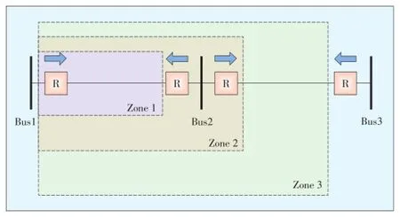
▲Figure 1.Distance protection relays:zone 1,zone 2,and zone 3.
Distance protection relays are one of the most common relays used for power transmission lines[1].The operation of a distance relay is determined by the impedance measured by the relay,which is used to estimate the distance from the relay to a fault.We usually have three protection zones as shown in Fig.1[9].Protection zone 1 is the basic protection of a distance relay,which covers about 80%of the length of a transmission line.The protection zone 2 covers a little more than zone 1,usually about 120%of the length of a transmission line.Protection zone 3 covers the first transmission line and also about 80%of the second line.We can adjust the relay settings for zone 1,zone 2,and zone 3 protection,and construct both primary protection and backup protection with different delays.Normally,we use zone 1 as the primary protection,which is almost immediately triggered when a fault is detected,e.g.,with a delay of a few milliseconds.We use zone 2 and zone 3 protection as backup mechanisms,which are triggered after given tripping delays when a fault is detected.These tripping delays are often determined by the protection distance,e. g.,a zone 2 protection may waits for 0.3 second,and a zone 3 protection may wait up to 1 second[8],[9].
Hidden failures have been considered one of the main sources of large scale disturbances[3],[5],[15].A hidden failure occurs when incorrect system states or control actions are triggered by another system event.It may induce widespread cascading failures such as the Northeastern blackout in 2003,which is initialized by a false relay trip[16].Although solutions to hidden failures on traditional power systems have been extensively investigated[4],[7],[9],it is still extremely challenging to completely prevent such failures on large-scale complicated power systems.
The false trips of zone 3 relays are often associated with hidden failures[7],as shown in the past events.Such false trips have been identified among the main causes of blackouts(about 70%[3],[6]).In the meantime,zone 3 protection is also considered essential to power systems and we really rely on such protection in many cases[1],[2].To deal with such false trips,new agent-based solutions have been proposed by utilizing smart grid communication networks[8],[9].
SG is in rapid development due to its salient features such as improving efficiency and reliability,better utilizing renewable energy,etc[10],[11],[17]-[19].One key difference between the SG and the traditional power systems is that SG enables two-way power transmission with intelligent devices that exploit the rapid increase of computing power and the ubiquitous network communication systems.Many SG technologies have developed and many more new SG applications are still in development,e.g.,Phasor Measurement Unit(PMU)technology[12].
Agent-based protection methods use a query-response model to avoid zone 3 false trips.A software agent is deployed at each relay.When a zone 3 relay r detects a remote disturbance from a line l,it will send a query to a master agent(MA)to verify if such a disturbance has been seen by other relays associated with the same transmission line.The MA then queries all related relays to pull their readings.After the MA receives all responses from these relays,it can determine if the disturbance on line l is a real fault or simply a temporary error.The MA sends a response to relay r to tell it how to react.Ideally,sucha solution can eliminate all over-sensitive tripping of zone 3 relays,assuming that there is only one transmission line error in the system and the query-response process can be completed before relay r is tripped based on its setting.However,the network delay requirement may be violated in real networks. Therefore,we have to consider practical network issues to further improve the reliability of zone 3 protection.
As we focus on the issues on SG communication network,the proposed solution in the following section will also help many other real-time SG applications depending on the same communication network.
3 Proposed Power-Aware Reliable Scheme
In this section,before we discuss the power-aware approach,we will first present an improved two-step network resource management scheme to ensure the message can be exchanged between a relay and its MA in time.We will first introduce the enhanced primary path construction in section 3.1,and present different backup methods in section 3.2 to further improve the communication reliability,in the case that the primary path fails due to unexpected network errors.Then,we will present a power-aware resource management frame-work to improve system reliability and resource management efficiency.
3.1 Enhanced Primary Path Selection with Reliability
To ensure a message is delivered on time between a MA and a relay,we first need deal with network delays for the agentbased protection scheme.Assume the MA is placed on a network topology based on certain criteria(which are out of scope of this paper).Our first task is to build a path for each remote protection relay to communicate with the MA.We name such a path as a Primary Path,and assume no links on this path fails. In our previous work,we proposed to use a shortest path based on the network topology as a primary path[14],which is more efficient in bandwidth use.In this paper,we further improve this process using the most reliable path,which emphasizes the path reliability.The shortest-path method minimizes the distance of a relay/bus to the MA so that a packet may have less resource requirement on each communication link;the most-reliable-path method minimizes the failure probability of a primary path by considering the reliability of its links.
Note that each bus may be associated with multiple relays. In general,only one relay at the bus will experience disturbances at a time and need to contact with the MA for guidance. So we usually only need one path from a bus to the MA.
As a single link failure is one of the most common cases in a network,the failure probability of a primary path is defined as:

where pathiis a primary path from bus i to the MA,and Pf(linkn)is the failure probability of link n.The enhanced primary path selection process is shown in Algorithm 1.
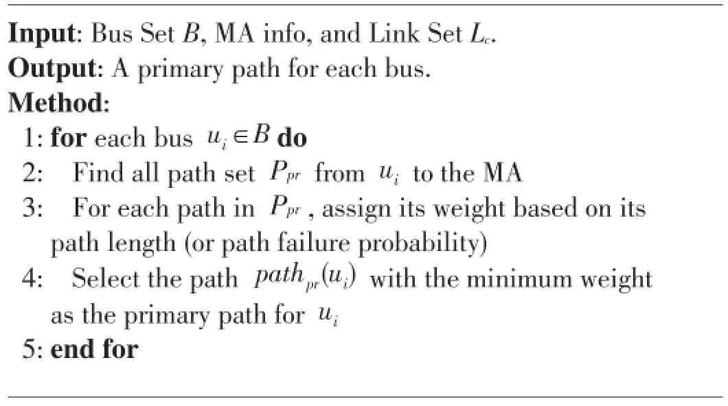
Algorithm 1 Primary path selection algorithm for buses
After finding a primary path for a remote relay,we need to determine its path delay requirement.The agent-based method has four main steps introducing delays:1)A query is sent from a remote relay r to the MA,when it sees a temporary issue(e. g.,a voltage surge or an impedance drop);2)After the MA receives the query from r,the MA queries other related relays,where Rl is the set of relays{r':r'∈Rlandr'≠r},where Rlis the set of relays protecting the same power line;3)A response is sent from each r'to the MA;4)the MA makes a decision based on the responses and sends its decision to r.The maximum allowable delay for a remote relay between sending a query and receiving a decision from MA can not exceed a given amount[8],[9];otherwise,the relay will automatically trip a power line.
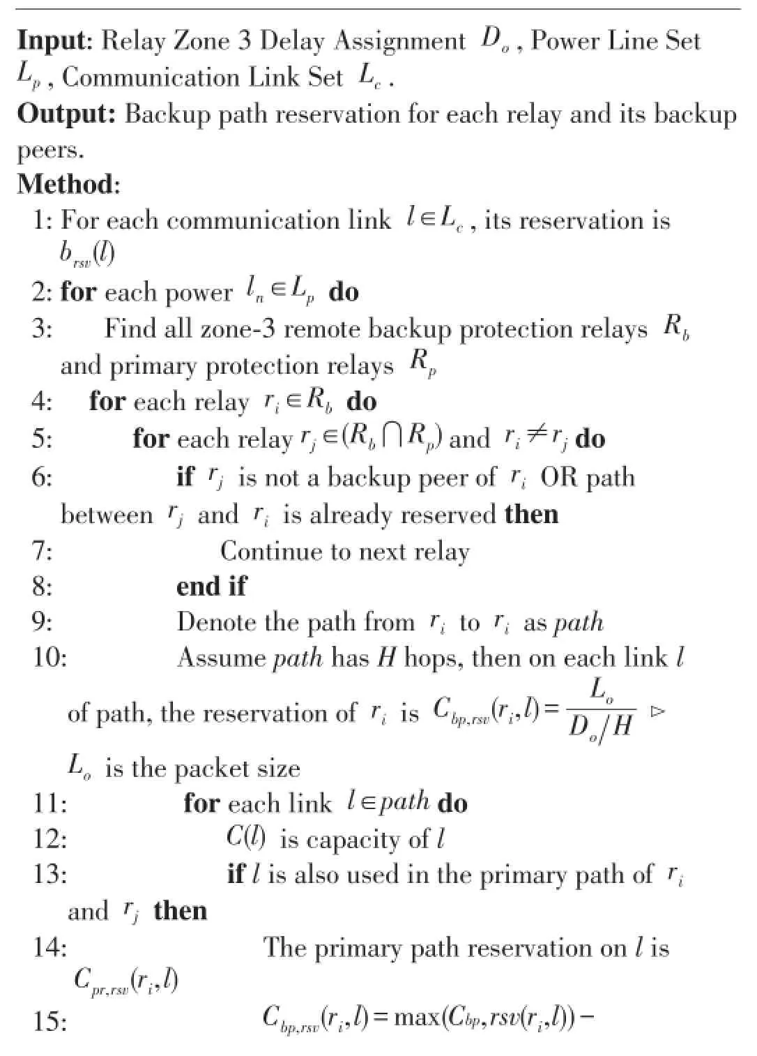
We determine the path delay requirement from a relay to the MA based on the following procedure.Denote the set of power transmission lines as Lp.For a power linel∈Lp,we find two relays r1and r2in Rl,which have the largest and the second-largest hop count hr1and hr2to the MA,respectively.The delay requirement of a remote relay is initialized to a default value D0.(For ease of illustration,we assume that all remote relays have the same delay requirement.In real systems,the requirement of each relay may be different;we can represent them as D0(ri)for relayri.)To ensure the delay requirement in the remote protection procedure,we proportionally divide the total delay requirement between these two relays:in case that one is the remote relay starting the query process and another is among the relays that respond to the MA.That is,the delay requirement between r1and the MA is set to d1=hr1·D0/2(hr1+hr2);the delay requirement between r2and the MA is set tod2=hr2·D0/2(hr1+hr2).For other remote relays of l,their round trip delay requirements are set as no larger than d2,because their path lengths to the MA are equal or smaller than the length from r2to the MA.There is no need to make the other relays to respond faster than r1and r2.(As a relay may be used to protect multiple different lines,it may have different settings.In general,we use the minimal setting of a relay as its preset delay for remote protection.)The delay requirement of a relay is then equally divided along links of itsprimary path and we then reserve resources on each link,as shown in Algorithm 2.
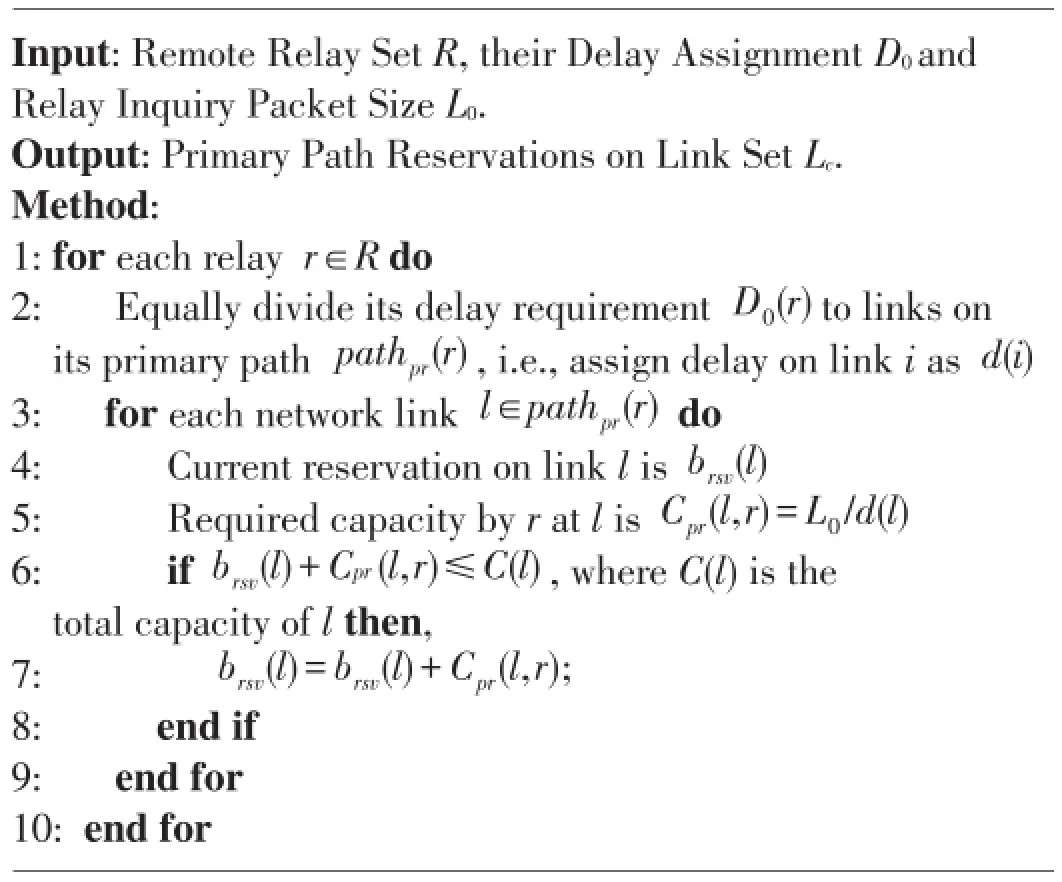
Algorithm 2 Primary path bandwidth reservation algorithm
3.2 Enhancing Backup Path for More Reliability
Without network link failures,a primary path is able to handle the query process.However,in practical networks,links may fail.We need to deal with such failures for remote relay protection.As a single link failure is the most common case,we can handle it by using a backup path that is completely not overlapping with the primary path.However,there are several limitations in this scheme:1)the network topology may not have another path that is a completely not overlapping with the primary path of some buses.2)the length of a non-overlap backup path is often relatively long:for a fixed path delay,a longer path means a short delay and more bandwidth use at each link on the path,which is inefficient and may create unnecessary hot spots in the network.3)a link on a non-overlap backup paths may not have enough capacity to support the backup requirement.
The first and the second limitation can only be fixed by changing network topology,which is out of scope of this paper. Here we focus on the third limitation and we propose to utilize power system information to select backup paths and manage resources more effectively.Assume we have historical data about a power network.Therefore,we know which power line carries more load and how likely it may fail,and we can assign a priority to each power line.Using such information,we can then decide how to allocate the limited network resources to maximize the system reliability.In this paper,we do not have such information available.We then use PowerWorld Simulator to generate such information as presented in the evaluation section.
Based on such known information of power systems,we use Pf(S|linei)to denote the probability that tripping a power line leads to a system failure in simulation.As such data give us the importance of power lines,we can prioritize them in protection.Assume there are Nllines that may result in system failures.We equally divide the total system requirementPSfto these Nllines.In this way,we expect the probabilitydoes not exceedfor each of them.From(2)

Consider that the failure of a line is usually due to the false trip of a relay at one of the two ends of the line.Then we can equally divide the requirement ofPf(linei)to the relays at two ends of the line.For a remote protection relay,when it sees a temporary issue,it sends an query to the MA and waits for the MA's response.If the query cannot reach the MA or the decision from the MA cannot be received by the relay within the required time,a false trip may happen.This case occurs if both a primary path and its backup path of a relay fail at the same time.Under the single link failure assumption,this only happens if the failed link is used by both path.We can define the probability as: where Nolis the set of overlap links between the primary and backup path of the relay.Thus our goal is to find a backup path that hasand can meet the minimum requirement ofPrelayfalsetrip.(Similar to finding a primary path,we find a backup path for a bus,instead for its relays.)The backup path selection procedure is presented in Algorithm 3.After a backup path is selected,resources are also reserved on the path,as shown in Algorithm 4.In case that a link does not have enough capacity to support all backup paths on it,the reservations are carried out with a specified order.For powerlines that may blackout the system,their remote relays are“critical”and will be first considered.If a line is not expected to crash the system,we consider the consequence of tripping this line less important.The goal is to ensure that we can fulfill“critical”relays' requirement as much as possible.

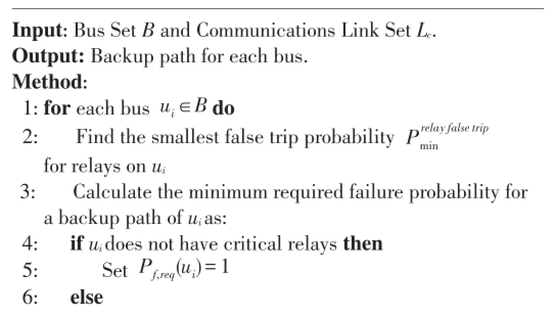
Algorithm 3 Backup path selection algorithm for buses

7:Pf,req(ui)=Prelay false trip min 8:end if 9:Find all backup paths setPbpto MA that are different from the primary path 10:Sort paths inpbpbased on hop count in an ascending order 11:Start from the first path inPbp12:for each backup pathp∈Pbpdo 13:Compute the overlap link setNolbetween ui's primary path and p,then CalculatePtheoverlaplinksf 14:ifPthe overlap links ≤Pf,req(ui)then 15:Select pathpas the backup path 16:end if 17:end for 18:end for f
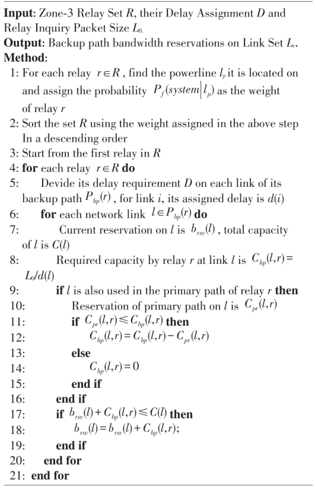
Algorithm 4 Backup path bandwidth reservation algorithm for remote protection relays
Usually a bus contains more than one remote protection relays.We observe that many of the relays are used to protect different power lines.From this observation,we notice that it is possible to further reduce the required network resources,and we will discuss this issue in the evaluation section.
4 Peer-to-Peer(P2P)Protection Scheme for More Reliability
4.1 Motivation:MA is a Single Point of Failure
In the master-based relay protection,the MA receives a query from a substation relay and makes a decision based on system states whether the relay should trip or not,and then sends the decision back to the inquiry relay.Under normal network conditions,this mechanism works properly.However,as the MA is the only node responsible for making decisions,if it is shut down due to cyber-attacks or physical damages,the entire power system will lose the centralized protection,and relays may trip and cause unforeseen instability in the system.
As modern relays are powerful devices,we propose to use a P2P mechanism to deal with the potential unavailability of MA.The key observation is that a relay usually only need to check with a small group of related relays to protect a line.In this scheme,a relay at a substation communicates with other related relays about the state of local and remote power lines. With these responses,the relay can make a justified decision by itself whether to trip or not.An obvious advantage of this scheme is that the average response delay is much shorter than the master-based scheme,because a relay usually only asks other relays nearby,much closer than the MA.(This advantage may be elaborated when a relay need to make a very quick decision for special cases,even when the MA is still available.)
4.2 Proposed P2P Protection Procedure
Identify related relays and form a peer group.For each transmission line,we need first identify the set of related primary and remote relays for a power line and form a relay peer group for the line,shown in Algorithm 5.will trip the line when its primary relay fails to do so;otherwise,it assume no fault.
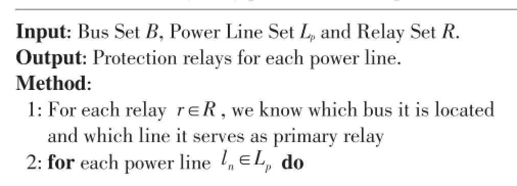
Algorithm 5 Identify relay protection set for power lines
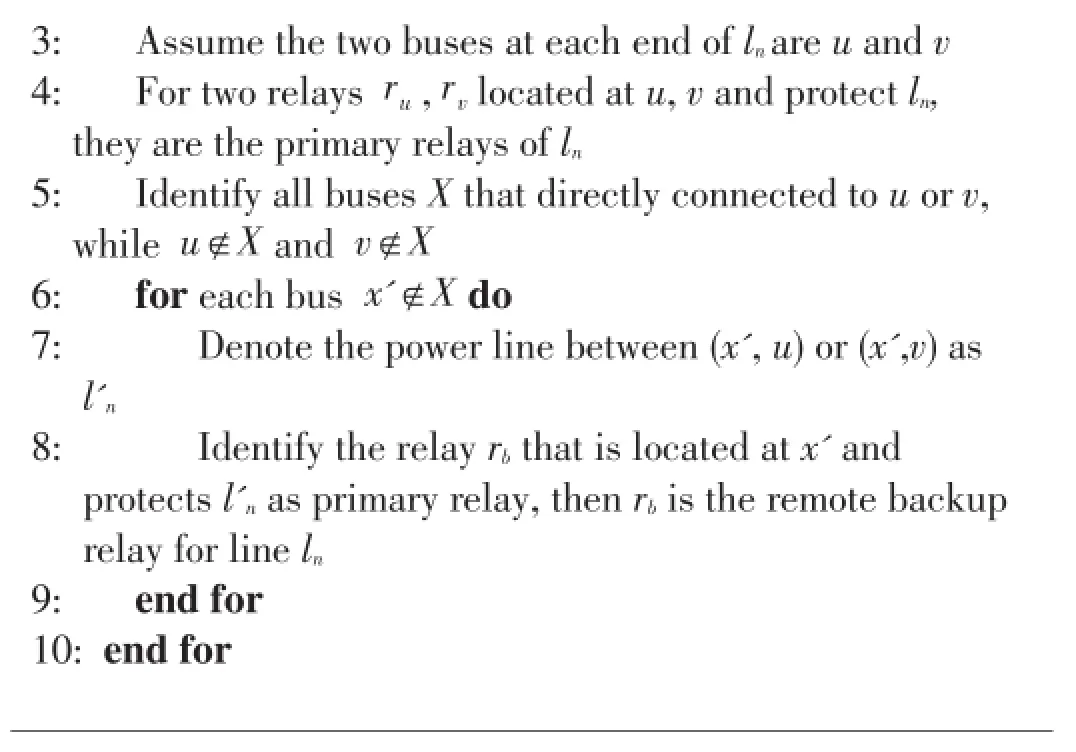
3:Assume the two buses at each end of lnare u and v 4:For two relaysru,rvlocated at u,v and protect ln,they are the primary relays of ln5:Identify all buses X that directly connected to u or v,whileu∉Xandv∉X 6:for each busx'∉Xdo 7:Denote the power line between(x',u)or(x',v)as l'n8:Identify the relay rbthat is located at x'and protects l'nas primary relay,then rbis the remote backup relay for line ln9:end for 10:end for
The primary path selection and resource reservation on each link of a path is shown in Algorithm 6.We have the following assumptions here.1)A relay will communicate with all other related peers.2)At one moment,there is only one hidden failure exposed[9],e.g.,one relay has abnormal reading.Moreover,if there is only one hidden failure in the system,a single response from a peer is sufficient to make the decision.3)At this step,the effect of link failure to the protection is not considered;and we will discuss backup schemes in the following. With the proposed P2P scheme,even if the master agent is shutdown unexpectedly,relays in the system are still able to make correct decisions to prevent the false trips of power lines.
We give an example in Fig.2,for Line2,r3and r4are the primary relays and(r1,r5,r8,r10)are the remote protection relays. If any remote relay of this set sees a disturbance,it will check with one or more other relays within this set.
When the inquiry relay receives replies from other peers,it uses a voting scheme to decide the action.
For example,if relays with positive confirmations outnumber relays that do not see the fault,the inquiry relay will assume that there is a“real-fault”in the transmission line,and

▲Figure 2.The power system can be divided into different protection areas with the corresponding sets of relays.
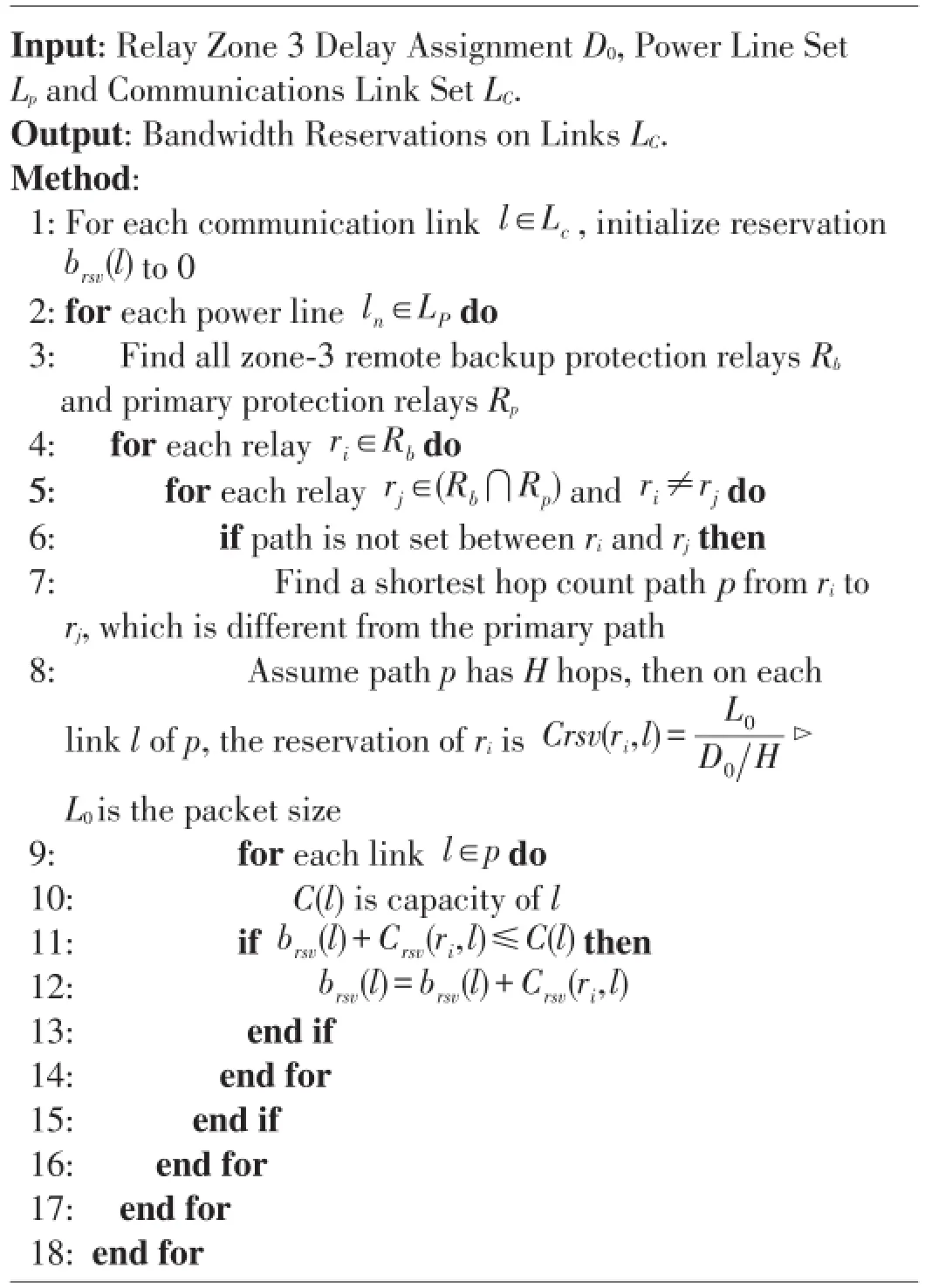
Algorithm 6 Primary path selection and bandwidth reservation algorithm for P2P scheme
In the P2P scheme,we have two types of delays:1)the(maximum)delay to send a query to other related relays,and 2)the(maximum)delay for other relays to send their responses back to the inquiry relay.The round trip delay should not exceed a pre-defined time period D0to avoid false trips.To make sure the decision can be made within the required time period D0,we need to reserve network resources for a path from a relay to another relay.The relay delay requirement to and from a peer relay can be set to D0/2.Assume the path consists of H hops and each inquiry has size L0,the required resource on each link isL0/(D0/2)/H).
As in the master-based scheme,the P2P scheme can also use backup paths to deal with communication link failures.Unlike the master-based scheme where the reservation is required between each bus and the master agent,in the P2P scheme,we can reduce the network usage by answering the following questions:1)Does the P2P scheme need to backup for all of its primary paths between relays?2)For the backup path used in the P2P scheme,whether to use overlapped or nonoverlapped paths?For the first question,we consider that a minimum of two replies may be enough for the inquiry relay to make a majority decision,given the fact that two relays have hidden failures simultaneously is very low[9].In addition,in[20],it is considered that,if the system is not in a“stressed state”,which means the system is not close to unstable operational condition,a relay can even make decision without the responses from other relays.For the second question,due to the specific topology of a system,non-overlap paths can be much longer than the normal paths,especially for the P2P scheme in which primary paths are mostly just a few hops.As an alternative,overlapping backup paths may be used if we can still meet the system requirement.The advantage is obvious:overlapping paths are shorter,thus consume less network resources at each link.The backup path selection process and the resource reservation process are shown in Algorithm 7 and Algorithm 8.Note that since some relays are protecting multiple lines,for example,riand rjprotect linekand linelsimultaneously,then they can both be used as a backup protection relay pair for the two lines.In this way,when we protect linekwith riand rj,we only need to find one additional backup path for protecting linel,which save resources instead of using two different backup paths.

Algorithm 7 Backup path selection algorithm for P2P scheme

backup paths already found,asRx,its size isNx8:ifNx≥Nuthen 9:Continue to next relay inRb10:else 11:We still need to findN'i=Nu-Nxnumber of backup peers 12:end if 13:for relayrjinRxdo 14:ExcluderjfromR'i⊳We already have backup path torj15:end for 16:FindN'inumber of peers fromR'i,which have the shortest hop count paths as the backup peers ofri⊳The paths between each of the found relay andrishould be different from their primary paths,they can have overlapped links with the primary paths or be totally non-overlapped 17:end for 18:end for
Algorithm 8 Backup path bandwidth reservation algorithm for P2P scheme

?
We can compute the failure probability of a power system,Pf(S),as shown in(5)to(7).We assume that the false trips of one critical line will result in a system failure,and there are different critical lines under different system load states.The total failure probability of the system is the sum of probability{system fails and lineifails}.Then,based on the known historical information of a power system,we usePf(S|linei)to denote the conditional probability that tripping a power line leads to a system failure in simulation.With the above data given,the Pf(S⋂linei)will be determined by the probability that a power line is falsely tripped,denoted asPf(linei).As we have mentioned before,the malfunction of zone 3 remote relay is a common reason for false trips.With the deployment of agent-based protection,under normal conditions,we can deal with such potential malfunctions.However,the failure still exists if either of the primary relays on a power line cannot obtain correct responses from the MA or other peers.Thus,the probability directly relates to the false trip probability of a relay,Prelayfalsetrip,as in(7),where relayi,1and relayi,2are the two relays at each end of linei(assume each time only one relay is exposed to a hidden failure).We will see that different primary and backup paths selection will affect the false trip probability of a relay as shown in the evaluation section.

5 Performance Evaluation
5.1 Evaluation System Setting
We evaluate the proposed schemes on the IEEE 39-bus system[9].We simply assign the MA at bus 16 because the maximum hop count from bus 16 to other buses is the minimum among all buses,and it also has the highest connection degree in the system.(More sophisticated MA assignment schemes need detailed power system and communication network information,which is out of the scope of this paper.)For testing purposes,to make every bus have a non-overlap path for comparison,we modify the topology slightly by adding a communication link between bus 19 and bus 21.Assume bus 21 is the closest bus for bus 19.Assume all query and response packets have the same size of 80 bytes,e.g.,a simple PMU packet.We set the system failure requirement to10-5,which is a higher requirement than current power grid[24],and set the communication link capacity to 1.5 Mbps(one T1 line)[25]with a failure probability no more thanPf(link)=10-5[26].In this case,the probability of two or more links fail simultaneously is about 10-8,which is much smaller than the system requirement. Thus,in this paper,we only consider a single link failure.
To build power system knowledge,we use the PowerWorld simulator[21]to obtain the conditional probabilityPf(S|linei). As we know,more reactive loads cause more system losses,and result in various instability issues which may lead to system failures.We follow the methods used in[22],[23],and gradually increase the reactive loads of all PQ buses that have nonzero reactive loads,by setting loadnew=loadbase·(1+x).The increase step of x is 10%of the base load each time.At each system load setting,we examine system contingency by tripping power transmission lines one by one to check if the system fails(shown as a blackout in Power World).We vary x in a range of(0;3.3),because a blackout usually happens when x≥3.4,even if we do not trip any line.As a result,we haveequals to 1 if a system failure happens;otherwise,it is 0.For lineiwhose tripping may cause system failures,we obtain its Pf(S|linei)based on the above procedure,associated with 15 lines ranging from 0.8%to 4.2%.We use these data for optimizing backup path selection later.
5.2 Performance of Primary Selections and Backup Paths without/with Power Knowledge
To evaluate the two primary path schemes and corresponding backup path schemes,we assign the failure probability of a communication link according to the amount of transmitted power on the corresponding power line.(Assume each communication link connects the same buses as its power line.)For lines with more than 200 MW power(in 39-bus system,under normal condition,we have 17 lines with real power more than 200 MW,which is about 50%of all power lines),we set their corresponding links with Pf(link)=10-6;otherwise,Pf(link)=10-5.As shown in Table 1,when using primary paths only,neither primary selection scheme alone can achieve the system requirement(10-6),as shown in the first row.The reliability-based primary-path selection does a little better than the shortest path selection.After adding backup paths,both schemes can fulfill the system requirement and achieve similar system reliability,as shown in the second row.
Using power knowledge can improve system reliability.As discussed in Section 3,we can handle a single link failure on a primary path by using a completely non-overlap backup pathfor each relay as a topology-based backup selection.However,this method consumes more resources.We utilize power system knowledge to address this issue.As mentioned before,we observe 15 lines that may lead to system failures under different load settings.Therefore,we prioritize these lines and their protection relays to better use network resources.Here we set Pf(link)=10-5for all links.Compared with using complete non -overlap backup paths,such a power-aware backup path selection significantly reduces the bandwidth reservation on almost every link,and the average bandwidth saving across all links is about 18%.The upper two curves in Fig.3 show the comparison of reservations on links.We sort them from high to low for easy illustration.In the above,we compare the maximum required link reservation on the 39-bus system for using nonoverlap backup paths and partially overlapped backup paths with the system failure requirementRS=10-6.To further show how the proposed power aware scheme can reduce link reservations,we also test it with system failure requirement RS=10-5.

▼Table 1.Comparison of system reliability
Assume the single link fails withPf(link)=10-5.As shown in Table 2,compared with the non-overlap path scheme,the power-aware scheme can significantly reduce bandwidth reservation(29%less)while still meeting the system reliability requirement.In the second row,we set the value of non-overlap path scheme as the“base”of 100%.
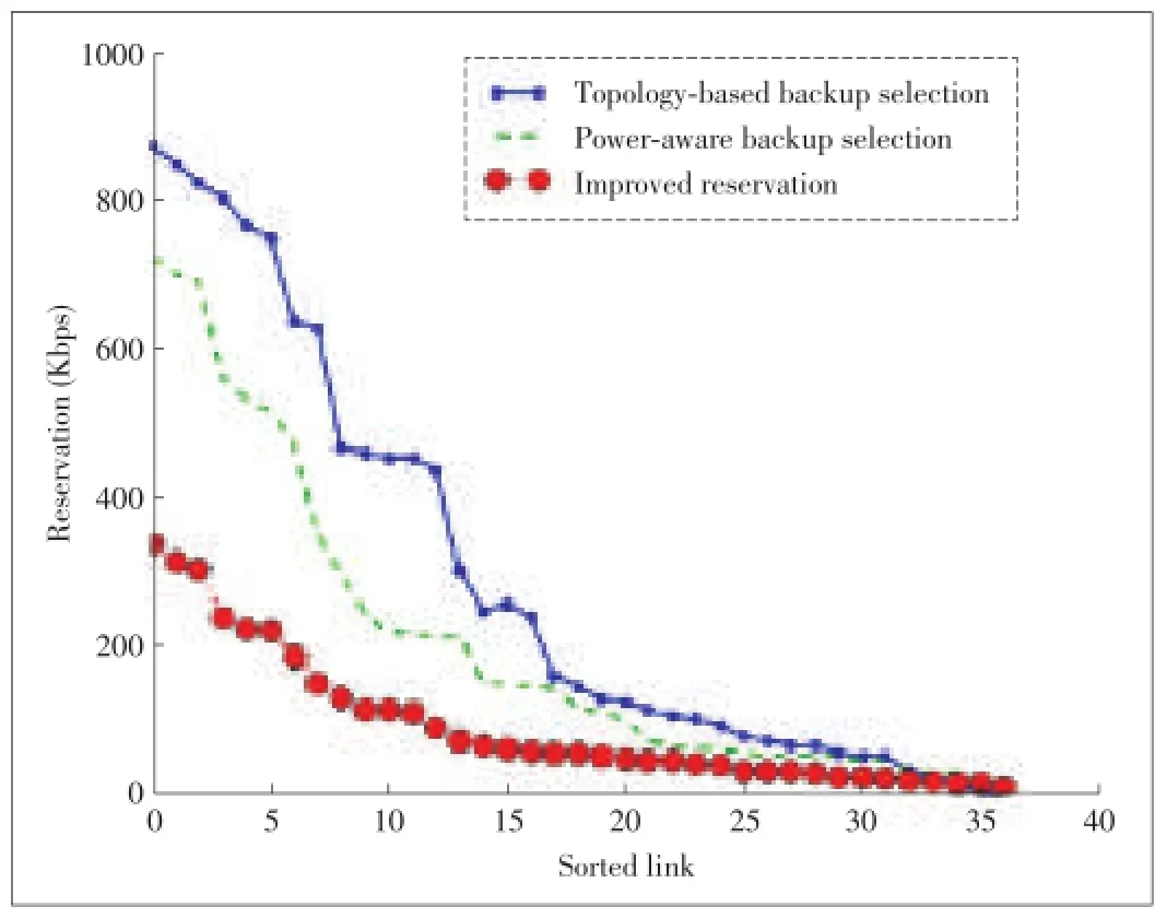
▲Figure 3.Backup path selection with/without power knowledge and improved reservation scheme.

▼Table 2.Comparison of maximum link reservation for different backup path schemes and requirements
When some links do not have enough capacity,we assign higher priorities to the protection relays of important lines based on the power knowledge to further improve the system reliability.We compare three simple resource reservation orders in the following.The first order is to start to allocate bandwidth from the most important relay to least important one;the second order use the opposite order for comparison;the third order is to allocate bandwidth using random bus orders(here we compute the average of 20 random orders).To show the case that some relays may not obtain the required bandwidth on a link,we make link 19 as the bottleneck and reduce its capacity from 1.5 Mbps to 550 Kbps.We set the system requirement as10-6,and the failure probability of links as10-5.We observed that the relays without enough reservation vary in the different orders.For the latter two orders,some relays do not obtain enough bandwidth for their paths,for example,relays protecting Line{3,5,6,15,19,21,31}.However,these lines have higher probabilities in causing system failures if improperly tripped.The system failure probabilities for different orders are1×10-7,1.5×10-6,and6.7×10-7respectively.
Smart Reservation.A bus may have multiple remote relays for protecting different power lines.In common cases,they will not simultaneously communicate with the MA.This provides us another opportunity to further reduce the required bandwidth on communication links.Assume only one relay experiences a hidden failure or only one power line has disturbances. For example,in the IEEE 39-bus system,only bus 26,28,and 29 have two remote relays protecting the same line;remote relays on other buses all protect different power lines.In this case,we only need to reserve bandwidth for relay riwith the most strict delay requirement on a bus.Because other relays on that bus do not have delay requirement as high as ri,the reserved capacity is sufficient for them to communicate with the MA.Again,we set the system requirement as10-6and Pf(link)=10-5.The maximum required capacity on a link decreases from 725 Kbps to 366 Kbps,a nearly 50%saving.As shown in Fig.3,comparing the lower two curves,on average,we save about 39%capacity on each communication link.The overall system failure probability is1×10-7,still meeting the system reliability requirement.
5.3 Comparing Master-Agent-Based and P2P Schemes
We follow the method in[9],assume at a single moment,there is only one hidden failure exposed in the system:a disturbance is applied to a power line that the relay with a hidden failure will sense the disturbance,and the communication network has a single link failure at most.We compare the resource requirement for the protection and the false trip proba-bility of each relay,under four schemes:the MA scheme without backup paths,the P2P scheme without backup paths,the MA scheme with backup paths,and the P2P with backup paths.For the primary path selection,both the MA scheme and the P2P scheme use the shortest path to the master node or peers.For the backup path selection,both schemes use nonoverlap backup paths.
The result for resource requirement is shown in Fig.4.Without backup paths,the P2P scheme consumes the minimum resources since the distance to peers are shorter than in the MA scheme.However,adding backup paths to both schemes significantly increases the resource usage.Fig.5 shows the false trip probability of each relay in the system.Under the single link failure condition,in the MA scheme without backup paths,if the primary path of a relay fails,it cannot communicate with the MA and will result in a false trip.As we can see,more relays in the MA scheme are affected than in the P2P scheme,For the P2P scheme,since each peer can send its response to the inquiry relay,the false trip occurs if all paths to the relay's peers fail,which means the failed link is shared by all paths to the peers.Intuitively,this probability is much lower than the failure of a primary path in the MA scheme.With non-overlap backup paths,both the MA scheme and the P2P scheme can handle a single link failure,in which all relays have zero failure probability.Combining the relay false trip probability with the power data(Pf(S|linei),the system failure probability can be computed.
Without backup paths,the system reliabilityPf(S)in the P2P scheme is0.55×10-6,which is about 4-time better than that of the MA scheme(2.62×10⁻⁶).Note that the P2P scheme can meet the 10-6requirement but the MA scheme cannot.This matches the results from Fig.5 that the failure of a primary path of a relay has more influence in the MA scheme,because all relays must first contact the MA and then receive a decision from the MA.While we can protect relays from false trips using non-overlap backup paths,judging from the resource requirement from Fig.4,the cost of non-overlap backup path in the two schemes do not have much difference.The potential difference between the two is the response delay.

▲Figure 4.Resource requirement for different protection schemes with/without backup path.
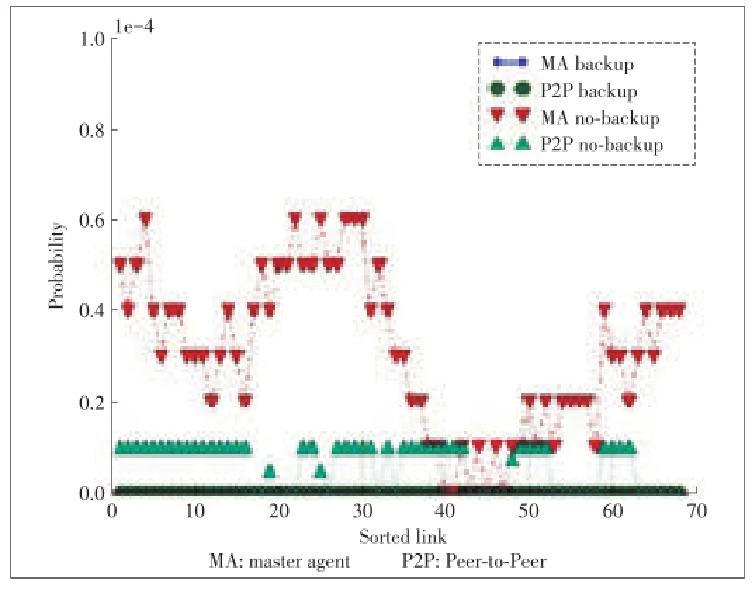
▲Figure 5.False trip probability of each relay,assume a single link failure.
The response delay counts from the time when the query is sent until a decision reaches the inquiry relay.This delay is closely related to the path distance(hop count),especially when the traffic load is light most of the time.We compute the maximum,minimum and average hop counts for both the MA scheme and the P2P scheme.For the MA scheme,the primary/ backup path distance is between a bus and the MA bus.The result for the MA scheme with non-overlap backup paths is shown in Table.3.As a comparison,the result of the P2P scheme with non-overlap backup paths is also given.In the P2P scheme,paths exist between each pair of“corresponding relays”.Note that in both the MA and P2P schemes,the minimum hop count is 0.The reason is that,in the MA scheme,there are a few relays locating at the same bus with the MA;for the P2P scheme,in the 39-bus system,relays(64,67)and relays(66,68)are located at bus 28 and 29,respectively,and they are protecting the same lines.Thus the communication between these relays are within a substation.(We assume the indexes of relays for a power transmission line with index i are 2·iand2·i-1.).In addition,although the average path length between(the MA and a non-MA bus)or(P2P peers)are similar,in the MA scheme the query process takes two roundtrip delays.While in the P2P scheme,there is only one roundtrip delay(as shown in the“Actual”column of Table 3).As link loads are not heavy most of the time,a shorter path benefits the protection with faster response delays.
Compare the effect of full backup vs.partial backup paths and the effect of overlap backup vs.non-overlap backup paths. The above case is the worst case resource requirement for theP2P scheme since a non-overlap path between each pair of“corresponding relays”are reserved.As a comparison,the shortest-hop-count overlap backup path is tested in the P2P scheme.Similar to the non-overlap scheme,resources for each“corresponding relay pair”is reserved as well.We exam the“stressed case”and assume two replies returning from peers will enable the inquiry relay to make correct decision.

▼Table 3.Path hop count in the MA scheme
Fig.6 shows network resource requirements for each protection scheme.
Fig.7 shows the false trip probability of relays.We see that only four out of about 68 relays are affected when using overlapping paths.Fig.6 and Fig.7 also show that the resource requirement further decreases because now each relay only reserves for two backup paths.
When using non-overlap backup paths,all relays can handle the single link failure;while using overlapping backup path uses less resources at the cost of a few more potential false trips. Table 4 shows how the total resource requirement and the changes of system reliability for different backup schemes.
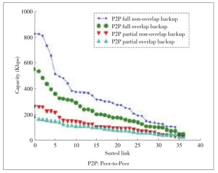
▲Figure 6.Resource requirement for P2P schemes with/without backup path for each relay.

▲Figure 7.Relay false trip probability for P2P schemes with/without backup path for each relay,assume a single link failure.

▼Table 4.Total resource requirement and system failure probability with/without backup path for each relay
Compare the effect of the number of overlapping backup paths in the P2P scheme.We try to identify how many overlapping backup paths should be used in the P2P scheme by varying the number of backup paths for each relay from two to five. We choose the shortest hop count path as a backup path,and allow this path to have overlapping links with its primary P2P path.The results are summarized in Table.5,including the total resource requirement,the overall failure probability of the system,number of potential relay failure,and average relay failure probability.As we can see,the more backup path we use,the less number of relays that will have false trips.The resource requirement is as expected:the more backup paths we use,the more resources we consume.Comparing the first two lines of Table 5,a significant point is that,when we increase the number of overlap backup paths from two to five,the resource cost doubles,but the reliability is improved by tenfolds.While the trends of improvement are different in in the second and forth lines,the reason is that power lines are not of the same importance:for some lines,the false trip may lead to severe system failure,while others are not.
6 Conclusions and Future Work
In this paper,we have developed more reliable remote relay protection schemes by exploring both network link reliability and power systems knowledge on SG.Furthermore,to address the single point of failure of common centralized control center,we have also investigated P2P protection approaches.The simulation results show that the proposed method can significantly improve power system reliability while utilizing network resource more effectively.
In this paper,as most existing research,we assume that acascading failure starts at a single line,which leads to the sequential trips of neighbor lines.However,recent research[27]demonstrated that this sequence is not easily characterized and may be geographically separated,i.e.,the cascading does not necessarily develop in a contiguous manner.Our future investigation will focus on this new direction.Although the agentbased scheme is helpful in preventing the cascading failure,we notice that it also has the potential to mitigate the damage of already on-going cascading,e.g.,by tripping certain lines in advance.The foundation of such schemes is reliable real-time network communications,from collecting system states to accurate transmission of decisions to each critical location.
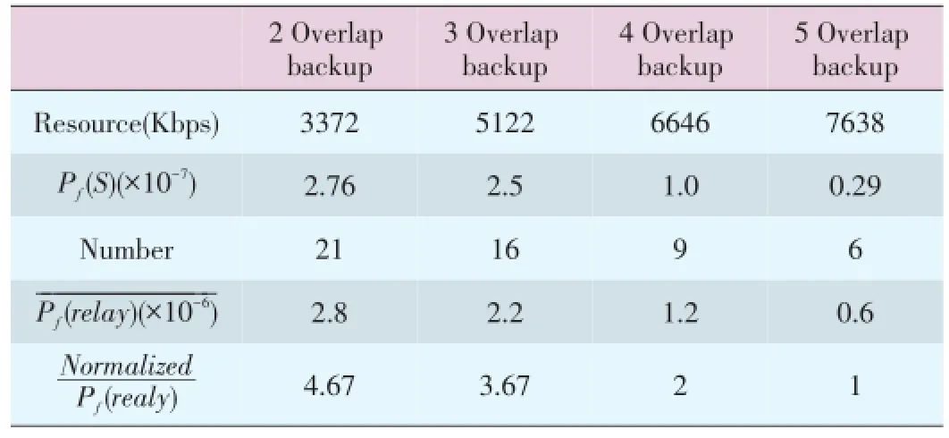
▼Table 5.Total resource requirement,System failure probability,and Number of potential failure relay and their average failure probability under different P2P schemes
[1]S.H.Horowitz and A.G.Phadke,“Third zone revisited,”IEEE Transactions on Power Delivery,vol.21,no.1,Jan.2006,pp.23-29.doi:10.1109/TPWRD.2005.860244.
[2]NERC.Rationale for the use of local and remote(zone 3)protective relaying backup systems[Online].Available:http://www.nerc.com/docs/pc/spctf/Zone3Final. pdf,2005.
[3]D.Novosel,M.Begovic,and V.Madan,“Shedding light on blackouts,”IEEE Power and Energy Magazine,vol.2,no.1,Jan.2004,pp.32-43.doi:10.1109/ MPAE.2004.1263414.
[4]D.C.E.de la Garza,“Hidden failures in protection systems and its impact on power system wide-area disturbances,”M.S thesis,Virginia Polytechnic Institute and State University,2000.
[5]J.S.Thorp,A.G.Phadke,S.H.Horowitz,and S.Tamronglak,“Anatomy of power system disturbances:Importance sampling,”International Journal of Electrical Power and Energy Systems,vol.20,no.2,pp.147-152,Feb.1998.
[6]J.S.Thorp and A.G.Phadke,“Protecting power systems in the post restructuring era,”Computer Applications in Power,IEEE,vol.12,no.1,pp.33-37,1999.
[7]H.Wang and J.S.Thorp,“Optimal locations for protection system enhancement: A simulation of cascading outages,”IEEE Transactions on Power Delivery,vol. 16,no.4,Oct.2001,pp.67.doi:10.1109/MPER.2001.4311473.
[8]S.Garlapati,H.Lin,S.Sambamoorthy,S.K.Shukla,and J.S.Thorp,“Agent based supervision of zone 3 relays to prevent hidden failure based Tripping,”In 2010 First IEEE International Conference on Smart Grid Communications,Miami,USA,2010,pp.256-261.
[9]H.Lin,“Communication Infrastructure for the Smart Grid:Co-Simulation Based Study on Techniques to Improve the Power Transmission System Functions with Efficient Data Networks,”PhD thesis,Virginia Polytechnic Institute and State University,2012.
[10]X.Fang,S.Misra,G.Xue,and D.Yang.Smart grid-the new and improved power grid:A survey[Online].Available:http://citeseerx.ist.psu.edu/viewdoc/ summary?doi=10.1.1.387.3141
[11]W.Wang,Y.Xu,and M.Khanna,“Survey paper:A survey on the communication architectures in smart grid,”Computer Network,vol.55,no.15,October 2011,pp.3604-3629.doi:10.1016/j.comnet.2011.07.010.
[12]D.E.Bakken,B.Anjan,C.H.Hauser,D.E.Whitehead,and G.C.Zweigle,“Smart generation and transmission with coherent,real-time Data,”Proceedings of IEEE,vol.99,no.6,pp.928-951,2011.doi:10.1109/ JPROC.2011.2116110.
[13]J.Gao,Y.Xiao,J.Liu,W.Liang,and C.L.P.Chen,“A survey of communication/networking in smart grids,”Future Generation Computer Systems,vol.28,no.2,pp.391-404,2012.
[14]J.Zhang and Y.Dong,“Preventing false trips of zone 3 protection relays in smart grid,”TSINGHUA Science and Technology,vol.20,no.2,pp.142-154,2015.
[15]J.Chen,J.S.Thorp,and I.Dobson,“Cascading dynamics and mitigation assessment in power system disturbances via a hidden failure model,”International Journal of Electrical Power&Energy Systems,vol.27,no.4,pp.318-326,2005.
[16]U.S.-Canada Power System Outage Task Force,“Final report on the august 14,2003 blackout in the united states and canada:Causes and recommendations,”2004.
[17]H.Farhangi,“The path of the smart grid,”IEEE Power and Energy Magazine,vol.8,no.1,2010.doi:10.1109/MPE.2009.934876.
[18]D.E.Bakken,C.H.Hauser,H.Gjermundrød,and A.Bose.Towardsmore flexible and robust data delivery for monitoring and control of the electric power grid[Online].Available:http://www.gridstat.net/TR-GS-009.pdf
[19]J.Liu,Y.Xiao,S.Li,W.Liang,and C.L.Chen,“cyber security and privacy issues in smart grids,”Communications Surveys&Tutorials,IEEE,vol.14,no. 4,pp.981-997,2012.
[20]V.Centeno,J.Thorp,and A.Phadke.Advanced protection system using wide area measurements[Online].Available:http://www.uc-ciee.org/_ucciee68/images/ downloadable content/electric grid/APWA Final Report.pdf,2010
[21]PowerWorld Corporation.Powerworld homepage[Online].Available:http:// www.powerworld.com/
[22]A.Agatep,“Voltage stability analysis using simulated synchrophasor Measurements,”M.S thesis,California Polytechnic State University,2013.
[23]I.Musirin and T.A.Rahman,“On-line voltage stability based contingency ranking using fast voltage stability index(FVSI),”IEEE/PES Transmission and Distribution Conference and Exhibition 2002:Asia Pacifi.,Yokohama,Japan,2002,pp.1118-1123,2002.doi:10.1109/TDC.2002.1177551.
[24]C.Hertzog.Reliability and the smart grid[Online].Available:http://www. smartgridlibrary.com/2010/08/02/reliability-and-the-smart-grid/
[25]R.Hasan,R.Bobba,and H.Khurana,“Analyzing naspinet data flows,”In Power Systems Conference and Exposition(PSCE'09),IEEE/PES,pp.1-6,2009.
[26]S&C Electric Company.Designing a smart grid communication system to achieve 99.999%link availability[Online].Available:http://www.sandc.com/ edocs pdfs/edoc 075041.pdf
[27]A.Bernstein,D.Bienstock,D.Hay,M.Uzunoglu,and G.Zussman,“Power grid vulnerability to geographically correlated failuresanalysis and control implications,”In INFOCOM,2014 Proceedings IEEE,Toronto,Ontario,Canada,2014,pp.2634-2642.
Manuscript received:2015-04-29
Biographies
Jiapeng Zhang(jiapengz@hawaii.edu)received his BS degree in Electronic Information Technology from the Macau University of Science and Technology in 2010 and MS degree in Telecommunication from the Hong Kong University of Science and Technology in 2011.He is currently pursuing his PhD degree in University of Hawaii at Manoa.His research interests are network scheduling,planning,simulation,and smart grid communication.
Yingfei Dong(yingfei@hawaii.edu)received his BS degree and MS degree in computer science at Harbin Institute of Technology,China,in 1989 and 1992,his Doctor degree in engineering at Tsinghua University in 1996,and his PhD degree in computer and information science at the University of Minnesota in 2003.He is currently an associated professor at the Department of Electrical Engineering at the University of Hawaii at Manoa.His current research mostly focuses on computer networks,especially in network security,smart grid communication security,cloud security,real-time networks reliable communications,Internet services,and distributed systems.His work has been published in many referred journals and conferences.He has served as both organizer and program committee member for many IEEE/ ACM/IFIP conferences.He is also serving on several editorial boards for journals on security and networking.His current research is supported by National Science Foundation.
- ZTE Communications的其它文章
- Fast, Exact and Robust Set Operations on Polyhedrons Using Localized Constructive Solid Geometry Trees
- An ImprovedWireless Sensor Network Routing Algorithm
- Crawler for Nodes in the Internet of Things
- A General SDN-Based IoT Framework with NVF Implementation
- Experimental Study on Cloud-Computing-Based Electric Power SCADA System
- Secure Communication Networks in the Advanced Metering Infrastructure of Smart Grid

