
Effect of refilling time on Microstructure and Mechanical properties of friction spot welded LY12 alum inum alloy*
2015-09-05 00:49LiZhengweiJiShudeMaYinanChaiPengandYueYumei李政玮姬书得马轶男岳玉梅
China Welding 2015年1期
Li Zhengwei,Ji Shude,Ma Yinan,Chai Peng and Yue Yumei李政玮,姬书得,马轶男,柴 鹏,岳玉梅**
Effect of refilling time on Microstructure and Mechanical properties of friction spot welded LY12 alum inum alloy*
Li Zhengwei,Ji Shude,Ma Yinan,Chai Peng and Yue Yumei
李政玮,姬书得,马轶男,柴 鹏,岳玉梅**
Friction spot welding(FSpW)was successfully used to produce joints of LY12 alum inum alloy.The effects of refilling time onmicrostructure and mechanical properties of FSpW jointswere systematically studied.Results show that the cross-section of FSpW joint presents a basin-likemorphology.A white bonding ligament exists in the center of the joint.The stir zone can be clarified into sleeve affected zone and pin affected zone based on different grain sizes.With increasing the refilling time from 2.0 s to3.5 s,grains in the stir zonebecome coarser,microhardnessof the joint decreasesand tensile shear failure load of the joint firstly increases and then decreases.Themaximum tensile shear failure load of 8 130 N is attained when the refilling time is3.0 s.Shear-plug fracturemode and shear fracturemode can be observed in the tensile shear tests. Themaximum hardness of169.7 HV isattained in the joint centerwhen the refilling time is2.0 s.
friction spotwelding,refilling time,microstructure,tensile shear failure load
0 Introduction
As a solid-state welding process,friction stir spot welding(FSSW)was invented on basis of friction stir welding(FSW).So far,FSSW has been used in many structures,including the rear door of RX-8 car by Mazda Motor Corporation in 2003[1].Owning the same advantages of superior mechanical properties,lower energy consumption and smaller distortion as FSW[2-3],FSSW is now considered as a promising technology to replace resistance spot welding(RSW),which is the most common spotwelding technology nowadays[4].
However,a keyhole with the same size of the rotational pin inevitably exists in the joint center after FSSW. Keyhole notonly leads toworse corrosion resistance but also induces severe stress concentration when the joint bears external force[5-6].Friction spot welding(FSpW)was developed by GKSS,by which joints without keyhole can be obtained.According to Mazzaferro et al.[7],FSpW can be clarified into pin plunge type and sleeve plunge type. Compared with pin plunge type,sleeve plunge FSpW fabricates joints with larger bonding area,but it requires bigger plunging force at the plunging stage.
Since the invention of FSpW,some investigations have been done to understand the microstructure and mechanical properties of the FSpW joints[8-11].Rosendo et al.[9]performed FSpW experiment on AA6181-T4 aluminum alloy and studied effects of rotational speed and welding time on mechanical properties of the joints in terms of tensile shear failure load and hardness.Shen et al.[10-11]studied effects of welding parameters on defects,tensile shear failure load and microhardness of the FSpW joints of 7075-T6 and 6061-T4 aluminum alloys.However,researches about effect of refilling time on microstructure and mechanical properties of FSpW joints are relatively few.In the present study,FSpW was used to weld LY12 aluminum alloy and effect of refilling time onmicrostructure andmechanical properties of the joints was studied.
1 Experimental
LY12 aluminum alloy was chosen as the research object.Thicknesses of the upper and lower plates were 1.5 mm and 2 mm,respectively.Before welding,all plates were polished with emery paper to clean off the oxide layer.All the specimens were jointed in the center of the lap area,as shown in Fig.1.The RPS100 SK10 FSpW machine was used in the experiment.As illustrated in Fig.2,the tool consists of three parts:a pin,a sleeve and a clamping ring.The outer diameters of pin,sleeve and clamping ring are 5.2 mm,9 mm and 14.5 mm,respectively.Refilling times of 2.0 s,2.5 s,3.0 s and 3.5 s were applied.Other parameters such as rotational speed,sleeve plunge depth and dwell time were 2 000 rpm,1.8 mm and 0.5 s,respectively.

Fig.1 Con figuration and size of lap shear specimen
After welding,metallographic specimens were cut through the joint center,which were polished and etched with Keller's reagent.Metallographic analyses were performed on opticalmicroscopy(GX71).Vickers hardness profilesweremeasured in themiddle location of the upper plate by a HVS-1000 Vickers hardness tester.The distance between adjacent indentations,load and dwell time were 0.5mm,200 g and 10 s,respectively.Tensile shear tests were performed on a RG4300 electronic universal testing machine.Each of the tensile shear failure load was averaged by three specimens.After the tensile shear test,fracture positionsof the jointswere observed by stereoscopic microscope(ZSA403).

Fig.2 Tool used in FSpW experiment
2 Results and discussion
2.1M acrostructure and Microstructure
Fig.3 shows the cross-sections of the FSpW joints welded at different refilling times.Fig.4 and Fig.5 reveal microstructure of the joint.
It can be seen from Fig.3 that keyhole was successfully refilled under all conditions.The macrostructure of the joint shows a basin-like morphology.A white bonding ligament exists in the joint center.Similar to FSW,FSpW joint of LY12 aluminum alloy can be clarified into several regions,including thermal-mechanically affected zone (TMAZ),heataffected zone(HAZ)and stir zone(SZ),as indicated in Fig.4.The material in SZ experiences large strain and strain rate owing to the mechanical stirring.Therefore,dynamic recrystallization happens and fine and equiaxed grains can be observed.Material in TMAZ undergoes moderate frictional heat and the grains are characterized by highly deformed structure.Thematerial of HAZ presents coarser grains,as shown in Fig.4.

Fig.3 Cross-sections of FSpW joints
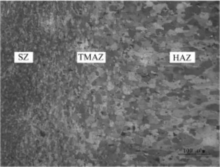
Fig.4 Microstructure of the FSpW joint
During the sleeve plunge FSpW process,material in the joint center is not directly stirred by the rotational tool,which can lead to concentration of the alclad.Therefore,the bonding ligament is thicker in the center.Besides,it should be noted that the SZ can be clarified into pin affected zone and sleeve affected zone.As indicated in Fig.5a and Fig.5b,the grains in pin affected zone are coarser because of insufficient mechanical stirring,which agrees with the bigger thickness of the bonding ligament in the joint center.With increasing the refilling time,more frictional heat is produced,leading to coarser grains of the SZ,as shown in Fig.5c.

Fig.5 Microstructure of pin affected zone and sleeve affected zone on joint welded at different refilling times
2.2 Effect of refilling tim e on tensile shear failure load and fracturem ode
Fig.6 shows the tensile shear failure load of the joints welded at different refilling times.The fracturemodes during the tensile shear tests are revealed in Fig.7.It can be seen that the tensile shear failure load firstly increaseswith increasing the refilling time from 2.0 s to 3.0 s and then decreaseswhen the refilling time increases to 3.5 s.The maximum tensile shear failure load of 8 130 N is attained when the refilling time is 3.0 s.During the tensile shear tests,the shear-plug fracture mode is attained when the refilling time varies from 2.0 s to3.0 s.The shear fracture mode is attained when the refilling time of 3.5 s is used. As shown in Fig.7,fracture position locates at the sleeve retraction path in the shear-plug fracture mode,while in the shear fracturemode,crack propagates along the bonding ligament.

Fig.6 Tensile shear failure loads of the join tswelded at different refilling times

Fig.7 Fracturemodes of the FSpW joints
As is well-known,atom diffusion process is very important for the solid state welding process.At the refilling stage,plastic material is pushed by the pin to refill the cavity left by the sleeve.Then the material in SZ comes into contact with the material in TMAZ at the sleeve retraction path.Therefore,the atom diffusion effects at the sleeve retraction path and lap interface are the key factors to determine the bonding quality of FSpW joints.Bonding strength at these two positions determines the fracture modes of the joints.In fact,atom diffusion effect is greatly influenced by pressure,temperature and time.During FSpW process,lap interface and sleeve retraction path are perpendicular to and parallel to the clamping force,respectively.Therefore,pressure of thematerial at lap interface ismuch bigger than that at the sleeve retraction path. Bigger pressure can accelerate the atom diffusion process. Moreover,the atom diffusion process at the lap interface happens not only at the refilling stage but also at the plunging stage.Compared with the sleeve retraction path,bigger pressure and longer time are both beneficial to the atom diffusion effect at the lap interface.Better bonding strength at the lap interface causes crack more easily to propagate along the sleeve retraction path.This is the reason why shear-plug fracture happens when the refilling time varies from 2.0 s to 3.0 s.Furthermore,with increasing refilling time from 2.0 s to 3.0 s,the atom diffusion effect becomes better,which results in the increase of tensile shear failure load(Fig.6).During FSpW process,except the atom diffusion effect,the softening also influences the bonding quality.When the refilling time further increases to 3.5 s,the atom diffusion effect at sleeve retraction path becomes better.While the softening of the bonding ligamentmay cause the strength at the lap interface to be lower than that at sleeve retraction path.Bonding ligament near the lap interface is mainly made up of pure aluminum(Fig.3).When FSpW joint undergoessoftening,strength of pure aluminum is lower than that of LY12 alloy.Besides,elongation of pure aluminum is different from thatof LY12 alloy,which results in stress concentration in the tensile shear test.These above-mentioned reasons cause crack to propagate along the bonding ligament,as indicated in Fig.7.Therefore,the shear fracture mode appearswhen the refilling time of3.5 s is used.
2.3 Effect of refilling tim e on Microhardness
Fig.8 shows the hardness profiles of the FSpW joints welded at different refilling times.It can be seen that the hardness profile is almost symmetric with respect to the joint center.The average hardness of the SZ is higher than that of the base material.The reason ismainly related to the difference of the grain size.Compared with pin affected zone,the hardness has a slightly decrease in sleeve affected zone,which may be influenced by the precipitation of strengthening phase.In TMAZ,the hardness decreases to a relative low level,which agreeswith the fracture position of the shear-plug fracturemode.As shown in Fig.8,the jointwelded at refilling time of 2.0 s has bigger values in general.With increasing the refilling time,hardness values decrease.This can be attributed to the coarsening of precipitates and grains(Fig.4)due to the thermal cycle during welding.The maximum value of 169.7 HV is attained in the pin affected zone of the jointwelded at refilling time of 2.0 s.Besides,it can be seen that the width of the joint increaseswith the increase of the refilling time.When refilling time increases from 2.0 s to 3.5 s,width of the weld increases from about 12 mm to 16 mm,which can be attributed to heat input during welding.

Fig.8 Hardnesses of the jointswelded at different refilling times
3 Conclusions
(1)The FSpW joint presentsa basin-likemorphology and a white bonding ligament exists in the joint center. The grain size of the pin affected zone is different from that of the sleeve affected zone.With increasing the refilling time,the grains in the SZ become coarser.
(2)Tensile shear failure load firstly increases and then decreases with increasing the refilling time.During the tensile shear test,shear-plug fracturemode and shear fracturemode are discovered.
(3)The hardness of the SZ is bigger than that of the base material and the maximum value is attained in the center of the jointwelded at refilling time of2.0 s.
References
[1] Yang Q,Mironov S,Sato Y S,et al.Material flow during friction stir spot welding.Materials Science and Engineering:A,2010,527:4389-4398.
[2] Yan D Y,Wu A P,Silvanus J,et al.Predicting residual distortion of aluminum alloy stiffened sheet after friction stir welding by numerical simulation.Materials and Design,2011,32:2284-2291.
[3] Mishra R S,Ma Z Y.Friction stir welding and processing. Materials Science and Engineering R,2005,50:1-78.
[4] Merzoug M,MazariM,Berrahal L,et al.Parametric studies of the process of friction spot stir welding of aluminum 6060-T5 alloys.Materials and Design,2010,31:3023-3028.
[5] Han B,Huang Y X,Lv SX,et al.AA7075 bit for repairing AA2219 keyhole by filling friction stir welding.Materials and Design,2013,51:25-33.
[6] Uematsu Y,Tokaji K,Tozaki Y,et al.Effect of re-filling probe hole on tensile failure and fatigue behavior of friction stir spot jointed joints in A l-Mg-Sialloy.International Journal of Fatigue,2008,30(10-11):1956-1966.
[7] Mazzaferro JE,Rosendo T S,Mazzaferro C P,et al. Preliminary study on the mechanical behavior of friction spot joints.Soldagem&Inspeção,2009,14(3):238-247.
[8] Tier M D,Rosendo TS,Santos JF,et al.The influence of refill FSSW parameters on the Microstructure and shear strength of 5042 aluminum joints.Journal of Materials Processing Technology,2013,213(6):997-1005.
[9] Rosendo T,Parra B,Tier M D,et al.Mechanical and microstructural investigation of friction spot jointed AA6181-T4 aluminum alloy.Materials and Design,2011,32:1094-1100.
[10] Shen ZK,Yang X Q,Zhang ZH,etal.Microstructure and failuremechanisms of refill friction stir spot jointed 7075-T6 aluminum alloy joints.Materials and Design,2012,44:476-486.
[11] Shen Z K,Yang X Q,Yang S,et al.Microstructure and mechanical properties of friction spot jointed 6061-T4 aluminum alloy.Materials and Design,2014,54:766-778.
*Thiswork is supported by the National Natural Science Foundation of China(No.51204111),the Natural Science Foundation of Liaoning Province(No.2013024004 and No.2014024008).
**Li Zhengwei,Ji Shude,Ma Yinan and Yue Yumei,Faculty of Aerospace Engineering,Shenyang Aerospace University,Shenyang,110136. Chai Peng,Beijing Aeronautical Manufacturing Technology Research Institute,Beijing,100024. Ji Shude,Corresponding author,E-mail:superjsd@163.com
- China Welding的其它文章
- A Fe-Ni-Cr system filler metal for brazing of stainless steel*
- Numerical analysis of thermal process in continuous drive radial friction welding*
- Simulation of phased array S-scan acoustic field in FSW joint of alum inum alloy extrudate w ith com p lex shape*
- Mechanical and corrosion properties of 445J2 ultra pure ferritic stainless steel joint*
- Simulation on the deformation controlling of T-joint LBW w ith auxiliary heat source for high strength alum inum alloy*
- Analysis of grain grow th in hybrid weld HAZ based on the coupled thermo-fluid model