Dynamic torque response analysis of IPMSM in flux weakening region for HEV applications
LIU Xiao-hong(刘晓红), ZHANG You-tong(张幽彤), HUANG Wen-qing(黄文卿)
(1.Laboratory of Low Emission Vehicle, Beijing Institute of Technology, Beijing 100081, China;2.School of Mechanical and Power Engineering, North University of China, Taiyuan 030051, China)
Dynamic torque response analysis of IPMSM in flux weakening region for HEV applications
LIU Xiao-hong(刘晓红), ZHANG You-tong(张幽彤)1, HUANG Wen-qing(黄文卿)1
(1.Laboratory of Low Emission Vehicle, Beijing Institute of Technology, Beijing 100081, China;2.School of Mechanical and Power Engineering, North University of China, Taiyuan 030051, China)
An over-modulation based vector control strategy for interior permanent magnet synchronous machine (IPMSM) is proposed and investigated. The strategy increases the reference flux weakening voltage to improve efficiency in flux weakening region of IPMSM with the same dynamic torque response performance in standard SVM technique. The relationship between dynamic torque performance and the reference flux weakening voltage is also discussed. In order to achieve fast and smooth shift process, the torque response must be less than 20 ms in the parallel hybrid electric vehicle (HEV), according to this, modeling and experimental studies were carried out. The results show that the proposed strategy can achieve the same dynamic and steady state torque performance with higher reference flux weakening voltage, which means higher efficiency.
interior permanent magnet synchronous machine (IPMSM); over-modulation; flux weakening; dynamic torque response; hybrid electric vehicle (HEV)
Interior permanent magnet synchronous machine (IPMSM) is the most popular motor used in electric vehicle (EV) or hybrid electric vehicle (HEV)[1]. An IPMSM control system should have low steady state torque ripple, fast torque response, wide working speed range and low cost[2-3]. The control strategy in flux weakening region of PMSM is always a challenge to achieve these targets because of voltage saturation, and fast torque response in flux weakening region is especially difficult to achieve. Flux weakening control strategy based on output voltage loop is an robust and widely used strategy[4]. Direct torque control (DTC) strategy[5-6]works well in torque response, but worse with the proposed reference flux linkage in flux weakening region. In order to get a fast torque response and improve the utilization of DC link voltage, over-modulation is usually used[7], and quasi-six-step is used in flux weakening control[8]. The dynamic torque response (especially the negative torque response) process of IPMSM in flux weakening region is very important in HEV application[9]. However, it was rarely discussed.
In this paper, an over-modulation based vector control strategy is proposed, and the relationship between the reference flux weakening voltage and torque response in flux weakening region is discussed. Simulink models are built and experiments are carried out to verify the proposed strategy.
1 Proposed over-modulation based vector control strategy
The voltage and torque equations of an IPMSM on the d-q rotor reference frame can be expressed as
(1)
(2)
wherevd,vqare d- and q-axes components of stator voltage;id,iqare d- and q-axes components of stator current;Ld,Lqare d- and q-axes components of stator inductance; λfisstatorfluxlinkageofpermanentmagnet; Rsisstatorarmatureresistance; Pisnumberofpolepairs; pisderivativeoperatord/dt.
Theproposedover-modulationbasedvectorcontrolstrategyisdescribedinFig.1.ItismainlybasedonstrategyofKim[4]withsomeimprovement.InvectorcontrolofIPMSM,themaximumavailablesinusoidalvoltageinstandardSVMtechniquecanbeexpressedas
(3)


Fig.1 Proposed vector control strategy with over-modulation

Fig.2 Comparison of standard SVM and over-modulation based SVM technique
Actually, over-modulation can improve the torque response performance in flux weakening but it is still not enough for higher torque response demand. The dead time of the inverter, switching delay, forward drop of power switches and some other nonideal effects of IPMSM are also not considered, so the torque response performance and robustness of the strategy gets really bad in flux weakening region. In order to solve these problems, the reference flux weakening voltage(Vref) must be lowered, which is proposed and expressed as
Vref=ηVsmax
(4)
where ηisreferencefluxweakeningvoltagecoefficientandshouldbesatisfiedwithη≤1forlowsteadystatetorqueripple.
2 Modeling results
Matlab/SimulinkmodelsweredevelopedtoanalyzetheproposedstrategyandcomparedwiththestandardSVMvectorcontrolstrategy.A75kWIPMSMusedinaparallelHEVisstudied.ThepowertrainsystemoftheHEVisshowninFig.3andtheparametersoftheIPMSMareshowninTab.1.TheparametersoftheenginechosenforthehybridsystemareshowninTab.2.

Fig.3 Powertrain system of the HEV
TheIPMSMisdirectlycoupledwiththeenginebyaclutchwithoutareductiongear,sotheIPMSMshouldworkat2 800r/minwithratedpowerandmorethan3 100r/minasmaximumspeed.That’stosaytheIPMSMmustworkat2 000 r/min to 2 800 r/min with rated power in flux weakening mode. In order to achieve fast shifting, the dynamic torque response must be less than 20 ms at any speed according to demand in this HEV system.

Tab.1 Parameters of the IPMSM

Tab.2 Parameters of the engine
The rated current and maximum current is set as 380 A and 570 A according to the inverter. The DC link voltage is set as 288 V according to the battery. The voltage drop on IGBT, PWM frequency, current PI control frequency and flux weakening(FW) control frequency are set as 1.5 kHz, 5 kHz, 10 kHz, and 2 kHz (a low pass filter(LPF) is employed in the FW controller). But the dead time is neglected in the simulations.

(5)


Fig.4 Torque dynamic and m
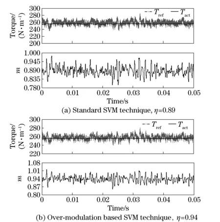
Inthispaper,allthesimulationresultsareatmaximumspeed2 800r/minandproperPIparametersarechosenforbestresultsinthesimulations.Inthesimulation,ηis set as large as possible while making ensure the control process can just work stably.ThemaximumηvalueunderstandardSVMtechniqueis0.89andtheresultisshowninFig.4a.InFig.4, TrefistherequiredtorqueofHEV, TactistheactualoutputtorqueoftheIPMSM.Thenincreaseηvalueuntilthecontrolgetunstableunderover-modulationmode.Fig.4bshowsthatwhenηvalueincreasesto0.94,theproposedstrategycanstillworkstably.Butwhentheηvalueincreasesto0.95,theproposedstrategymayalsogetoutofcontrol.Generally,over-modulationwillcausesomeproblemssuchasgreatcurrentandtorqueripple,sothecomparisonofsteadystatetorquerippleunderstandardSVMtechniqueandover-modulationbasedSVMtechniqueissimulatedandshowninFig.5.Itcanbeseenthatthetorquerippleunderstandardandover-modulationbasedSVMtechniqueisalmostthesame.Thatistheissueoftheproposedstrategy.Over-modulationisonlyusedinthetransitionprocesstoimprovedynamicperformanceandnotinsteadystate.Soitwillnotbringtorqueandcurrentrippleproblems.ThetorquerippleinFig.5comesmainlyfromthecurrentnoisesetinthesimulation,anditwillgetmuchlowerifthenoiseiscanceled.Thenitcanbeconcludedthattheproposedstrategywithover-modulationcanincreaseηvalueform0.89to0.94withthesamedynamictorqueresponse(20ms)andsteadystateperformance.Fasterorslowertorqueresponsecanbeachievedbydecreasingorincreasingtheηvalue.Buthigherηvaluemeanshigherefficiency,sotheηvalueshouldbesetasgreataspossiblewhentorqueresponsedemandissatisfied.

Fig.5 Comparison of steady state torque ripple
3 Experimental results
ThecontrolsystemshowninFig.1isimplementedwithaMC56F8346digitalsignalcontroller(DSC)fromFREESCALEandanIGBTinverterbasedonHybridPACK2fromInfineonTechnologiesAG.ThePWMfrequencyissetas5kHz,withhalf-cyclereloadcapabilityoftheDSC.ThefrequencyofcurrentPIcontrolleris10kHz.Inordertoimproveaccuracyofphasecurrent,thesamplingtimeofcurrentis50 μs, and an average filter is employed before used in current controllers.
The IGBT based inverter for the IPMSM is designed with 380 A as rated current and 570 A as maximum current. The system is powered by lithium batteries with rated voltage 288 V, and the working voltage range is from 252 V to 324 V.

Fig.6 IGBT drive voltage under different m at modulation frequency 280 Hz (according to 2 800 r/min)
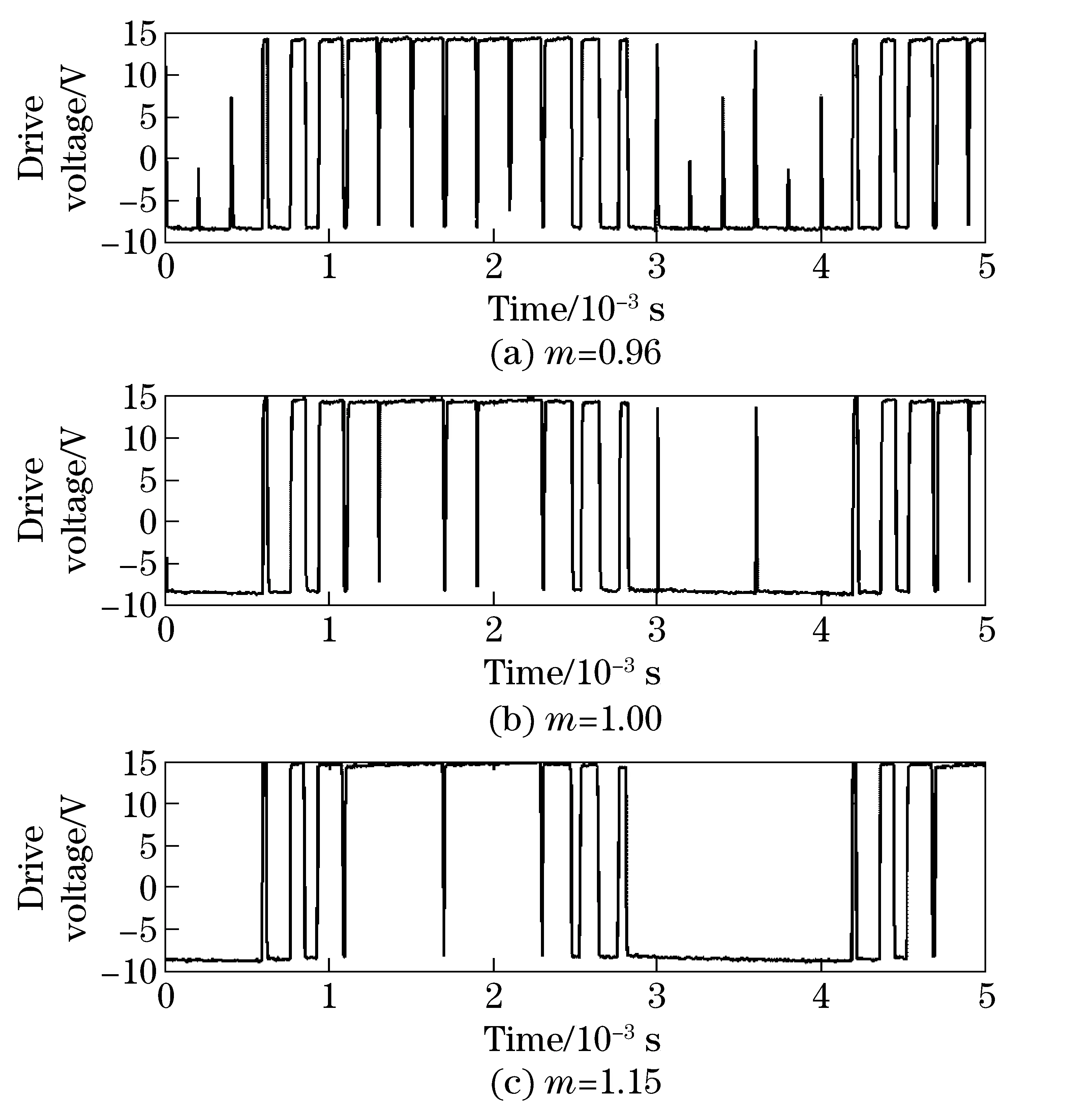
According to the characteristic of IGBT and driving ability of IGBT driver, the dead time is set as 4 μs. The driving voltage on IGBT is shown in Fig.6. It shows that whenmis 0.96, IGBT driver can just achieve complete modulation. Whenmis greater than 0.96, the inverter will work in over-modulation mode, which means the modulation rate has lost almost 4% because of dead time. In the experiment, the outputvdandvqfrom the current PI controllers is limited to [-0.96Vsmax, 0.96Vsmax] in standard SVM technique and [-1.15Vsmax, 1.15Vsmax] in over-modulation SVM technique, thenmis limited to [0, 0.96] and [0, 1.15].

Fig.7 Torque dynamic, current id and iq, and m under standard SVM technique, η=0.82
In the experiment, the clutch in HEV system is separated, and the IPMSM is working in speed mode. When the rated torque command is executed, the rotor speed will increase or decrease. Because the mechanical response speed is much slower than the electrical response speed, the speed change has little influence on the torque response results. The torque response with initial speed of 2 800 r/min is tested and shown in Fig.7 with the ηvaluesetas0.82instandardSVMtechniqueandFig.8withηvaluesetas0.89inover-modulationbasedSVMtechnique.Andtheηvaluesaresetwiththemaximumvalueaccordingtothetorqueresponsedemandforstableoperating.Intheresultfigures, TactisnotgetfromatorquetransducerbutcalculatedwithparametersofIPMSMandsamplingcurrent.Soithassomedeviationwithactualtorquevalue12andthatismainlycomingfromtheparametervaryofIPMSM,especiallyLdandLqvarywithstatorcurrent.Thereisalmost10%torqueerrorcomparedtoactualvalueintheexperiment.Theerrorcanbeeliminatedbyvariableparameterscontrol.Someexperimentswerecarriedouttoanalyzethisinfluenceonthestrategy,andtheresultsshowthatthereferencefluxweakeningvoltagewillchangewithvariableparameters,butthestrategyisstilleffective.Sointhispaper,inordertosimplifytheanalysis, LdandLqissetwithconstantvalue,thenthetorqueandcurrentvaluemayhassomeerrorwithsimulatedvalue.
Fig.7aandFig.8ashowsthetorqueresponsewithratedpositivetorquecommand,therotorspeedwillincreaseandthenIPMSMwillworkinlimitedpowerregion.Fig.7bandFig.8bshowthetorqueresponsewithratednegativetorquecommand.TherotorspeedwilldecreaseandthenIPMSMwillworkinconstantpowerregion.

Fig.8 Torque dynamic, current id and iq, and m under over-modulation based SVM technique, η=0.89
Itcanbeseenthattheηvalueintheexperimentdecreases0.07instandardSVMtechniqueand0.05inover-modulationbasedSVMtechniquecomparedtosimulatedresults.Fromtheaforementionedanalysisofdeadtime,itcanbeconcludedthattheηvaluereductionismainlycausedbydeadtime.
Whenthepositivetorquecommandis258N·mat2 800r/min,theaverageid, iqis-266A, 199.8Awithactualmaximumcurrent332.7A(Fig.7a)and-266A, 199.8Awithactualmaximumcurrent311.6A(Fig.8a).Thatistosaytheproposedstrategycanachievethesametorquewithaboutjust93.7%ofcurrentvalueintraditionalstrategy.Sothestrategycanachievehigherefficiencyandisabetterwaytoachievemaximumtorqueperampere(MTPA)controlinfluxweakeningregion.Whentheηvalueislargerthan0.82instandardSVMtechnique,thecontrolprocessmaygetunstable,thesameasinover-modulationbasedSVMtechniquewithηvaluesetas0.91.If10mstorqueresponsedemandisneeded,theηvaluemustbesetas0.82forrobustcontrolinover-modulationbasedtechnique,whichmeanstheproposedstrategyhasincreasedthetorqueresponseforalmost10mscomparedtostandardstrategywiththesamereferencefluxweakeningvoltage,whichmeanslargerfluxweakeningcurrentandlowerefficiency.Thatistosay,thedynamictorqueresponseperformancedemanddecidestheefficiencyinfluxweakeningregion.
4 Conclusions
Inthispaper,anover-modulationbasedvectorcontrolstrategyofIPMSMusedinHEVisproposed.Simulatingresultsshowthattheproposedstrategycanincreasethefluxweakeningreferencevoltageforalmost5%withouttakingintorqueandcurrentripple.Therelationshipbetweentorqueresponseperformanceandreferencefluxweakeningvoltagevalueisalsoanalyzed,withtheconclusionsthatfastertorqueresponseperformancedemandneedlowerreferencefluxweakeningvoltage,thenlargerfluxweakeningcurrentandlowerefficiency.Sointheapplication,thetorqueresponseperformanceshouldbesetasslowaspossiblejustmeetingthedemandtoimprovetheefficiencyofIPMSM.
Weexperimentallyverifiedtheproposedstrategy.Itcanachieveabout7%referencefluxweakeningvoltageincrementwiththesamedynamictorqueresponseperformance,thenachievesthesamesteadystatetorquewithlesscurrentinstandardSVMvectorcontrolstrategyinfluxweakeningregionanddoesn’tcauseotherproblems.
[1] Zhu Z Q, Howe D. Electrical machines and drives for electric, hybrid, and fuel cell vehicles[J]. Proceedings of the IEEE, 2007, 95(4): 746-765.
[2] Williamson S, Lukic M, Emadi A. Comprehensive drive train efficiency analysis of hybrid electric and fuel cell vehicles based on motor-controller efficiency modeling[J]. IEEE Transactions on Power Electronics, 2006, 21(3): 730-740.
[3] Davis R I, Lorenz R D. Engine torque ripple cancellation with an integrated starter alternator in a hybrid electric vehicle: implementation and control[J]. IEEE Transactions on Industry Applications, 2003, 39(6): 1765-1774.
[4] Kim J M, Sul S K. Speed control of interior permanent magnet synchronous motor drive for the flux weakening operation[J]. IEEE Transactions on Industry Applications, 1997, 33(1): 43-48.
[5] Rahman M F, Zhong L, Lee K W. A direct torque controlled interior permanent magnet synchronous motor drive incorporating field weakening[J]. IEEE Transactions on Industry Applications, 1998,34(6): 1246-1253.
[6] Tang L, Zhong L, Rahman M F, et al. A novel direct torque controlled interior permanent magnet synchronous machine drive with low ripple in flux and torque and fixed switching frequency[J]. IEEE Transactions on Power Electronics, 2004, 19(2): 346-354.
[7] Seok J K, Kim J S, Sul S K. Overmodulation strategy for high-performance torque control[J]. IEEE Transactions on Power Electronics, 1998, 13(4): 786-792.
[8] Kwon T S, Choi G Y, Kwak M S, et al. Novel flux-weakening control of an IPMSM for quasi-six-step operation[J]. IEEE Transactions on Industry Applications, 2008, 44(6): 1722-1731.
[9] Lee H D, Cho S K, Lee H S, et al. Advanced gear-shifting and clutching strategy for a parallel-hybrid vehicle[J]. IEEE Industry Applications Magazine, 2000, 6(6): 26-32.
[10] Holtz J, Lotzkat W, Khambadkone A M. On continuous control of PWM inverters in the overmodulation range including the six-step mode[J]. IEEE Transactions on Power Electronics, 1993, 8(4): 546-553.
(Edited by Cai Jianying)
10.15918/j.jbit1004-0579.201524.0311
U 266.2 Document code: A Article ID: 1004- 0579(2015)03- 0355- 06
Received 2014- 01- 08
E-mail: liuxiaohong@nuc.edu.cn
 Journal of Beijing Institute of Technology2015年3期
- Journal of Beijing Institute of Technology的其它文章
- High-rise building fire pre-warning model based on the support vector regression
- Dynamic modeling and simulation for the flexible spacecraft with dynamic stiffening
- Experimental study on the time-dependent dynamic mechanical behaviour of C60 concrete under high-temperatures
- Experimental study on compression stroke characteristics of free-piston engine generator
- Numerical simulation and optimization of the cylinder head water jacket based on the two-phase flow boiling heat transfer
- Multi-action-based approach for constructing knowledge map
