Numerical simulation and optimization of the cylinder head water jacket based on the two-phase flow boiling heat transfer
CHENG Ying(程颖), WANG Jia-wu(王家武)
(School of Mechanical Engineering, Beijing Institute of Technology, Beijing 100081, China)
Numerical simulation and optimization of the cylinder head water jacket based on the two-phase flow boiling heat transfer
CHENG Ying(程颖), WANG Jia-wu(王家武)
(School of Mechanical Engineering, Beijing Institute of Technology, Beijing 100081, China)
Boiling heat transfer and the controllability of the thermal load of the cylinder head were studied. The thermodynamic phase change characteristics of the cylinder head coolant were considered and the mass, momentum and energy transfers between two phases were calculated with the interface transfer sub-models by using the computational fluid dynamics software CFX. Results showed that compared with the single-phase flow without considering the boiling heat transfer, the sub-cooled boiling heat transfer of the cylinder head was greatly increased. According to the results of the numerical simulation, an optimized structure of the water jacket was proposed. Finally, temperature and velocity of coolant, diameter of flow passage and mean bubble diameter that influences sub-cooled boiling were studied using the orthogonal experiment method.
cylinder head; sub-cooling boiling; optimization; orthogonal design; simulation
The structure of the water jacket is complicated and the coolant flow inside the jacket cannot be easily observed and measured. The CFD is turned to be an effective mean for estimating and optimizing the water jacket system. But how to get accurate results is researchers’ goal. Nowadays, the numerical simulation of the engine cooling generally assumes that only single-phase forced convection heat transfer exists in the water jacket, ignoring the effect of boiling heat transfer. However, sub-cooled boiling heat transfer inevitably occurs in the heavy-duty diesel engine. Whether the sub-cooled boiling is taken into account exerts a great influence on the results of analyzing the heat transfer.
Based on the two-phase boiling model, we studied sub-cooled boiling heat transfer of the diesel cylinder head. The results showed that taking into account the effect of boiling phenomenon was necessity. According to the results of numerical simulation, an optimized structure of the water jacket was proposed. Finally, a simplified cylinder head was modeled according to the boiling zones of the original one, and the temperature and velocity of coolant, diameter of flow passage and mean bubble diameter that influences sub-cooled boiling were studied using the orthogonal experiment method.
1 Boiling heat transfer models
The boiling phenomenon occurred in the cylinder head is complex. Models for multidimensional theoretical description and analysis of sub-cooling boiling flow include Euler homogeneous flow boiling models, single-phase flow boiling models, and Euler two-fluid flow boiling models.
Euler homogeneous flow boiling models assumes that the vapor phase and the liquid phase have the common velocity field and the temperature field. The coolant is composed of vapor and liquidwith a fixed volume fraction[1]. Single-phase flow boiling models assumes that the scale of bubbles is very tiny and the bubbles intensively mixed with the liquid. The influences of the bubble movement to the liquid flow can be ignored[2]. The aforementioned two boiling models are relatively easy with mature solving technologies. They also have higher computing and convergence speed than the Euler two-fluid flow boiling models. But the assumption had a significant difference with the actual situation.
Euler two-fluid boiling models use two sets of conservation equations to govern the balance of mass, momentum and energy of each phase. By introducing the concept of the phase volume fraction, the macroscopic fields of one phase are not independent of the other phase and the interaction terms which couple the inter-phase transfer of mass, momentum and energy across the interfaces appear in governing equations. The first and most well-known model of this kind was formulated by Kurul and Podowski[3]. In this model, a number of the sub-models of the overall mechanistic model were taken from correlations. The sub-models include[4]: the model that describes the heat flux from the wall to the liquid, the model of wall nucleation site density, the correlation for bubble departure diameter, the correlation for bubble detachment frequency, the model that describes the bubble waiting time, the model that describes area influence factors, the model that describes convective heat transfer, the model of quenching heat transfer, the model of evaporation rate, etc. In this way, we used Euler two-fluid flow boiling models to precisely describe the complex heat transfer mechanisms. We applied Euler two-fluid flow boiling models to the cylinder head, the computational efficiency and convergence speed cannot be accepted because the structure of the water jacket is extraordinary complicated. However, the model is suitable for cylinder heads that use the drilling cooling whose flow passage cross section is circular.
2 Numerical method
The research was carried out in a diesel cylinder head, whose material was GJV300. We drilled circular flow passages in high temperature zones of cylinder head and cooled there. In this way, the regions of high temperature were cooled effectively[5]. Fig.1 shows the geometry model and finite model of the water jacket of the single cylinder.
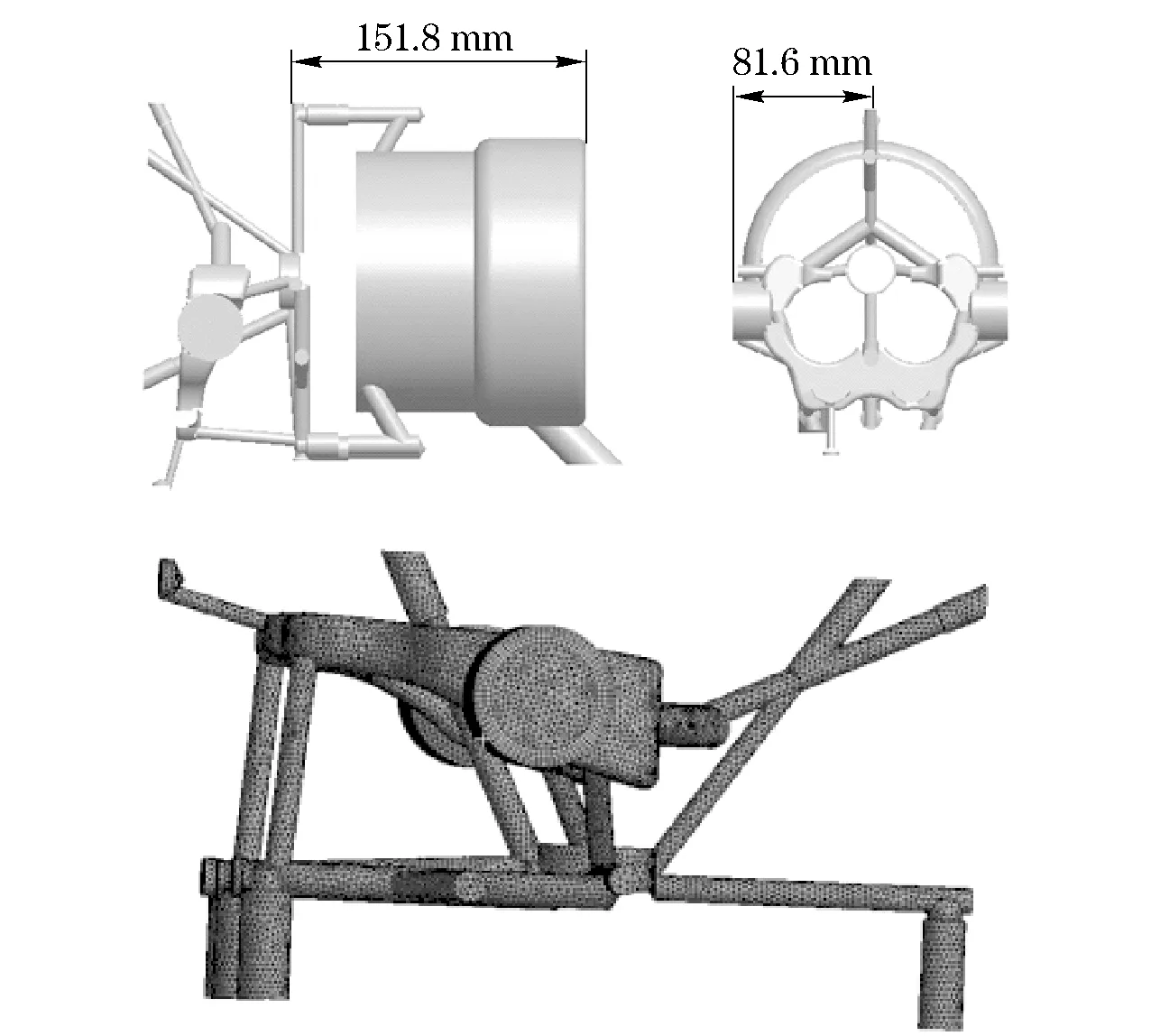
Fig.1 Geometry model and finite model of water-jacket
The composition of the coolant was distilled water. The calculations were performed with the finite volume and the steady state computational model was used. The liquid phase was dominant and described as continuous while the vapor bubbles were described as dispersed phase. Boundary conditions of a no slip for the liquid phase and a free slip for the vapor phase were used. The κ-εturbulencemodelwasemployedforthecontinuousphasewhilethedispersedvaporphaseremainedlaminar.TheSato’seddyviscositymodel[6-7]wasadoptedtocomputethebubbleinducedturbulenceviscosity.Theflowrate,thecoolanttemperatureintheinletofthewaterjacketandtheaverageoutletstaticpressurewereobtainedfromtheexperiments.
Constantthermalboundaryconditionwasadoptedontheheatedwall.Thethermalboundaryconditionsoftheflame-deckcanbedeterminedasfollows:Theinstantaneousgas-sidetemperatureTgandtheheattransfercoefficientofflame-deckhg,asshowninFig.2,wereobtainedbyGT-Powersoftware,andtheaveragevaluesweregainedas
(1)
(2)
wherehgmis the weighted average heat transfer coefficient of the gas in a cycle, τ0isthecrankangle,andTgmistheaveragetemperatureofthegasinacycle.
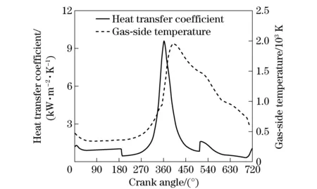
Fig.2 Instantaneous gas-side temperature and heat transfer coefficient of flame-deck
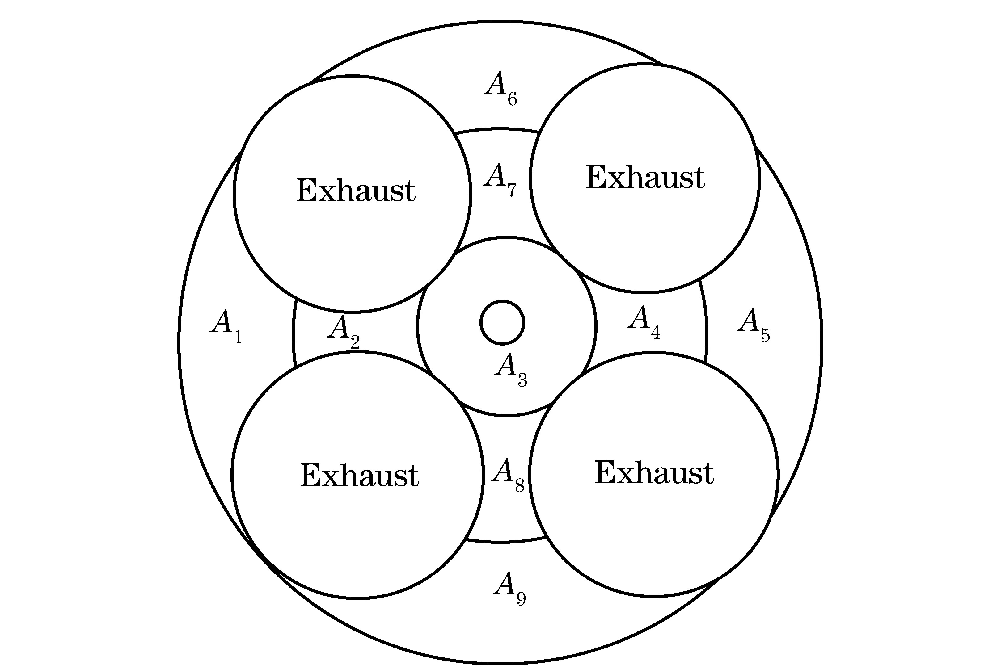
Fig.3 Zones in flame-deck
Thesurfaceoftheflame-deckwasdividedinto9zonesaccordingtothetemperaturedistributionasshowninFig.3.Theaveragegas-sidetemperaturewassetastheflamedeck’ssurfacetemperature.Theheattransfercoefficientofeachregionwasadjustedaccordingtothefollowingequation
(3)
untilthecalculatedvaluesandexperimentalvaluesatthemeasuringpointswerealmostequal.InEq.(3),Aiandhiare the areas and the heat transfer coefficient of each zone, respectively;Ais the total area of the flame-deck.
3 Results analysis
3.1 Forced convection results
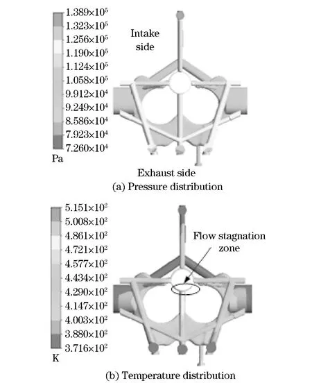
Fig.4 Pressure and temperature distribution of water jacket
The coolant of the cylinder head near the flame-deck was exposed to the heat flux from the gas side. The coolant temperature in thin-wall annular flow passage around the injector hole was very high due to the present of the flow stagnation zone and need to be further optimized[5]. Flow passages near the exhaust valve side were affected by the high temperature exhaust gas. Reasons mentioned above led to the high temperature of coolant in these areas. As shown in Fig.4, pressures of these regions were between 112 400 Pa-138 900 Pa, and the corresponding boiling point of water were 377.96 K-382.47 K. Obviously, there was boiling heat transfer occurred in some areas, and was quite necessary to consider sub-cooling boiling heat transfer in numerical simulation.
3.2 Comparison of the forced convection results and the sub-cooling boiling results
The water jacket was calculation with and without considering the sub-cooling boiling heat transfer, and the water flow field and the temperature of the cylinder head were compared accordingly. Fig.5 shows that the temperature distributions of the cylinder head were identical in both cases, namely, with and without considering the boiling heat transfer. The peak temperature occurs both in the bridge between the two exhaust valves. However, after considering boiling heat transfer, the peak temperatures of the cylinder head and the water jacket dropped 27.6 K and 48.6 K, respectively, as shown in Fig.5 and Fig.6.
As shown in Tab.1, the average heat flux of each zone in the flame-deck was improved greatly after considering boiling heat transfer among which the most obvious zone was in the area ofA4that rise by 10.24%. It can be concluded that the sub-cooling boiling enhanced the transfer of
heat flux and contributed to cooling of the high temperature region of cylinder head, producing a more uniform temperature field and reducing the temperature gradient of flame-deck. Therefore, the boiling heat transfer plays an important role in the simulation of the thermal load of the cylinder head.
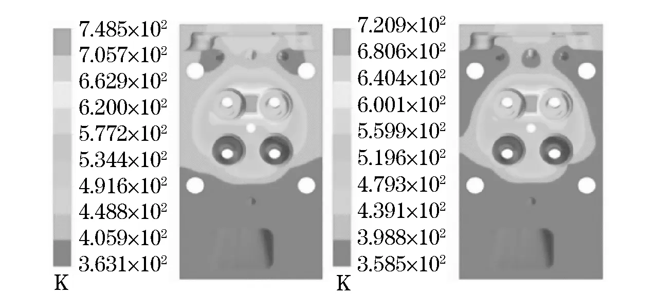
Fig.5 Temperature distribution of the cylinder head in different cases
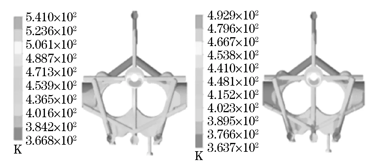
Fig.6 Temperature distribution of water jacket in different cases

Tab.1 Comparing heat flux in difference cases W·m-2
3.3 Analysis of two-phase flow in the water jacket
Fig.7 shows the distributions of the void fraction in the cross-sections of the water jacket. The locations of the cross sections are illustrated in Fig.1. There existed a large number of vapor bubbles in the flow passages of the exhaust valve side while there were hardly any in the intake valve side. The exhaust valve side withstood the heat flux transferred from the high temperature gas which caused boiling and producing more vapor bubbles.
In the passages of No.2, 3, and 4, as shown in Fig.7, which were closed to the flame-deck or the bridge between the two exhaust valves, presented a large number of vapor bubbles and the highest void fraction even reached 90% because the high temperature on the surfaces of these areas. As shown in Fig.8, the flow rates of these passages were relatively high (about 4 m/s) which could carry away bubbles in time and avoid blocking of coolant passages. The void fraction in the passage of No.1 was high as well, but the flow rate here was quite low which might block this passage and deteriorate cooling of cylinder head. It should be further optimized.
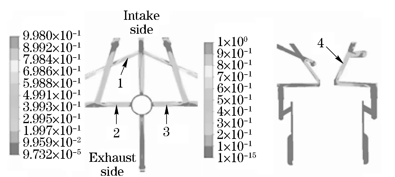
Fig.7 Void fraction distribution
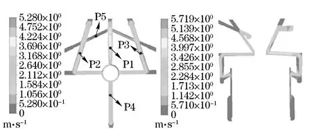
Fig.8 Velocity distribution
3.4 Optimization of the water jacket
Based on the analysis in previous section, measures to improve the flow condition of water jacket were taken as shown in Fig.9.
Measure 1: Reduced the flow passage’s diameter by 2 mm, which is the access to the upper of the cylinder head in the exhaust side directly.
So the greater flow of coolant through the passages that located in the bottom of the cylinder head firstly.
Measure 2: Changed the center circle of thin-walled annular flow passage into waterways, forcing the water flow through the injector bore around, eliminating the flow stagnation zone, as shown in Fig.9.

Fig.9 Modified model of water jacket
Measure 3: Added an outlet in the exhaust side to reduce the flow energy loss, and strengthen the exhaust side cooling.
As can be seen from Tab.2,Vp1is the velocity ofP1,VCis the velocity of center circle flow passage,Tfdis the temperature of flame-deck,Te-eis the temperature of the wall of exhaust passage,hwjis the heat transfer coefficent of the wall of water jacket.

Tab.2 Parameters comparison between the original and modified model
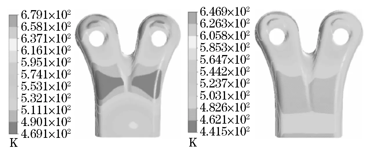
Fig.10 Temperature distribution of the exhaust passage
The locations of the points are illustrated in Fig.8, the optimized model had a significant improvement in the flow rate than the original model and the flow stagnation zone was eliminated. The temperature field of the exhaust passage became more uniform, as shown in Fig.10.
4 Factors influencing the boiling heat transfer
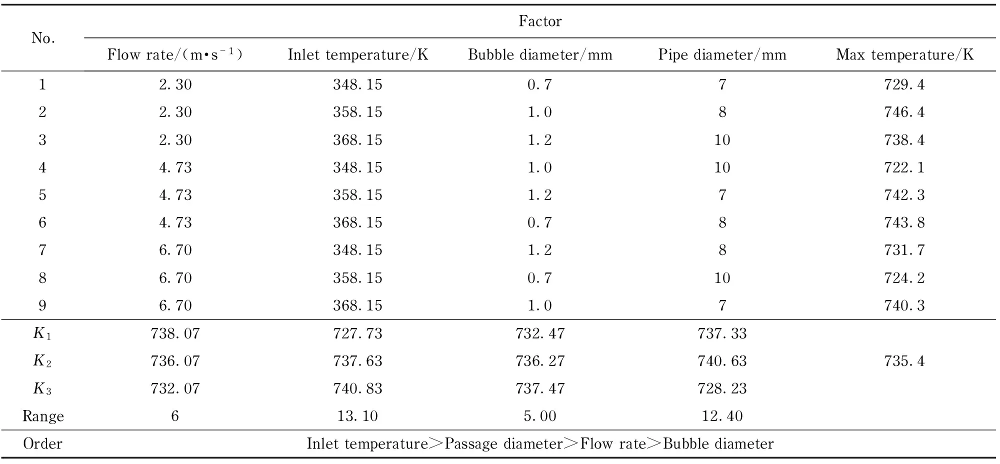
According to the actual work of the cylinder head, the flow rate, the temperature of coolant in the inlet of the water jacket, the cross section diameter of coolant passage and the bubble diameter are the main factors affecting the boiling heat transfer[8]. The orthogonal design method, which took the peak temperature in the cylinder head as the reference indicator, was adopted to study these factors. The L9(34) orthogonal table was chosen[9], and the results are demonstrated in Tab.3.
Tab.3 Orthogonal design table and the result
To reduce the calculation scale, based on the results of the previous analysis, the cylinder head and the cooling water jacketabout this type of diesel engine were simplified. The phenomenon of boiling heat transfer mainly occurs in the coolant passages close to flame-deck. Thus the simplified model maintained the flame-deck structure, and the coolant passage near the flame-deck remained unchanged, as shown in Fig.11.
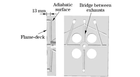
Fig.11 Simplified model
According to the values ofK1,K2andK3, each factor’s influences to the reference indicator can be obtained: as the flow rate in the inlet increases, the value of reference indicator trends to decrease. This may be attributed to the fact that higher velocities in the flow passage produce highly turbulent flow, thus, reduce the boundary layer thickness. Moreover, the bubbles can be carried into the bulk flow and condensed in time, hence improves the heat transfer coefficient of the wall. As the temperature of inlet flow goes up, the maximum temperature of cylinder head increases. For the fixed wall temperature, as the bulk temperature increases, the temperature difference between the wall and bulk reduces, hence heat flux carried by the coolant decreases. When boiling bubbles diameter increases, the void fraction in the flow passage increases, and the disturbance between the two phases is reduced. In this way, the cooling effect of the cylinder head is suppressed.
When the flow passage diameter increases, the wall heat transfer coefficient increases and enhances heat transfer; however, for the same inlet flow quantity, as the flow passage diameter increases, the flow rate in the passage will decrease, causing weakened cooling effect. According to the above two aspects, when the flow passage diameter increases to a certain size range, heat transfer of the cylinder head can be enhanced. But after the flow passage diameter increases beyond a certain level, the heat transfer coefficient drops because decreasing flow rate overwhelms the raises caused by the increasing diameter. Consequently, the heat flux decreases.
Range analysis results in Tab.3 show that the temperature of coolant and the cross section diameter of the coolant passage influence the peak temperature of the cylinder head in a larger degree than other factors.
5 Conclusion
In the heavy duty diesel engine, sub-cooling boiling heat transfer phenomena occurs inevitably. It exerts a greater impact on the simulation results and could not be ignored. According to the results of the numerical simulation, an optimized structure of the water jacket was proposed. The coolant flow rate, temperature, average bubble diameter and diameter of the coolant passage affects the boiling heat transfer. The temperature of coolant and the cross section diameter of the coolant passage are the main factors to the peak temperature of the cylinder head.
[1] Bo T. CFD homogeneous mixing flow modelling to simulate sub-cooled nucleate boiling flow, SAE paper 2004-0l-1512 [R]. Warrendale, PA, USA: Society of Automotive Engineering, 2004.
[2] Berezhkovskii L M, Zitserman V Y. Multidimesional theroy of homogeneous boiling of pure liquids[J]. Colloid and Interface Science, 1993,156(1):153-156.
[3] Kurul N, Podowski M Z. On the modeling of multidimensional effects in boiling channels[C]∥ANS Proc. 27th National Heat Transfer Conference, Minneapolis, MN, USA, 1991.
[4] ANSYS Inc. ANSYS CFX-Solver theory guide[M]. Canonsburg, PA, USA: ANSYS Inc, 2009.
[5] Yao Xiugong, Chen Ying, Gai Hongwu. Simulation and analysis of thermal load for diesel cylinder head[J]. Vehicle Engine, 2003(1):61-65. (in Chinese)
[6] Sato Y, Sadatomi M, Sekoguchi K. Momentum and heat transfer in two-phase bubble flow[J]. International Journal of Multiphase Flow, 1981, 7(2):167-177.
[7] Erfeng Chen, Yanzhong Li, Xianghua Cheng. CFD simulation of upward subcooled boiling flow of refrigerant-113 using the two-fluid model[J]. Applied Thermal Engineering, 2009, 29(11/12):2508-2517.
[8] Yang Shiming, Tao Wenquan. Heat transfer[M]. Beijing: Higher Education Press, 2006: 301-335. (in Chinese)
[9] Pan Lijun, Cheng Jingquan. Expermental design & date processing[M].Nanjing: Southeast University Press,2008:73-87.(in Chinese)
(Edited by Cai Jianying)
DOI: 10.15918/j.jbit1004-0579.201524.0307
TK 422 Document code: A Article ID: 1004- 0579(2015)03- 0328- 07
Received 2013- 12- 30
Supported by the National Key Basic Research Program of China (1030021210710)
E-mail: chengy@bit.edu.cn
 Journal of Beijing Institute of Technology2015年3期
- Journal of Beijing Institute of Technology的其它文章
- High-rise building fire pre-warning model based on the support vector regression
- Dynamic modeling and simulation for the flexible spacecraft with dynamic stiffening
- Experimental study on the time-dependent dynamic mechanical behaviour of C60 concrete under high-temperatures
- Experimental study on compression stroke characteristics of free-piston engine generator
- Multi-action-based approach for constructing knowledge map
- Slow driving control of tracked vehicles with automated mechanical transmission based on fuzzy logic
