Sealed model and computation of hazardous waste landfill high voltage DC leakage detection①
Yang Ping (杨 萍
(School of Information, Beijing Union University, Beijing 100101, P.R.China)
Sealed model and computation of hazardous waste landfill high voltage DC leakage detection①
Yang Ping (杨 萍②
(School of Information, Beijing Union University, Beijing 100101, P.R.China)
According to the structural characteristics of hazardous waste landfill and the leakage current model of high voltage DC Landfill leakage detection, a sealed model is established and analyzed in detail. The detection layer of the hazardous waste landfill is considered as a sealed space and it is assumed that the source current flows through the leak entirely. The leak is regarded as a positive current resource +I located at the current entrance or a negative resource -I located at the current exit, which depends on the placement of the current supply. The electrical potential of an arbitrary in detection layer satisfies Poisson equation. The boundary condition is regarded as a natural boundary condition for the high resistivity of high density polyethylene (HDPE) membrane. Based on which a numerical calculation method is developed. Satisfactory agreement between experimental data and simulated data validates the analysis. Parametric studies show that a larger horizontal distance between the power supply electrode and leak and a smaller distance between the detector electrodes and the detected liner are helpful to leak location. More parametric curves show that parameters leaks can be detected effectively with optimum selection of field survey.
hazardous waste landfill, high voltage DC method, sealed space model
0 Introduction
High voltage DC potential detection has been developed to detect and locate leaks in geomembrane liner used in waste landfill to prevent environment from leachates contamination[1-4]. To establish a basis for evaluating the technique, Parra developed a theoretical analysis method that characterized the three-dimensional response of single leaks[5,6]. Wait developed a simple model and regarded the leak current as a point current source[7,8]. Author’s preliminary work showed that the leak current could be regarded as a negative current resource at the entrance or a positive one of the same size at the exit[9]. Based on the fact that the single-liner landfills always had a large scale, a stratified medium model was established[10-12], in which the waste material, the liner, and the soil under the liner were simulated as infinite in the horizontal direction. The relationship between the fraction of leak current I0to total current Isand the surface area of landfill has also been analyzed. And the results show that the relative amount of source current flowing through the leak decreases as the size of the geomembrane liner increases. For a waste landfill having an area of 3600m2(rl=60m), 90 percent of the source current flows through the leak. Theoretically all the studies are about single-liner waste landfill. However hazardous waste landfills and storages usually use double geomembrane liners and the scale of which is only about several thousands of square meters. It is unreasonable to simulate the hazardous waste landfill as an infinite stratified model[13], and the influence caused by side boundary is not negligible especially when a leak is near the boundary. Experiments in Chinese Research Academy of Environmental Sciences also demonstrate a big error when the stratified medium model is used to detect leaks in small scale double-liner landfill of 2000m2in area.
According to the structural characteristics of hazardous waste landfills and the leakage current model of high voltage leakage detection, a sealed model is deeply discussed. In this paper, the detection layer is considered as a sealed space and it is assumed that the source current flows through the leak entirely. The leak is regarded as a positive current resource +I located at the current entrance or a negative resource -I located at the current exit, which depends on the placement of current supply. The electrical potential of an arbitrary in detection layer satisfies Poisson equation. The boundary condition is regarded as a natural boundary condition in view of the high resistivity of the HDPE membrane[9,14]. On the basis of above assumptions, hazardous waste landfill leakage detection’s sealed space model is established and analyzed in detail.
1 Principle
The electrical leak location method makes use of the high electrical resistivity of the geomembrane liner material. When no leak is presented, a voltage impressed across the liner produces a very low current flow. The low current density produces a relatively uniform potential distribution in the detection region. A leak in the geomember liner provides a conductive path for current flow, which produces an increase in the current density at the leak point. So the leak can be equaled to a current source. The localized current density causes an anomaly in the measured potential in the vicinity of the leak. Therefore, leaks can be located by measuring the potential distribution patterns in the material of the detection layer[15]. The basic principle is shown in Fig.1. For a double-lined hazardous waste landfill or storage, the detection layer can be regarded as a sealed space. Under this condition, the electrical potential distribution caused by a steady current is difficult to express analytically. So a new method is advanced to solve the problem of the potential distribution in the sealed detection region.

Fig.1 Principle of hazardous waste landfill high voltage DC leakage detection
2 Model and analysis
2.1 Sealed space model
The detection layer can be taken as a sealed space encapsulated by high resistivity material. The upper surface and lower surface are primary geomembrane and secondary geomembrane respectively. They are all composed of HDPE membrane with resistivity ρl=1014Ω·m[9]. The detection layer of depth h is full of clay soil with resistivity ρc=100Ω·m. A circular leak of radius a located at (x0, y0, z0) is used to represent the leakage in geomembrane liner, which provides a channel for current flow. If the current source outside the sealed space is positive, then the current flows from the leak to the current return electrode located at (xs, ys, zs). Since it provides a high current density which is equivalent to a current resource, the leak in the high resistivity material is regarded as a positive current resource I0located at the center of the leak. So the electrical potential φ of an arbitrary point in detection layer is the superposition of electrical potential caused by the leakage current I0and the return electrode current -Is. And the electrical potential φ satisfies Poisson equation ▽2φ=f[16-18].

f=ρcI0δ(x-x0)(y-y0)(z-z0)-ρcIsδ(x-xs)(y-ys)(z-zs), where ρcis the resistivity of the detection layer material, (x0, y0, z0) and (xs, ys, zs) are the coordinates of the leak and the current received electrode respectively. I0and Isare the leakage current and the return electrode current. δ(x) is the δ function .The model is shown in Fig.2.

Fig.2 Sealed space model of hazard waste landfill high voltage DC leakage detection
The interfaces continuity of potential and current density requires that[16,17]:

For a highly resistive liner, ρl>>ρc, which reduces the function to
where φlis the electrical potential distribution in the thin geomembrane liner. And n is outside normal direction. Considering the current density approximately equal to zero in n direction, it can be derived that Is=I0.
For a sealed region, it is difficult to give the analytical solution of the above Poisson equation. So a numerical calculation method is imported.
2.2 Mathematical analysis
2.2.1 Variational principle
The variational principle is known to us that,[18]a differential equation defined by
Lφ=f
(1)
If L is a selfadjoint operator, which means that

(2)
where φ and φ are the arbitrary functions that have the same boundary conditions, <> is an operation defined as
<φ,φ>=∫Ωφφ*dΩ
(3)
where Ω expresses the region in question, * represents the complex conjugate operation.
δF(φ)=0
(4)
(5)

(6)
Because φ, f are real functions, <φ, f>=

(7)
From the scalar Green theorem, it is deduced that[19]:

(8)

(9)
2.2.2 Regional division

2.2.3 Interpolation
After regional discrete, unknown function φ in every tetrahedral element need to be expressed. Hence the tetrahedral element as Fig.3 is taken into account. In every tetrahedral element e, the unknown function φ can be described as[20-22]
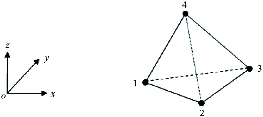
Fig.3 Linear tetrahedron cell
φe(x, y, z)=ae+bex+cey+dez
(10)

(10-1)
(10-2)
(10-3)
(10-4)
Based on the above equations, it can be deduced that:

(11-1)

(11-2)

(11-3)
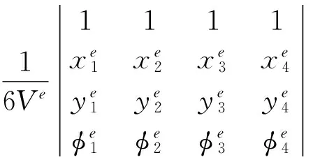
(11-4)
where
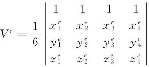
Taking the Coefficient ae、be、ce、deback to φe(x,y,z)=ae+bex+cey+dez, the following is got:
(12)
(13)
2.2.4 Calculation formula of Ritz method
After regional discretion and interpolation, Eq.(9) can be expressed as
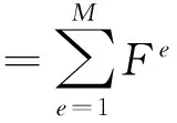
(14)
where M is the total amount of the tetrahedral element,

(15)


(16)
The matrix form is

(17)
where:
(18)
(19)
Based on the fundamental formulae[17,18]:
(20)
(21)
2.2.5 Combined into equations
Based on Eq.(17), combining with all units, and imposing the Stagnation point condition to F, the following equation is got:
(22)
The compact form is
[K]{φ}={b}
(23)
where
2.2.6 Solution of the equations
Generally, K in Eq.(22) is divided into an Upper triangular matrix U and a lower triangular matrix L. That is
K=LU
Firstly, the matrix equation is solved: Lφ=b
(24)
Then: Uφ=φ
(25)
Use the Crout decomposition method[19-21]
uii=1
i=1,2,3,…,n (26)
i≥j (27)
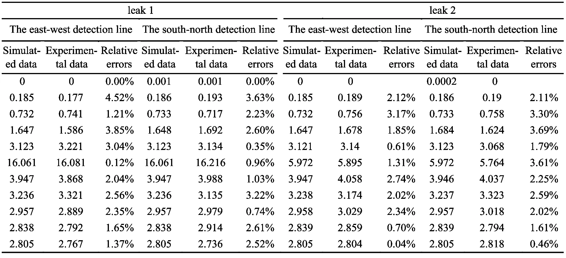
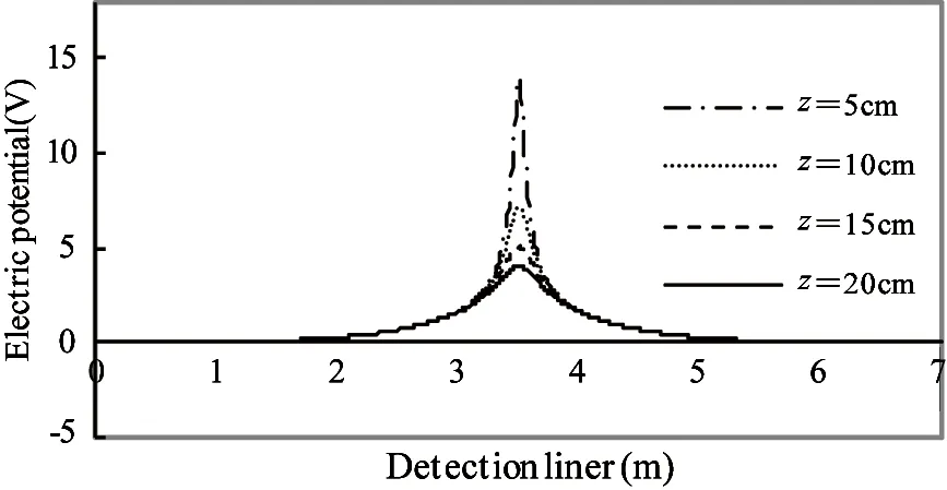
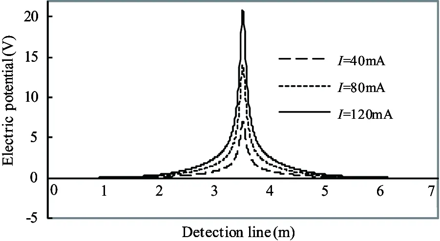
i Through step forward, φ[22]is obtained (29) i>1 (30) Then, through step backward, the value of φ at the endpoint of a tetrahedral element is got. φn=φn (31) i Finally, the value of φ at any point (x, y, z) can be obtained by element interpolating function. 3.1 Experiment verification To verify the validity of the model in locating leaks in geomembrane liner of hazard waste landfill, experiments are made at a double-lined simulated landfill (10m×10m×0.4m). As is shown in Fig.1, the landfill has two HDPE geomembrane liners with the thickness t=2mm. The primary liner is covered with water of 0.3m in depth. The detection layer of 0.4m depth is between the primary liner and the secondary liner. Fixed detection electrodes are buried in the detection layer during the construction of the simulated landfill, with 1m-distance from each other and 0.1m from the primary liner. One leak is on the primary liner, the other leak is on the secondary liner. Two leaks are on the center of the 11×11 measurement electrodes. To create an electrical flow through the leak, the positive electrode of DC current source is placed in the water used to simulate the hazardous waste when detecting primary liner or in soil when detecting secondary liner, the negative electrode (current return electrode) of DC current source is placed in the detection layer at the position (9.9, 0.1, 0.08) to form the current passage. The fixed electrode measurement is carried out by installing a potential reference electrode at the position (10, 5, 0.08), which is used to provide a common reference point for the potential measurements (the coordinate system in Fig.2 is referenced here). 121 data are collected over an area of 100m2. Table 1 shows the sealed model parameters for locating leaks. These parameters come from the test result of the facility. Table 1 Model parameters[23,24] Table 2 shows the experimental data collected from the detection electrodes laid on two crossed lines under or above the leaks and the corresponding simulated value based on sealed model. Leak 1 is located at the center of the primary liner. Leak 2 is located at the center of the secondary liner. The relative errors are also shown in Table 2. Data in Table 2 show that the relative errors between simulated data and experimental data are less than 5%. Considering the location error of detection electrodes during construction, the errors in measurement and the influence caused by noise and other factors, it can be concluded that the analysis method given above is valid. 3.2 Parameter study The parameter studies below are aimed at charactering the performance of the method for variations in the detection layer material electrical parameters, the contamination, the detection electrodes and current supply electrode position, and the detection layer depth. The result demonstrates the general applicability of the method and may be used to optimize the technique for specific landfill survey application. 3.2.1 Effect of detection layer resistivity The detection layer material’s resistivity ρcis controllable, which can be changed during the construction of a waste landfill. Fig.4 shows the anomaly responses for varying detection layer resistivity for detection electrodes survey data measured at a depth of d=0.05m below the primary liner. These results demonstrate that the strength of the anomaly response is increased and leak detectability is improved for high detection layer resistivity. Table 2 Comparison of experimental data and simulated data of two survey lines (V) Fig.4 Distribution of the electric potential besides the leak for different resistivity of the detecting liner 3.2.2 Effect of the inhomogeneity of detection layer medium Leak in the liner allows the leachates from the waste materials to detection layer, so the resistivity of contaminated region will decrease. ρc′ is used here to present the resistivity of contaminated region. Fig.5 shows the family of leak anomaly responses for different contaminated hemisphere r and ρc′=10Ω.m . The anomaly decays rapidly as the contaminated radius increases, so the leakage should always be conducted timely. 3.2.3 Effect of detection electrodes depth A family of leak anomaly responses for several detection electrodes depths below a single leak located in the primary liner is shown in Fig.6, which indicates the substantial improvement gained in detection sensitivity when the detection electrodes are closer to the detection liner. That is to say, the survey should always be conducted to the detection liner as close as possible. Fig.5 Distribution of the electric potential besides the leak for different radius of the pollution area Fig.6 Distribution of the electric potential besides the leak for different vertical distance from the leak 3.2.4 Effect of leak current Fig.7 shows the anomaly responses for different leak current. The results illustrate that the higher the leak current, the higher the detectability. Fig.7 Distribution of the electric potential besides the leak for different current of the leak 3.2.5 Effect of the offset distance from the leak to current resource electrode The offset distance of the leak to current resource electrode affects the anomaly response. To illustrate this characteristic, Fig.8 presents the distribution of the electric potential besides the leak for different horizontal distance horizontal distance (hd) from leak to source electrode. In Fig.9, the distribution for different vertical distance vertical distance (vd) from leak to source electrode is given. As expected, when the horizontal distance is far enough (>10m), the vertical distance from leak to source electrode has little influence on the leak anomaly responses. But when the source electrode is just below a leak, the range of the leak anomaly responses is very small. It is hard to detect the leak under this circumstance. Hence, in order to detect the entire region of a landfill, there are at least two power supply electrodes in the detection layer. Fig.8 Distribution of the electric potential besides the leak for different horizontal distance (hd) from leak to source electrode Fig.9 Distribution of the electric potential besides the leak for different vertical distance (vd) from leak to source electrode For a hazardous waste landfill, when a high DC voltage is imposed on the both sides of the gemembrance liner, the detection liner can be seen as a sealed space excited by leakage current and the return electrode current, The leakage current is a positive current resource +I located at the current entrance or a negative resource -I located at the current exit. The electrical potential of an arbitrary in detection layer satisfies the Poisson equation. The boundary conditions satisfy natural boundary condition. Parametric studies show that big magnitude of leak current, high resistivity of detection liner, large horizontal distance between the power supply electrode and leak and small distance between the detector electrodes and the detected liner are helpful to leak location, but the vertical distance from leak to source electrode has little influence on the leak anomaly responses when the horizontal distance is far enough (>10m). The numerical method is effective in solving the problem of potential distribution in even an irregular region. But there exists some shortage such as low computational efficiency. How to improve the computation efficiency will be the emphasis for further research. Reference [ 1] Darilek G T, Laine D L, Parra J O. The electrical leak location method for geomembrane liners- Development and application. In: Proceedings of the Industrial Fabrics Association International Geosynthetics, San Diego, USA, 1989. 21-23 [ 2] Darilek G T, Laine D L. Understanding electrical leak location systems of geomembrane liners and avoiding specifications pitfalls. In: Proceedings of the 10th National Conference, Superfund, Washington, D C, USA, 1989. 27-29 [ 3] Smith B, Darilek G, Laine D. Enhanced geomembrane CQA through proper application of geomembrane leak location surveys. In: Proceedings of the Geosynthetics 2007 Conference Proceedings, Washington D C, USA, 2007. 16-19 [ 4] Darilek G, Laine D. Experience with geosynthetic clay liners as a conductive layer in geomembrane leak location surveys. Geosynthetics, 2007,14 (6):30-33 [ 5] Parra J O. Electrial response of a leak in a geomembrane liner. Geophysics, 1988,53 (11):1445-1452 [ 6] Parra J O, Owen T E. Model studies of electrical leak detection in geomembrane lined impoundments. Geophysics, 1988,53(11):1453-1458 [ 7] Wait J R. Complex resistivity of the Earth. Progress in Electromagnetic Research, 1989,1(1):171-175 [ 8] Wait J R. Simple model for current leakage in insulating liner. IEEE transactions on geoscience and remote sensing, 1994,32(2): 472-474 [ 9] Yang P, Nai C X, Dong L. Leak current model in leakage detection of HDPE liner using high voltage DC method . Acta Scientiae Circumstantiae,2005,25(10):1261-1364(in Chinese) [10] Yang P, Dong L, Wang Q. Multimedia model of single-liner landfill high voltage DC leak detection. China Environmental Science,2008, 28(1):63-67 [11] Zhao X C, Yang P, Zhang Y D, et al.Finite element simulation of high voltage direct current electricity technology for double liner landfill leakage detection. China Environmental Science,2007,27(1):76-79 [12] Guan S P, Nai C X, Dong L, et al. A direct current resistance circuit model for landfill leak detection. Acta Scientiae Circumstantiae, 2010. 30(6):1188-1192 [13] Wang Z C, Chen Y Y. Hazardous waste landfill leakage detection based on transmission lines model. Advances in Information Sciences and Service Sciences, 2011.3(9):17-24 [14] Nai C X, Dong L, Wang Q, et al. The stratified medium model for leakage detection in double liner landfills. Research of Environmental Sciences, 2008, 21(6):30-34 [15] Yang P, Jiang Y X,Wang Y N, et al. Study on double-liner landfill leak location algorithm. Journal of Beijing Union University, 2013,27(1),81-85 [16] Guan S P, Wang Y L,Nai C X. Application of electrical leak detection method in double-lined landfills.China Environmental Science,2011,31(12):2013-2017 [17] Qiao S, Zhou M Y, Bai L. Theory of Exploration Electromagnetic Field. Beijing: China University Mining Technology Press, 1989. (In Chinese) [18] Yao D Z, Liang J B. Method of Mathematics and Physical. Wuhan: Wuhan University Press, 1997. (In Chinese) [19] Lang K M. Method of Mathematics and Physical. Beijing: High Education Press, 1997. (In Chinese) [20] Zong Z H, Gao M L, Xia Z H. Finite element model validation of the continuous rigid frame bridge based on structural health monitoring part I:FE model updating based on the response surface method.China Civil Engineering Jouranl,2011,2(44):90-98 [21] Merla A , Donato D , Fazio D . Differential thermal infrared imaging for environmental inspection. Journal of applied remote sensing, 2014, 8(11):117-123 [22] Abuel N , Hossam M. Bouazza A. Numerical characterization of advective gas flow through GM/GCL composite liners having a circular defect in the geomembrane. Journal of Geotechnical and Geoenvironmental Engineering, 2009, 135(11): 1661-1671 [23] Gao M L. Study on the Finite Element Model Validation of the Continuous Rigid Frame Bridge Based on Structural Health Monitoring:[Ph.D dissertation]. Fuzhou: Fuzhou University, 2008 [24] Chen Y Y, Nai C X, Dong L, et al.Landfill leakage detection based on boundary localization method.Research of Environmental Sciences,2012,25(3) : 346-351 Yang Ping, born in 1974. She received her Ph.D and M.S degrees from college of Mechatronic Engineering of China Mining & Technology University (Beijing) in 2006 and 2003 respectively. She also received her B.S degrees from XinYang Normal University in 1997. Her research interests include signal acquisition & processing and mathematical modeling. 10.3772/j.issn.1006-6748.2015.04.012 ①Supported by the National Basic Research Development Program of China (No. 2010CB428506), the National High Technology Research and Development Program (No.2007AA061303) and Beijing Higher Education Young Elite Teacher Project (YETP1756). ②To whom correspondence should be addressed. E-mail: xxtyangping@buu.edu.cn Received on Oct. 14, 2014, Tian Jinwen, Wang Yanni, Xue Lin
3 Experiment and computation





4 Conclusion
 High Technology Letters2015年4期
