
FEM simulation and experimental verification of roll forming and springback process under complex contact conditions①
2015-04-17 07:17:12YanYu
High Technology Letters 2015年4期
Yan Yu(阎 昱)
(School of Mechanical and Materials Engineering, North China University of Technology, Beijing 100144, P.R.China)
FEM simulation and experimental verification of roll forming and springback process under complex contact conditions①
Yan Yu(阎 昱)②
(School of Mechanical and Materials Engineering, North China University of Technology, Beijing 100144, P.R.China)
The application of advanced high strength steel (AHSS) has an important significance in the development of the lightweight of automobile, but the parts made of AHSS usually have defects, such as fracture and large amount of springback, etc. In this paper, a model of multi-pass roll forming and springback process of AHSS is established with finite element software ABAQUS. Then a roll forming experiment is performed, and simulation and experimental results have been compared and analyzed. The model is established under complex contact conditions, including self-contact condition. The results shows that during the process of sheet bending, large Mises stresses appear at bending corners. The smaller the bending radius is, the larger the Mises stress and strain are. Thickness of sheet metal changes differently if the bending radius is different. When the bending radius exceeds a certain limit, the change tendency of the sheet thickness turns from increase to decrease.
roll forming, FEM simulation, springback, experiment, complex contact condition
0 Introduction
The yield strength of advanced high strength steel (AHSS) is 500MPa to 1500MPa, in which AHSS has a very good energy absorption performance, it plays an important role in the improvement of lightweight and security of automobiles, and has been widely used in automotive industry. AHSS is good at lower yield ratio, better strain distribution capacity, and higher strain hardening characteristics than other kinds of steel. The mechanical properties of AHSS is more uniform, so the fluctuation of springback value is small. The collision characteristics of AHSS is better, fatigue life is higher, so thickness of the steel could be reduced by using AHSS[1].
Lots of parts used in cars can be manufactured through the process of roll forming, which is a kind of sheet metal forming process, and a combination of geometry, kinematics, dynamics, material science, and many other aspects, which makes roll forming a strong empirical technology[2]. At the present stage, the design of rolls depends on the experience of designers. Finite element analysis (FEA) uses numerical method to simulate the real physical system, which is of high accuracy and cost saving. Applied to the roll forming technology, FEA can help researchers replace experimental verification with numerical simulation. With the help of numerical simulation, it can be seen that some physical phenomena inside the material cannot be seen through experiment. Finite element analysis is an effective method[3].
Many researchers have done a lot of studies on the FEM simulation of roll forming. In foreign countries, Ref.[4] simulated the roll forming process based on the finite element method, and they found a method that possible minimized occurrence of the edge buckling during the forming process. Ref.[5] showed that the roll gap had the largest effect on both the longitudinal bow and springback. Ref.[6] indicated that the simulation model could well reflect the real forming process, which is of great help to understand flexible roll forming process. In China, Ref.[7] found a way to reduce the appearance of flange edge-wave. Ref.[8] established the first FEM model of the local heating roll forming. Ref.[2] showed that the finite element simulation agreeds well with the experiments. Ref.[9] showed that the extreme value of equivalent plastic strain mainly appeared in the corner of contact area between the metal strip and the rolls. The studies above mostly aimed at the analysis and solution of the defects in roll forming process, but they did not pay much attention to the forming part after the residual stress was completely released. In this work, a roll forming process model of dual phase steel DP980 is established, and it is the first to analyze springback of the formed parts, and study the defects after forming.
The springback analysis is performed with ABAQUS/Standard using the *IMPORT option. The results from the forming simulation in ABAQUS/Explicit are imported into ABAQUS/Standard, and a static analysis calculates the springback. During this step an artificial stress state that equilibrates the imported stress state is applied automatically by ABAQUS/Standard and gradually removed during the step. The displacement obtained at the end of the step is the springback[10].
In this work, the roll forming and springback models of DP980 are established in finite element software ABAQUS. The bending angle of the target part is large, the degree of deformation is great, so the self-contact and refined steps are adopted. Finally, the simulation results and the experimental results are compared and the mechanism of forming is analyzed theoretically.
1 FEM modelling
This set of rolls includes 13 passes, the assembly of roll forming process in ABAQUS is shown in Fig.1, and the cross-section profile of each pass is shown in Fig.2. The blank size is shown in Fig.3, and the cross-section profile of the target part is shown in Fig.4. Since the cross-section profile and the force of the sheet during forming keeps symmetrical, only half of the sheet is modeled. The material property of sheet is listed in Table 1. The roller stand distance of the assembly is 250mm, the sheet thickness is 1mm, and the roll gap is 1mm, the whole distance of the model is 3700mm. It can be seen from Fig.4 that the edge of the sheet bends, folds and contacts itself after forming, so self-contact is needed in the model. In order to facilitate the modification of parameters in the model, an analysis step is set between every two adjacent passes. A sole analysis step is set when self-contact occurs, a total of 13 analysis steps is established. As displacement boundary conditions are applied, the sheet moves along the roll forming line while the rollers are fixed. Three corners can be seen through the cross-section profile of the target part shown in Fig.4, all the fillet radius of which are small. In order to reflect the deformation of the fillet part accurately, the mesh here is refined. Shell element S4R with reduced integral unit is used to build the sheet model.
Methods used to improve the calculation precision and reduce the calculation costs in the model are listed as follows:
The contact relations between rollers and sheet in one analysis step are established only when the contact occurs in this step. If the contact does not occur or the sheet leaves the rollers of this pass, the contact relations are released, as shown in Table 2. The calculation time can be reduced by 60% by doing this. That is why the analysis steps are refined.

Fig.1 The assembly of roll forming in ABAQUS

Fig.2 The cross-section profiles of each pass

Density(g/cm3) ElasticModulus(MPa)Poisson’sRatio YieldStrength(MPa)TensileStrength(MPa)7.82100000.36121168

Fig.3 Dimensions of blank sheet (unit: mm)
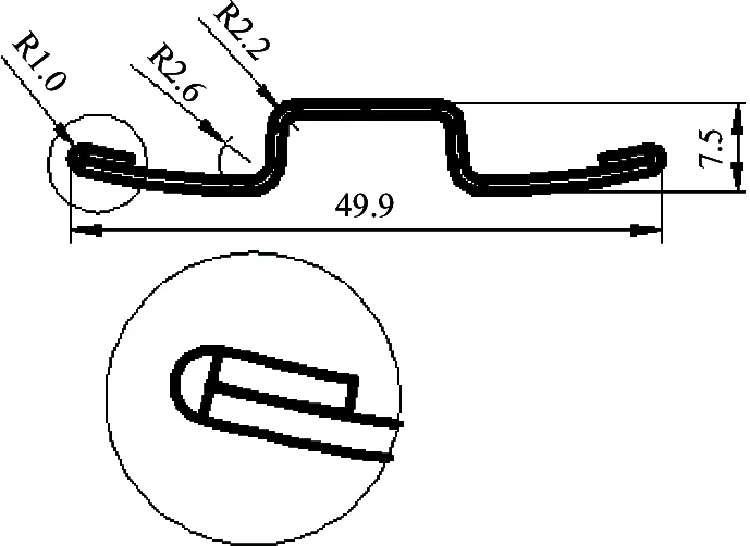
Fig.4 Objective cross-section profile (unit: mm)
The models of rollers are established with analytical rigid body, there is no need to mesh them, and the number of the element in the model is reduced.
Mesh in the forming area and fillet area is refined, and others that are not stress concentration areas can be meshed relatively rough. The mesh effect is shown in Fig.5, as the sheet is so long that only part of it is presented. The total number of the sheet elements is 12300.

Fig.5 Refined mesh of sheet

Pass1Pass2Pass3Pass4Pass5Pass6Pass7Pass8Pass9Pass10Pass11Pass12Pass13Step1√√ Step2√√√ Step3√√√√ Step4√√√√ Step5√√√√ Step6√√√√ Step7√√√√ Step8√√√√ Step9√√√√ Step10√√√√ Step11√√√√ Step12√√√√Step13√√√
The database file of the model above is imported into ABAQUS static implicit algorithm as predefined field of the resilience model to calculate the springback of the sheet after forming. The cross-section profile of the sheet after springback and the cross-section profile before are compared, as shown in Fig.6. It is shown that the springback mainly occurs in fillet area E, and the sheet bends downward, the springback angle is only 1.72°. It is because the bending radius is small, and it is 2.6mm. Part of the material here experiences plastic deformation. The bending radius of fillet area D is 1.0mm and the sheet here folds completely, therefore almost all the material here enters plastic deformation. The springback here is small, and the springback angle is 0.18°. The bending radius of the fillet area where F locates is 2.2mm, the shape here after springback coincides with the shape after springback as can be seen from the graph. Though the bending radius of area F is large, it has to undergo larger longitudinal tension than other fillet areas every time the sheet passes through the rollers of one pass, which is different from the pure bending stress state of area E. It is greatly constrained during the springback of the sheet, so the springback value is small. It can be concluded that the smaller the bending radius is, the smaller the springback amount.

Fig.6 Comparison of cross-section profiles before and after springback
2 Result and analysis
The Mises stress distribution and the final cross-section profile of the formed part are shown in Fig.7, and the final cross-section profile of the test specimen is shown in Fig.8. Measure the cross-section profile coordinates of the formed part, and then compare it with the graph made from the cross-section profile coordinates extracted from simulation, as shown in Fig.9. It can be seen that they coincide with each other in general. As the sheet model is built with shell element, the gap of contact area seems larger. In fact, the cross-section profile of the formed part is basically the same with the cross-section profile of the finite element simulation, which also verifies the feasibility of this finite element model.

Fig.7 The Mises stress contour of final cross-section profile in simulation (unit: MPa)

Fig.8 The final cross-section profile of the formed part

Fig.9 The comparison of two cross-section profiles
As shown in Fig.7, the Mises stress mainly concentrates on the fillet area where self-contact occurs, and the maximum Mises stress also occurs here. Pick a node from each of the three fillet areas from front sheet marked as A, B, C, as shown in Fig.10, and compare their stress values. The Mises stress of these 3 nodes during roll forming is shown in Fig.11. In order to have an easier observation, the comparison focuses on the self-contact analysis step. At the end of sheet forming, the Mises stress of nodes that locates in where the radius of fillet are 2.6mm and 2.2mm is small, which is less than 612MPa, the yield strength of high strength steel (HSS). And the Mises stress of node that locates in where the radius of fillet is 1.0mm is large, it is close to 1300MPa, which is larger than the yield strength of HSS, the sheet enters into plastic deformation state.
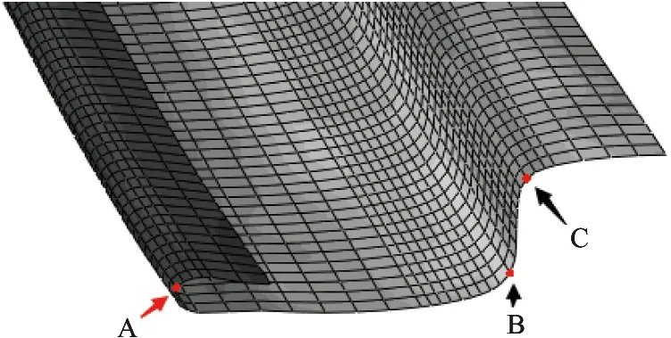
Fig.10 Position of the three nodes
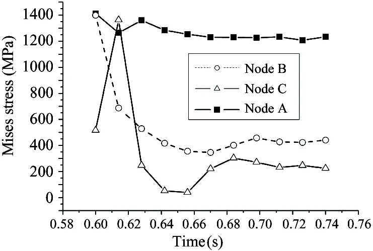
Fig.11 Mises stress curves of nodes changing with time
During the bending forming process of the sheet, the outside of the sheet bears tension, and the inside of the sheet bears compression, which will inevitably lead to the thickness difference in different areas of the sheet. The thickness contour of simulation is shown in Fig.12. Take the same three nodes as above, and compare the thickness values extracted from these nodes as shown in Fig.13. As can be seen from Fig.13, after 0.2s of the analysis time, the thickness of node B and node C tends to be stable, but thickness of node A remains fluctuating. That is because the corners around B and C are bended earlier, while the corner around A is bended later according to the forming process design. Thickness of node A becomes stable after the last pass, and the final thickness value of node A is 1.044mm. It means that in the bending forming process, the thickness of sheet varies differently with different bending radius. The thickness of sheet reduces in the areas where the fillet radius is 2.2mm and 2.6mm. The smaller the bending radius is, the larger the reduction of thickness is. The area where the fillet radius is 1.0mm is extruded by rollers greatly, which leads to the accumulation of material, so the thickness of this area increases slightly.
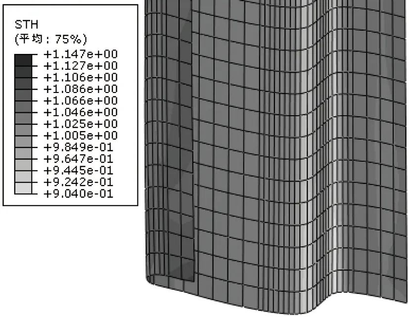
Fig.12 Thickness contour of sheet after forming (unit: mm)

Fig.13 Thickness curves of nodes changing with time
Equivalent plastic strain contour is shown in Fig.14. It can be seen that in the width direction of the sheet, the plastic strain of center area is small, large strain occurs in the fillet areas, and the largest plastic strain appears in the area of minimum fillet radius. In the length direction of the sheet, the equivalent plastic strain has zonal distribution obviously, and the plastic strain of bending areas is larger than the non-deformation area. Extract and compare the equivalent plastic strain values of node A, B, C, as shown in Fig.15. Rollers of first pass are plain rollers, so the equivalent plastic strain is 0 when the sheet passes through the first pass, which means the sheet does not deform at the first pass. Each time the sheet passes through a pass of rollers from the second pass, the sheet deforms and the equivalent plastic strain increases. After 0.2s of the analysis time, the strain value of center area tends to be stable because of the end of forming in these areas, while the bending forming at the edge part of the sheet does not complete, the strain value remains increasing. It can be concluded that the smaller the bending radius of sheet is, the larger the equivalent plastic strain is.

Fig.14 Equivalent plastic strain contour of sheet in simulation
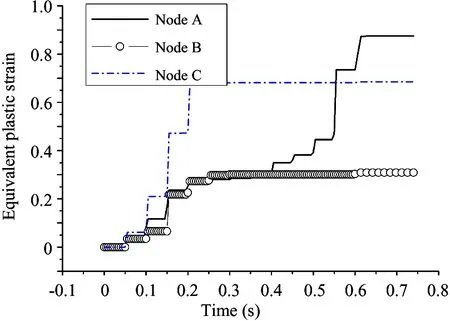
Fig.15 Equivalent plastic strain curves of nodes changing with time
The longitudinal strain curves of node A, B, and C are shown in Fig.16. It is similar to the curves in Fig.15. As can be seen in Fig.16, the strain of node A and C is tensile strain, and the strain of node B is compressive strain. The outside of the fillet bears tension, and the inside of the fillet bears pressure.
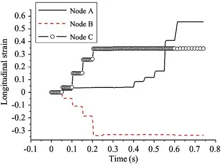
Fig.16 Longitudinal strain curves of nodes changing with time
3 Conclusions
(1) A 13-pass roll forming process of advanced high strength steel DP980 is modelled and simulated based on ABAQUS dynamic explicit algorithm. Then the result of simulation is imported into ABAQUS based on ABAQUS static implicit algorithm to calculate the springback after forming.
(2) General contact is used to establish interaction relationship, and the contact relations between rollers and sheet in one analysis step are established only when the contact occurs in this step so as to greatly improve the calculation efficiency. The sheet bends and folds, so self-contact is established in the model, and mesh of the fillet areas is refined.
(3) The corresponded roll forming experiment is performed, and the simulation results are compared with the experimental results. The results show that they are in good consistency, which is a verification of the reliability of the established roll forming model and the springback model.
(4) The springback of high strength steel after forming is calculated based on ABAQUS static implicit algorithm. The results show that the larger the fillet radius is, the larger the springback amount is.
(5) The equivalent stress and plastic strain of fillet areas during sheet forming are larger than other positions, and the variation of the sheet thickness is great. The smaller the bending radius is, the larger the equivalent plastic strain and the reduction of thickness are. The outside of the fillet bears tension, and the inside of the fillet bears compression.
[ 1] Ma M T, Shi M F. Advanced High Strength Steel and it’s Applications in Automobile Industry. Iron and Seel, 2004, 39 (7): 68-72 (In Chinese)
[ 2] Hu S D, Luo W, Chen N, et al. Simulation program for cold roll forming. Journal of Wuhan University of Science and Technology (Natural Science Edition), 2010, 33(5): 468-472 (In Chinese)
[ 3] Ni Z Y, Wang L F, Wu Z Q. FEM Simulation of Cold Roll Forming Process. Journal of Shandong Jiaotong University, 2007, 15 (3): 72-75 (In Chinese)
[ 4] Cavaguti M, Ferreira J V. Minimizing the edge buckling of the cold roll-forming process. IOP Conference Series: Materials Science and Engineering, 2010, 10(1):012139
[ 5] Wiebenga J H, Weiss M, Rolfe B, et al. Product defect compensation by robust optimization of a cold roll forming process. Journal of Material Processing Technology, 2013, 213(6): 978-986
[ 6] Yan Y, Wang H B, Li Q, et al. Simulation and experimental verification of flexible roll forming of steel sheets. The International Journal of Advanced Manufacturing Technology, 2014, 72:209-220
[ 7] Han F, Wang S P. Research of edge-wave mechanism in flexible roll-forming. Journal of Plasticity Engineering, 2013, 20 (5): 117-121 (In Chinese)
[ 8] Yang W Z, Yan Y, Cao K Y, et al. Analysis of local heating of high-strength steel roll forming. Journal of North China University of Technology, 2013, 25 (3): 76-81 (In Chinese)
[ 9] Liu X F, Lei J X, Ding H, et al. Numerical simulation of multi-pass roll forming process of anode plate. Die&Mould Industry, 2009, 35 (10): 6-11 (In Chinese)
[10] Abaqus 6.11 Online Documentation. http://abaqus.ethz.ch:2080/v6.11/: Dassault Systèmes, 2011
Yan Yu, born in 1983. She received her Ph.D degree from Beihang University in 2010. She also received her B.S. degree from Yanshan University in 2005. Her research interests include the finite element simulations, fracture and spring-back prediction for metal forming processes.
10.3772/j.issn.1006-6748.2015.04.009
①Supported by the National Natural Science Foundation of China (No. 51205004, 51475003), Beijing Natural Science Foundation (No. 3152010) and Beijing Education Committee Science and Technology Program (No. KM201510009004).
②To whom correspondence should be addressed. E-mail: anneyan@126.com Received on Aug. 26, 2014, Wu Qingyuan, Ai Zhengqing, Jia Fanghui
 High Technology Letters2015年4期
- High Technology Letters的其它文章
- Effect of laser heating on the microstructure and hardness of TRIP590 advanced high strength steel used for roll forming①
- Design of bilayer lengthened LDPC codes over expanded graph for relay channels①
- Secure planar convex hull protocol for large-scaled point sets in semi-honest model①
- Magnetometer calibration algorithm based on ellipsoid constraint①
- Motion mechanism analysis of two contacting rollers①
- Service optimization in programmable cloud network①