Analysis and active control of low frequency booming noise in car①
Cao Youqiang (曹友强
(China Automotive Engineering Research Institute Co. Ltd., Chongqing 401122, P.R.China)(State Key Laboratory of Vehicle NVH and Safety Technology, Chongqing 401120, P.R.China)
Analysis and active control of low frequency booming noise in car①
Cao Youqiang (曹友强②
(China Automotive Engineering Research Institute Co. Ltd., Chongqing 401122, P.R.China)(State Key Laboratory of Vehicle NVH and Safety Technology, Chongqing 401120, P.R.China)
For Lightweight body, sound radiation and sound insulation performance have negative effects on interior noise by the deterioration of local stiffness and modality. So the research on the active control of vibration and noise for car body panels is useful for engineering. Analysis and active control of booming noise in car is researched by using a new active damping vibration reduction technology named smart constrained layer damping (SCLD). According to the vibration characters of body roof, an optimal placement of actuators is distributed. Based on dSPACE hardware in loop environment, an adaptive active control system is designed. Selecting vibration signals of engine mounting point as the reference input of adaptive controller, an active control experiment of booming noise for mini-car is carried out. Experimental results show that , when the engine speed is at 3700RPM and 4250RPM, the interior booming noise decreases 4.2dB(A), and 3.5dB(A) separately. It proposes new methods and techniques for intelligent control of car body NVH in the future.
interior booming noise, smart constrained layer damping (SCLD), adaptive active control system, active control
0 Introduction
For Low noise and high quality cars, it does not only require taking low level of sound pressure in car, but also needs to realize comfortable acoustic environment. Light weight makes body panels to be thin which leads to the low stiffness, increased flexibility, and high modal density for low frequency. It will bring dynamic performance and NVH (noise, vibration, harshness) performance of body structure deteriorated inevitably. At the same time, light weight can produce low frequency booming noise which will affect the car’s acoustic environment seriously. Therefore, low frequency acoustic control of thin plate structure, and reducing the noise level in the carriage become the focus of global NVH researchers[1,2].
The interior booming noise is generated by larger response to the low frequency coupling mode between car body structure and acoustic cavity under external excitation. It is a kind of noise in narrow band with higher energy, and is one of the vehicle interior noise. In the automotive NVH design, the key point of solving the booming noise problem should be put at the elimination of excitation source. When a car is travelling in certain speed, or the engine is working at certain speed, the excitation force generated by the engine cannot be eliminated. This time, in order to avoid booming noise, we have to modify body structure (such as floor, ceiling, the front windshield, etc.). At present, with the help of modern CAE (computer aided engineering) technology, modifying the weak or sensitive parts to control the booming noise based on the calculation results and analysis on the body is the common method for most automobile manufacturing enterprises. But this idea is contrary to the lightweight goals, and the control measures are often contradictory with the body structure layout, so the control effect isn’t ideal. So for complex vibration system of lightweight body, it is necessary to explore new ways and means to further improve the body NVH performance, and develop innovative NVH solutions.
The smart constrained layer damping (SCLD) is composed of passive damping technology and active damping technology, a new kind of vibration damping technology[3,4]. It becomes a highlight of the structure vibration noise active control for nearly 10 years. And at present, although SCLD technology research has made a series of progress and exciting results at home and abroad, but the focus is mainly on numerical and laboratory research stage for the rod, beam, plate and shell structure[3-10]. However, the research that uses SCLD technology to the active control of complex vibration system is very little, especially for the car.
In this research, selecting vibration response of car body roof as the control target, combining with adaptive filtering active controller, the feasibility and potential of SCLD damping technology for car body vibration noise control is tried, and booming noise in car caused by body roof is obviously reduced.
1 SCLD structure characteristics
For SCLD smart structure, scholars have proposed many SCLD configurations[4],but the typical structure of SCLD is composed of three layers.From top to bottom, they are smart constrained layer, viscoelastic layer and the base structure respectively (as shown in Fig.1). It is similar to the passive constrained layer damping structure. The material of active constrained layer is completely consistent with the material of pure active control. Because the positive and inverse electrical characteristic of piezoelectric materials is obvious, and it’s successfully applied in the active control area, so far almost all SCLD structure use piezoelectric materials as actuators.
The basic work behaviour of smart constrained layer damping technology is: when the structure vibrates, the shear deformation of the damping layer happens, which can consume vibration energy, at the same time the piezoelectric constraining layer is stretched or compressed through active control loop, so that the shear deformation of the damping layer is strengthened. It can enhance the structural damping force, so as to improve the structural vibration energy dissipation capacity, and the structural sound radiation ability becomes weaker.
2 Analysis of interior booming noise
2.1 Selection of control object
In order to study the distribution characteristics of interior noise caused by engine excitation and determine the body panel part which causes interior noise obviously, the interior noise is tested.
At the stationary road state, the engine works from idle speed up to 5500RPM, and the right ear side of the driver and co-driver is measured by using the noise microphone. At the same time, in order to monitor the vibration characteristics of body structure vibration varied with engine speeds, vibration acceleration sensors are placed at the middle and rear of roof; as well as the front, middle and rear of floor. The interior noise test results are shown in Fig.2 and Fig.3.
Judging from Fig.2 and Fig.3, under the vehicle stationary road condition, the larger noise peaks of driver’s ear and co-driver’s ear appear at the near speed of 2500RPM, 3700RPM, and 4250RPM, especially the position of driver’s ear. And from the waterfall of interior noise response, it can be seen that, the interior noise energy mainly concentrats in the second order vibration frequency of the engine under the resonance speed. The corresponding excitation frequencies are 83.3Hz, 123.3Hz, and 143.8Hz respectively.
Through correlation analysis between body structure vibration and the car interior noise, combining with the comparison in each frequency band, the contribution of each part in different frequency bands for car interior noise can be identified.

Fig.2 The pressure response of driver’s and co-driver’s ear

Fig.3 The waterfall of acceleration noise response for car
Comparative analysis is found that: at 2500RPM, the middle and rear floor become the great contribution; at 3700RPM, rear floor, roof contribute significantly; at 4250RPM, roof contribute significantly. Thus, it can be seen that the roof is the main contribution component when the interior noise is higher than 100Hz.
However, from Fig.4 it can be seen that the structure vibration of roof is also the second order, and the frequencies are fit with the peak frequencies of interior booming noise.

Fig.4 The waterfall vibration response of roof
Obviously the engine excitation can be coupled with the low natural vibration frequency of roof when the engine is at speed of 3700RPM and 4250RPM, which can deteriorate the vehicle interior noise environment. Therefore, if the roof vibration at the resonance frequency is suppressed at the resonance speed, the interior noise response will be improved greatly.
2.2 Roof modal test
As a thin plate with large area for a body, the vibration radiation noise of roof is the main source of car interior noise. Due to the low stiffness, the roof is easy to produce low frequency vibration coupled with the 2nd order vibration of engine excitation. The analysis of roof vibration characteristic can find out the weak position or the coupling frequency band for engine excitation. So it can offer reference for the active control of roof vibration.
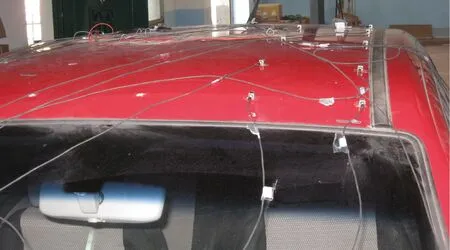
Fig.5 Modal test of roof
In the vehicle condition, the roof modal test (as shown in Fig.5) is done by using hammer with constraint condition. The excitation position is located at the connection of the B pillar and roof. The test results show that the constraint modal of the first six frequencies for the car are 118.14Hz, 129.53Hz, 138.30Hz, 141.93Hz, 154.30Hz and 162.71Hz respectively. Among them, vibration characteristic distribution for the first four frequencies are shown in Fig.6. From the modal testing result, it can be found that the low natural frequency of roof can be coupled with the engine excitation frequency occurred in the speed at 3500RPM~5000RPM. It will cause the roof resonance, which will form booming noise in car.

Fig.6 The first four test modes of roof
3 Active control of interior booming noise
3.1 Layout design of SCLD
On the analysis of the correlation characteristics between interior noise and vibration of the roof, active control tests for car interior noise are done at the engine speed of 3700RPM and 4250RPM.
Seven actuators (smart constrained layer damping structure, SCLD) are placed based on the 2nd and the 4th natural vibration shapes of roof, as shown in Fig.7. The size of piezoelectric actuator for SCLD is 105mm×56mm×0.7mm; damping material is Zn-1, which thickness is 1mm. Among them, taking into account the actual change characteristics of vibration phase, the phase distribution of SCLD active control is shown in Fig.8.
3.2 Active control test
Using piezoelectric smart structure to suppress interior noise is based on the active control of car body vibration response. The basic idea of active control is:
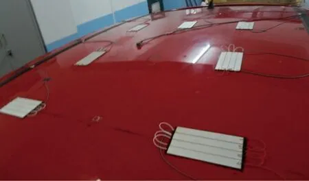
Fig.7 Layout of SCLD
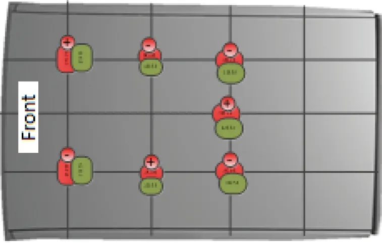
Fig.8 Phase distribution of SCLD(Upwards vibration is “+”)
the SCLD element is pasted on the surface of car roof; by acquiring the acoustic pressure response signal of driver’s ear caused by car body vibration, the signal is transmitted to the adaptive controller; after the corresponding control algorithm process, corresponding control signal is produced, and after the power of control signal is magnified, the SCLD actuator is driven which can make the car body produce strain to change the dynamic damping and inhibit the interior noise.
3.2.1 Experimental system
The experiment system of active vibration control for interior noise mainly includes: dSPACE hardware, B&K noise test system, pressure sensor, vibration acceleration sensor, constant current source device, charge amplifier, high quality piezoelectric drive power, low pass filter, computer and sensor wiring harness and so on, which are shown in Fig.9. The main equipment is shown in Table 1.

Fig.9 Active control experimental system based on dSPACE
3.2.2 Active control system and implementation
For the SCLD body, because of the model complexity and many uncertain nonlinear factors, it makes it difficult to set up dynamics model of controller. Obviously, the traditional control method often lacks consideration of the above factors, so it is not reasonable and it is difficult to meet the requirements of real-time control. Based on the above analysis, the adaptive filtering feedforward control method is applied to vibration adaptive control. It selects the outside disturbance signal as reference signal, and puts this signal to the controller, by using the adaptive algorithm to adjust the filter right coefficient ,and control the secondary vibration amplitude and phase, which can offset the vibration response caused by primary disturbances for controlled object. so the purpose of the structural active control is realized[11].

Table 1 Active control equipment and type
The adaptive filter feedforward control method is a new vibration control technology which can realize that the filter is in the best condition by adjusting the tap weight coefficient of filter with adaptive algorithm, so as to realize the aim to control structure vibration. To achieve the control process, it needs to set reference signal and error signal for the controller.
When the structure vibration response is controlled actively, the filtering process is realized by the FIR filter with fixed orders (Fig.10). Then the output response y(n) is
(1)
where the input signal

in which, x(n) is the filter input at k time. wi(n) is
the ith weight coefficient of the adaptive filter at n time, and w(0)=0. L is the filter order. Given the ideal reference response d(n), the error signal at n time step can be written as
e(n)=d(n)-y(n)=d(n)-wT(n)×X(n)
(2)

Fig.10 FIR adaptive filter structure

(3)
where γ is a small positive constant, and 0<γ<1.
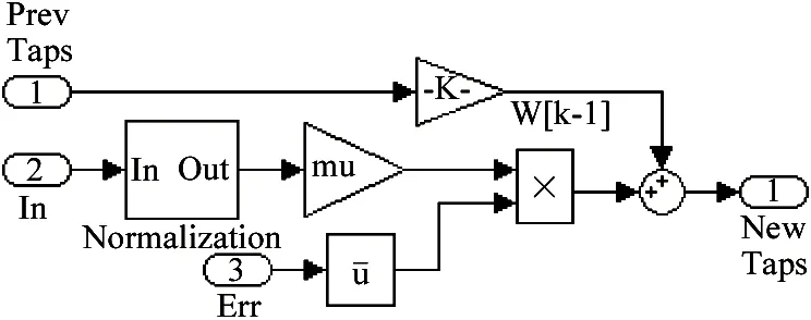
Fig.11 Diagram of normalized LMS algorithm
Based on MATLAB/Simulink, combining with dSPACE hardware in loop system, the adaptive vibration control system is designed in Simulink, as shown in Fig.12.

Fig.12 dSPACE/Simulink hardware in the loop control system
This research focuses on the interior vibration noise problems caused by engine excitation under stationary road state, which is mainly aimed at the interior active noise control caused by structure vibration, and the solution method belongs to the category of active structural acoustic control (ASAC). The active control test process is: firstly, adaptive active control system is designed and developed in Matlab/Simulink, and is downloaded to dSPACE hardware in the loop system. When the engine works properly, the car body panels are forced to vibrate caused by engine inspiration, so that large noise is caused in car. At this time, acoustic pressure sensor at driver’s ear can monitor the response of sound pressure quickly and this signal is transmitted to the adaptive control system in dSPACE; at the same time, the vibration signal measured by the acceleration sensor placed in the middle of engine mounting bracket, as the reference of the adaptive control system, accesses to control system after A/D conversion. When the two kinds of signals are received, active controller will quickly respond, and generate control signal to the piezoelectric drive power with analogy signal through the dSPACE output port. The amplified signal is directly imposed on the SCLD structure placed at car body roof, and makes SCLD structure generate expected action, so it can use the excellent damping performance of SCLD to restrain the vibration of body roof structure, so as to reduce the car interior acoustic field response. For observing the pressure change in car, the monitoring sensor is placed at the location of the rear middle part. Because the vibration structure frequency in the research is below 200Hz, in order to eliminate the high frequency signal (such as external environment noise, system current signal) influencing the control system stability, the low pass filter between zero to 200Hz is used in the internal control system.
3.2.3 Active control test and analysis
According to the designed test system, a hardware in the loop active control platform is set up for SCLD body structure , as shown in Fig.13. The monitoring sensor (see Fig.14) is placed at the rear middle part, which is measured by B&k test system. Before the test, the sound pressure and acceleration sensors are calibrated. And the test response value in dSPACE is revised based on sensor calibration value.
The adaptive active controller based on dSPACE system can add I/O interface in Simulink environment directly, and does not need to consider the programming of A/D, D/A interface. The model developed in Simulink is realized and downloaded to dSPACE hardware real-time processor by RTI. At the same time, the whole experimental process is controlled by control desk experiment software. This management platform can realize real-time online adjustment for active controller parameters and real-time visualization display for active control effect.
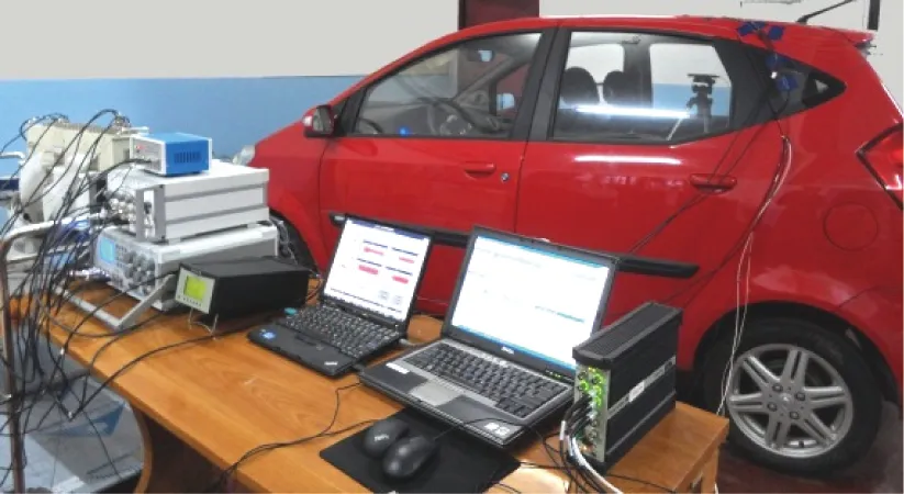
Fig.13 Experiment of active control for car interior noise

Fig.14 Microphone of driver’s ear and rear middle part
After active vibration control system of body roof is set up , as an exploratory research, the active control test of interior noise is researched when the engine speed is at 3700RPM and 4250RPM. In field test, the NLMS filter order of adaptive active controller is fixed with 16 and its convergence step is adjusted through online management platform. At the same time, considering the control circuit transfer effect and roof vibration characteristic, the feedback gain and active controller phase adjustment are introduced, which can be adjusted on line at control platform. In addition, due to microphone (FL) for driver’s ear is connected directly to the dSPACE system, and the microphone (MR) for rear middle part is connected directly to the B&K test system, so for the convenience of discussion, the FL microphone response results are given in time domain, while the MR microphone response results are given in frequency domain.
Controlling the engine speed nearly at 3700RPM and 4250RPM, and the active control test of interior vibration noise is done by SCLD active control technique. The time domain responses of driver’s ear microphone before and after control under two speeds are shown in Fig.15 and Fig.16; the frequency response curves of rear middle part microphone before and after control are shown in Fig.17 and Fig.18. The test results for under two working conditions are shown in Table 2.

Fig.15 Sound pressure response of driver’s ear in dSPACE when engine speed at 3700 RPM

Fig.16 Sound pressure response of driver’s ear dSPACE when engine speed at 4250 RPM

Fig.17 Frequency response of rear middle part microphone in B&K system when engine speed at 3700 RPM

Fig.18 Frequency response of rear middle part microphone in B&K system when engine speed at 4250 RPM

EnginespeedBeforecontrolSPLAftercontrolSPLNoisereductionBackgroundnoise3700RPM65.961.74.226.64250RPM67.463.93.526.6
From the above test results,it tells us that, using SCLD adaptive control system can effectively improve the interior acoustic noise environment when the engine speed is close to 3700RPM and 4200RPM. When the engine speed approaches 3700RPM, the noise response amplitude of driver’s ear decreases about 55% after control, which effect is obvious. But with the extension of time, after the interior noise response is weakened, the active excitation of active controller is to be outside noise source which makes the interior noise become bigger. While the engine speed approaches 4250RPM, noise response amplitude of driver’s ear decreases about 43% and the control effect is worse than that at 3700RPM, but the noise inhibition is still ideal. However the rear middle part response decreases 4.2dB(A) and 3.5dB(A) respectively when engine speed is near to 3700 RPM and 4250 RPM. When the engine speed is about 3700RPM, the main noise response amplitude of the rear middle part decreases from 42.8MPa to 27.4MPa, the sound pressure level decreases 35.98%; while the engine speed is about 4250RPM, it decreases from 51.5MPa to 33.5MPa, and the sound pressure level decreases 34.95%.
It is found that when car engine speed is higher, the car is more difficult to work at stable state. Of cause the frequency fluctuation will affect the whole control performance, and the stability for controller is more difficult to control. What’s more, as a result of taking internal noise signal as error sensor for adaptive filter controller, it is not avoidable that the external environment will affect signals, which wil also weaken control performance, especially when the engine speed is high. But on the whole, at specific speed conditions, for the thin plate parts such as car roof, placing SCLD structure based on the vibration shape can restrain interior booming noise level effectively, and obtain satisfactory control results.
4 Conclusion
For interior booming noise problems, according to the roof vibration shape, a distributed active SCLD controller is placed. An adaptive active control experiment system with NLMS algorithm is set up, and takes the driver’s ear noise as control objective; the experimental study on interior booming noise active control is carried out when engine speed is at 3700RPM and 4250RPM. It shows that the SCLD structure makes the interior booming noise achieve satisfactory noise reduction.
It further verifies that SCLD structure can effectively improve the low-frequency NVH performance of body panel structure. It provides a new solution for NVH control for lightweight thin-walled structure. Further researches will extend to the interior booming adaptive active control under multiple inputs and multiple outputs.
[ 1] Pang J, Chen G, He H. Automotive noise and vibration theory and application. Beijing: Beijing Institute of Technology Press, 2006
[ 2] Lin Y, Ma T F , Yao W M, et al. The summary of study on vehicle NVH performance. Automotive engineering, 2002, (3): 177-181
[ 3] Stanway R, Rongong J A, Sims N D. Active constrained layer damping a state of the art review. In: Proceedings of the Institution of Mechanical Engineers, Part I: Journal of Systems and Control Engineering, Professional Engineering Publishing, 2003(6),217: 437-456
[ 4] Trindade M A, Benjeddou A. Hybrid active-passive damping treatments using viscoelastic and piezoelectric materials: Review and Assessment. Journal of Vibration and Control, 2002, (8):699-745
[ 5] Baz A, Ro J. Vibration control of plates with active constrained layer damping. Smart Materials and Structures, 1996, (5):272-280
[ 6] Shen I Y. Hybrid damping through intelligent constrained layer treatments. Journal of Vibration and Acoustics, 1994,116(3):341-349
[ 7] Liu T X, Hua H X, Zhang Z Y. Robust control of plate vibration via active constrained layer damping. Thin-Walled Structures, 2004,4-2(3):427-448
[ 8] Azvine B, Tomlinson G R, Wynne R. Use of active constrained-layer damping for controlling resonant vibration. Smart Materials and Structures, 1995,4(1):1-6
[ 9] Liao W H, Wang K W. A new active constrained layer configuration with enhanced boundary actions. Smart Materials and Structures, 1996,(5):638-648
[10] Cao Y Q, Deng Z X, Xian M F, et al. active control of structural dynamic performance based on smart constrained damping technology. Journal of automobile engineering, 2011,1 (1): 18-26
[11] Haykin S S. Adaptive Filter Theory. Englewood Cliffs, NJ: Prentice Hall, 1991
[12] Liu J F. A novel adaptation scheme in the NLMS algorithm for echo cancellation. IEEE signal Processing Letters, 2001,8(1):20-22
5 Glossary
SCLD: Smart Constrained Layer Damping Structure
RPM: Revolutions Per minute
FIR: Finite Impulse Response
NLMS: Normalized Least Mean Square
ASAC: Active Structural Acoustic Control
RTI: Real-Time interface
Cao Youqiang, born in 1982. He received his Ph.D degrees in Vehicle Engineering of Chongqing University in 2011. He has nearly 8 years of automotive NVH research and engineering service experience, strong theoretical foundation of structure NVH , especially at the CAE analysis and control for car body NVH.
10.3772/j.issn.1006-6748.2015.04.006
①Supported by the State Key Development Program for Basic Research of China (No. 2010CB736104 ) and the National High Technology Research and Development Program of China (No. 2012AA111803).
②To whom correspondence should be addressed. E-mail: cyq_cqu@163.com Received on Oct. 12, 2014, Deng Zhaoxiang, Zhang Yu, Chen Dexin
 High Technology Letters2015年4期
- High Technology Letters的其它文章
- Magnetometer calibration algorithm based on ellipsoid constraint①
- Study and application of vibrating wire strain gauge in monitoring cable tension of FAST cable-net①
- Service optimization in programmable cloud network①
- Motion mechanism analysis of two contacting rollers①
- Design of bilayer lengthened LDPC codes over expanded graph for relay channels①
- Effect of laser heating on the microstructure and hardness of TRIP590 advanced high strength steel used for roll forming①
