
Development of two rescue robots for disaster relief operations in narrow debris①
2015-04-17 07:17ZangXizhe臧希喆
High Technology Letters 2015年4期
Zang Xizhe(臧希喆)
(State Key Laboratory of Robotics and System, Harbin Institute of Technology, Harbin 150080, P.R.China)
Development of two rescue robots for disaster relief operations in narrow debris①
Zang Xizhe(臧希喆)②
(State Key Laboratory of Robotics and System, Harbin Institute of Technology, Harbin 150080, P.R.China)
This paper proposes two novel rescue robots, including a cutter robot and a jack robot, which are aimed to contribute to rescue activities such as to cut through obstacles and to jack up debris in dangerous sites and narrow spaces, where a rescue team can not work or approach. Firstly, a multi-linked tracked rescue robot platform composed of connected crawler vehicles is developed, which has high mobility on irregular terrain and ability to move into narrow collapsed structures. Then, the cutter robot and jack robot are designed on the basis of rescue robot platform equipped with a cutter or a jack mechanism and corresponding manipulators in the front segment. The cutter refitted by an angle grinder is able to cut through 10 mm diameter steel bars. The electric jack mechanism designed based on multiple layers screw sleeves structure can lift up 300 kg load from 70 mm to 400 mm. Experimental results validate the capability of the two rescue robots.
rescue robot, connected crawler vehicles, cutter robot, jack robot
0 Introduction
Natural disasters such as earthquakes and tsunamis occur occasionally, having caused heavy losses to lives and properties of people in disaster-hit areas. It is proved in practice that victims are much more likely to survive during the window period of 72 hours after the earthquake for relief operations; after 72 hours, the chances of survivals are getting smaller owing to injuries and lack of food and water. Quick and efficient rescue operations play a significant role after such disasters occur. Therefore, a variety of rescue robots which are used to increase the efficiency and security of rescue operations have been developed.
According to the tasks to be completed, rescue robots can be divided into two categories. The first category of rescue robots, mostly equipped with gas detectors, radiation sensors and infrared cameras, aims to search victims and collect information in unknown dangerous environment, such as Packbot developed by iRobot and Souryu developed by Tokyo Institute of Technology[1-3]. In addition, some rescue robots including HELIOS VIII which is developed by Tokyo Institute of Technology are also mounted with a manipulator to accomplish some simple operations, for example, opening doors and grasping objects[4]. A lot of such robots have been developed. The second category of rescue robots which are not so many, aims to realize operations that need big power, for instance, cutting through obstacles, jacking up heavy debris and carrying victims. Tsukagoshi, et al. in Tokyo Institute of Technology proposed a series of jack robots named Bari-bari[5-7]. Tanaka, et al. in Okayama University designed a jack robot and a cutter robot in 2005[8-10]. These robots, driven by hydraulic actuators, are suitable for heavy-duty rescue operations. However, operators are required to stand by closely owing to limitation of the hydraulic tube.
According to the above situation, two novel rescue robots are proposed—a cutter robot and a jack robot. As the first step, a multi-linked tracked rescue robot platform is designed, which is with high adaptability and mobility on the irregular ground of disaster sites, and can be remotely controlled via wireless communication. As the second step, a cutter, a jack mechanism and corresponding manipulators are designed which can be equipped in the rescue robot platform to accomplish rescue operations of cutting through obstacles and jacking up debris.
This paper is organized as follows. Section 1 introduces design of the rescue robot platform. Section 2 and Section 3 introduce design of the cutter robot and the jack robot respectively. Experiments on the two rescue robots are presented in Section 4. And our concluding remarks are contained in Section 5.
1 Design of the rescue robot platform
1.1 Rescue robot platform
The rescue robot platform is aimed to carry rescue tools into disaster sites to accomplish rescue tasks such as searching victims, cutting through obstacles and jacking up debris. So it’s required to be slim enough to go through cracks and crevices with high mobility on rough terrain.
To satisfy the above requirements, a multi-linked tracked rescue robot platform is designed, which is constructed by two crawler vehicles - front and rear segments connected by active joint mechanism, as shown in Fig.1. The long and thin structure enables the rescue robot to enter into narrow debris. The front segment is able to pitch, yaw and roll relative to the rear one, ensuring the rescue robot good adaptability to complex terrain when traveling on irregular surfaces. Batteries, motion controller, joint driving motors and wireless communication module are all equipped in the rear segment to leave enough space for rescue tools in the front segment.
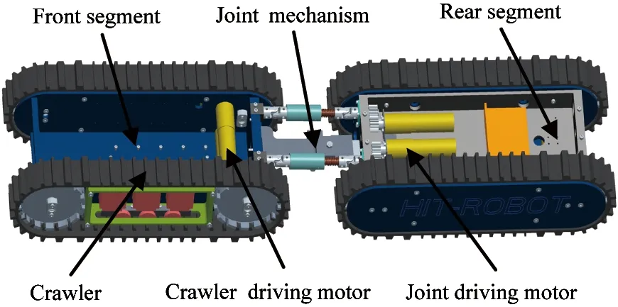
Fig.1 Structure of the two-linked tracked rescue robot platform
Designed on the basis of modular design method, configuration of the rescue robot platform can be easily changed by adding more segments to the end in accordance with practical demand, illustrated in Fig.2. With respect to three-linked tracked rescue robot platform, the front and rear segments are able to adjust posture relative to the center segment independently, ensuring its better mobility than two-linked tracked rescue robot platform. In addition, different kinds of rescue tools can be equipped in the front and rear segments to accomplish more rescue operations. However, three-linked tracked rescue robot platform has bigger size and heavier weight compared with two-linked tracked rescue robot platform.

Fig.2 Three-linked tracked rescue robot platform
1.2 Joint mechanism
The front segment is connected to the rear one by a special three dimensional joint mechanism which includes two layers, as shown in Fig.3. The upper layer consists of two active driving limbs. Each limb consists of a driving motor located in rear segment and a ball screw with universal joints on both ends. The lower layer consists of junction plates of 3-DOF -pitch, yaw and roll. The DOF of roll is controlled by the brake.

Fig.3 Joint mechanism
When the brake is applied, posture can be changed around the yaw and pitch axes by two screws driven by motors located in the rear body segment. When the brake is released, the front segment is able to roll. Such design allows the robot to adjust its shape corresponding to irregular surfaces, so that the driving force can be transmitted to the ground more effectively. Workspaces of the robot’s pitch and yaw are [-40°, +33°] and [-29°, +29°].
1.3 Kinematics analysis of the robot’s yawing
When ball screws of joint mechanism are driven to rotate towards different directions, one of the two ball screws lengthens and the other shortens, causing the front segment to yaw relative to the rear one. Kinematics analysis aims to get the relationship between the distances of ball screws. Fig.4 shows the schematic diagram of the robot’s yawing.

Fig.4 Schematic diagram of the robot’s yawing
Point A, B, C and D refer to the centers of universal joints and point E refers to the yawing center. Assuming that parameter β stands for the yawing angle at some point, the distances of ball screws indicated by P1and P2can be presented as,
(1)

(2)
In Eqs(1) and (2), values of m, n and α are determined by the structure of rescue robot. With the help of Matlab, the changing curve of P2with P1is plotted, shown in Fig.5. Within this figure, it’s obvious that the curve is approximately a straight line. In other words, the relationship between P1and P2can be treated as linear. When designing the control system, velocities of the two driving motors are set to the same value to simplify the control program.

Fig.5 Curve of P2 changing with P1
1.4 Kinematics analysis of the robot’s pitching
The front segment pitches when the two ball screws are driven to rotate towards the same direction at the same speed. A large range of pitching motion allows the robot to climb high vertical barriers more easily. However, owing to ball screws’ limited length, enlarging limit value of elevation angle is inevitably in accompany with reducing limit value of depression angle. Given that, an effective method is to determine the reasonable structure parameters by kinematics analysis of the robot’s pitching in order to achieve the optimal combination of elevation angle and depression angle.
Fig.6 shows the schematic diagram of the robot’s pitching. In this image, the values of L2and L3are already known, and X which refers to the distance between hinge joints in vertical direction is undetermined. At any time of the pitching procedure, length of ball screws denoted by L1has a certain value, and the value of pitching angle can be written as
(3)

Fig.6 Schematic diagram of the robot’s pitching
Assume that the initial value of λ before the robot pitching is λini. Then the elevation angle φ and depression angle ψ can be got as follows
φ=λmax-λini
(4)
ψ=λini-λmin
(5)
Change curves of elevation angle and depression angle with value of X are plotted in Matlab, shown in Fig.7. Value of X is determined following the principle of achieving both satisfying elevation angle and depression angle on the basis of the analysis result. In this design, the value of X is 31mm and elevation angle and depression angle are 33° and 40°. Once X is determined, the range of pitching angle can be obtained. Fig.8 presents the changing curve of the robot’s pitching angle with the distance of ball screws.
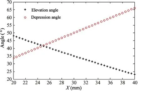
Fig.7 Curves of elevation angle and depression angle changing with X

Fig.8 Curve of pitching angle changing with L1
2 Design of the cutter robot
2.1 Cutter robot
The cutter robot is designed by equipping with a 3-DOF manipulator and a cutter in the front segment of the rescue robot platform, as shown in Fig.9. Its working process is depicted as follows. First of all, the cutter robot moves to the obstacles which need to be cut through. After that, the cutter stretches out from the front segment of the robot, adjusts to an appropriate pose for cutting operation and starts working. When the obstacles are cut through, the cutter moves back to the inside of robot and continues to the next task. Fig.10 shows working image of the cutter robot.

Fig.9 Overview of the cutter robot

Fig.10 Working image of the cutter robot
2.2 Manipulator and cutter
The manipulator of the cutter robot has three DOF: one translational DOF and two rotational DOF, as shown in Fig.11. The rack is fixed on the body frame of the cutter robot. When the motor rotates, the manipulator moves along the rack, extending outward from the front segment.

Fig.11 Manipulator of the cutter robot
By rotating around joint 1 and joint 2, the cutter mounted at the end of joint 2 is able to adjust its position and orientation. The cutter, illustrated below in Fig.12, is refitted by an angle grinder and possesses the ability of cutting through 10 mm diameter steel bars.

Fig.12 The cutter
2.3 Control system
The control system hardware architecture of the cutter robot consists of layers-control terminal, robot system and execution unit, as shown in Fig.13. The control terminal includes microcomputer, touch-screen monitor, wireless module and joystick. The robot system includes a motion controller, a wireless module and a camera. And the execution unit is composed of DC motors, drivers and encoders. The microcomputer on which the control system software runs communicates with the motion controller through the Modbus protocol via wireless modules, sends commands to motion controller, and accepts information of the cutter robot returned by the motion controller. Each execution unit is connected to the motion controller via CAN bus, ensuring the control system a high expansibility.
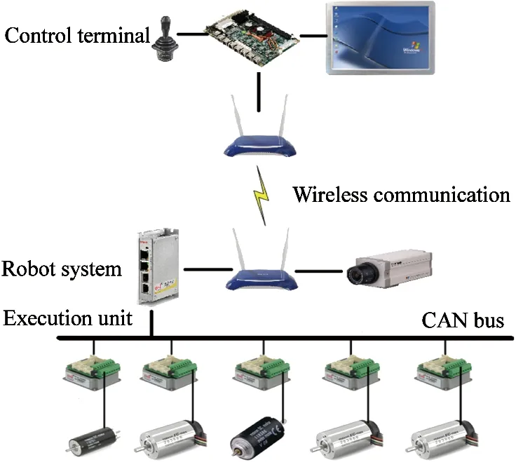
Fig.13 Hardware architecture of control system
The control system software of the cutter robot is shown in Fig.14. Watching the cutter robot directly or through the view from the camera displayed on the touch-screen monitor in real time, operator can realize control of the robot remotely by the joystick or by clicking on the buttons of the software. The motors are powered by two lithium batteries, each of which has a capacity of 10Ah, enabling the cutter robot to keep working about one hour. The wireless communication module can work steadily at distances of up to about 10 meters.
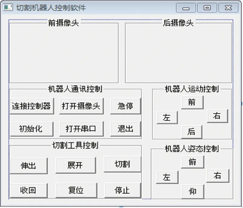
Fig.14 Control system software of the cutter robot
3 Design of the jack robot
3.1 Jack robot
Analogously, the jack robot is designed by equipping with a manipulator and a jack mechanism in the front segment of the rescue robot platform, as shown in Fig.15. Its working process is similar to the cutter robot. When reaching the destination place, the manipulator takes the jack mechanism out of the front segment and puts it at a specified point for jack-up operation. Then the jack mechanism lifts up the debris to make and keep enough space for rescue parties and other rescue tools. Fig.16 shows working image of the jack robot.

Fig.15 Overview of the jack robot
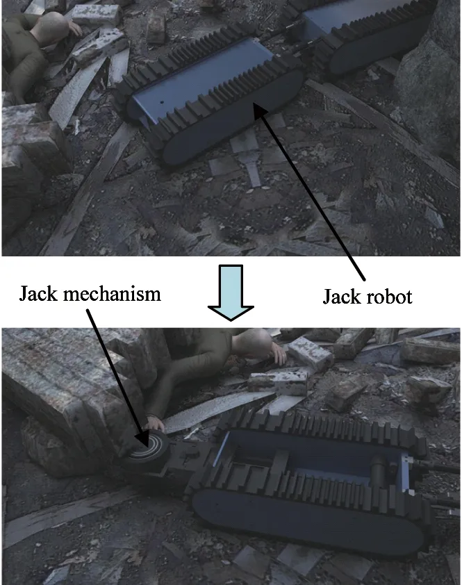
Fig.16 Working image of the jack robot
The control system of the jack robot is much the same as the cutter robot and needs not to be repeated in this paper.
3.2 Manipulator and jack mechanism
Fig.17 presents the structure of the jack robot’s manipulator. The gear meshes with a rack which is fixed on the body frame of jack robot. There is a gripper at the front of the manipulator. The jack mechanism is clamped by the gripper in the front segment. When the manipulator reachs out from the front segment along the rack driven by motor, the gripper spreads to the sides and then the jack mechanism is separated from the gripper.

Fig.17 Manipulator of the jack robot
The electric jack mechanism shown in Fig.18 adopts the structure of multiple layers screw sleeves. Its initial height is only 70mm, and its maximum height reachs 400mm. To enlarge the driving torque of motor, harmonic gear retarder with a reduction ratio of 160 is used. Owing to self-locking effect of helix transmission, the jack mechanism is able to support the load steadily even when motor is power off.

Fig.18 Overview of the jack mechanism
4 Experiments
The experiments include two parts: driving ability test and operation capability test. High mobility is the basis for the rescue robots to accomplish rescue operations reliably in unstructured environments. So first of all, driving ability of the two-linked tracked rescue robot and three-linked tracked rescue robot are tested respectively. Secondly, cutting test and jack-up test are carried out to test the performance of the cutter robot and the jack robot.
4.1 Driving ability test
Driving ability tests are performed on the typical road surfaces including climbing slopes and crossing obstacles to make the potential of the rescue robots clear. What’s more, considering the complexity of disaster sites, field tests are carried out in simulated disaster site to verify the ability of the rescue robots.
(1) Climb slope
As shown in Fig.19 and Fig.20, the slope in this experiment is about 40°. Both robots can climb the slope smoothly. When the driving motors are power off, the robots can stay on the slope steadily to carry out some operations.

Fig.19 Two-linked tracked rescue robot climbs slope
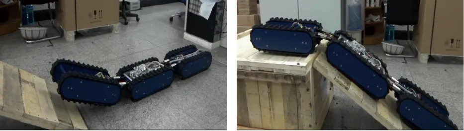
Fig.20 Three-linked tracked rescue robot climbs slope
(2) Cross obstacles
Fig.21 and Fig.22 show the test of crossing obstacles. Each segment of the robots is 500mm in length. The two-linked tracked rescue robot is able to clime 400mm-high obstacles and cross 400mm-wide trench. And the three-linked tracked rescue robot can climb 300mm-high obstacles because of its heavier weight.

Fig.21 Two-linked tracked rescue robot crosses obstacles

Fig.22 Three-linked tracked rescue robot crosses obstacles
(3) Field tests
As illustrated in Fig.23, field tests are carried out at a collapsed house in the national training base for urban search and rescue. Fig.24 shows a test on the traveling ability of the robot over the rubbles of small stones and rocks. The robot can travel smoothly on them. Fig.25 shows a test of crossing obstacles. The stone is about 200mm high and the trench is about 300mm wide. The tests validate the mobility of the rescue robot.

Fig.23 Image of the test field

Fig.24 Traveling on rubble

Fig.25 Crossing obstacles
4.2 Cutting ability test
The cutting process can be divided into four steps: (1) the manipulator reachs out from the front segment; (2) the cutter extends by rotating around joint 1; (3) the cutter rotates around joint 2 to adjust its posture; (4) the cutter starts working. When cutting obstacles, the cutter feed motion is realized by rotating around joint 1. The results illustrated in Fig.26 show that the cutter is able to cut through 10mm diameter steel bars within 2.5 minutes.

Fig.26 Image of cutting test
4.3 Jack-up ability test
Fig.27 presents the image of jack-up ability test. The box loaded on the jack mechanism weighs about 300kg. The jack mechanism can lift the box up from 70mm to 400mm. When the driving motor is power off, the jack mechanism is able to support the load steadily.

Fig.27 Image of jack-up test
5 Conclusion
Two novel rescue robots including a cutter robot and a jack robot which are aimed to cut through obstacles and jack up heavy load in narrow debris are developed. Composed of two crawler vehicles connected by active joint mechanism, the two rescue robots have high mobility and adaptability on irregular terrain in disaster sites. Configuration of the rescue robots can be changed by adding more segments according to practical requirement. The cutter robot is able to cut through 10 mm diameter steel bars. And the jack robot can lift up 300 kg load from 70 mm to 400 mm by using a novel type of jack mechanism which adopts the structure of multiple layers screw sleeves. The experimental results and field tests make us believe that the two rescue robots can play a role in disaster relief operations. In the future, our research will focus on the improvement of remote control distance, battery life and other new portable rescue tools to make the rescue robots more practical.
[ 1] Micire M. Analysis of the Robotic-assisted Search and Rescue Response to the World Trade Center Disaster: [Master dissertation]. Florida: University of South Florida, 2002. 19-30
[ 2] Takayama T, Hirose S. Development of “Souryu I & II”. Journal of Robotics and Mechatronics, 2003, 15(1): 61-69
[ 3] Masayuki A, Takayama T, Hirose S. Development of “Souryu-III”: connected crawler vehicle for inspection inside narrow and winding spaces. In: Proceedings of 2004 IEEE/RSJ International Conference on Intelligent Robots and Systems, Sendai, Japan, 2004. 52-57
[ 4] Guarnieri M, Takao I, Fukushima E F, et al. HELIOS VIII search and rescue robot: design of an adaptive gripper and system improvements. In: Proceedings of the 2007 IEEE/RSJ International Conference on Intelligent Robots and Systems, San Diego, USA, 2007. 1775-1780
[ 5] Tsukagoshi H, Tanaka T, Kitagawa A, et al. Development of a jack-up mobile robot for narrow space: Bari-bari-I. Transactions of the Japan Society of Mechanical Engineers, 2004. 2P1-H-42 (In Japanese)
[ 6] Tsukagoshi H, Kitagawa A, Ito M, et al. Bari-bari-II: jack-up rescue robot with debris opening function. In: Proceedings of the 2008 IEEE International Conference on Robotics and Automation (ICRA 2008), Pasadena, USA, 2008. 2209-2210
[ 7] Tsukagoshi H, Ito M, Kiryu I, et al. Development of jack-up mobile robot with debris opening function. Transactions of the Japan Society of Mechanical Engineers, 2006. 2P2-D12 (In Japanese)
[ 8] Tanaka J, Suzumori K, Takata M, et al. A mobile jack robot for rescue operation. In: Proceedings of the 2005 IEEE International Workshop on Safety, Security and Rescue Robotics (SSRR 2005), Kobe, Japan, 2005. 99-104
[ 9] Tanaka J, Mori M, Suzumori K, et al. A mobile cutter robot for rescue operations. In: Proceedings of SICE Annual Conference 2005, Okayama, Japan, 2005. MA2-15-1
[10] Mori M, Tanaka J, Suzumori K, et al. Field test for verifying the capability of two high-powered hydraulic small robots for rescue operations. In: Proceedings of the 2006 IEEE/RSJ International Conference on Intelligent Robots and Systems (IROS 2006), Beijing, China, 2005. 3492-3497
Zang Xizhe, born in 1975. He received his Ph.D. degree from Harbin Institute of Technology, Harbin, P.R.China in 2005. He also received his Master degree from Harbin Institute of Technology in 1999. His research focuses on special robot, teleoperation robot and passive dynamic walking robot.
10.3772/j.issn.1006-6748.2015.04.004
①Supported by the National High Technology Research and Development Programme of China (No. #2012AA041505).
②To whom correspondence should be addressed. E-mail: zangxizhe@hit.edu.cn Received on July 3, 2014, Wang Jibin, Liu Yixiang
 High Technology Letters2015年4期
- High Technology Letters的其它文章
- Magnetometer calibration algorithm based on ellipsoid constraint①
- Study and application of vibrating wire strain gauge in monitoring cable tension of FAST cable-net①
- Service optimization in programmable cloud network①
- Motion mechanism analysis of two contacting rollers①
- Design of bilayer lengthened LDPC codes over expanded graph for relay channels①
- Effect of laser heating on the microstructure and hardness of TRIP590 advanced high strength steel used for roll forming①