
Analysis and implementation of FURLS algorithm for active vibration control system with positive feedback①
2015-04-17 05:33:39GaoZhiyuan高志远ZhuXiaojinZhangHeshengLuoCongLiMingdong
High Technology Letters 2015年2期
关键词:志远
Gao Zhiyuan (高志远), Zhu Xiaojin, Zhang Hesheng, Luo Cong, Li Mingdong
(School of Mechatronic Engineering and Automation, Shanghai University, Shanghai 200072, P.R.China)
Analysis and implementation of FURLS algorithm for active vibration control system with positive feedback①
Gao Zhiyuan (高志远), Zhu Xiaojin②, Zhang Hesheng, Luo Cong, Li Mingdong
(School of Mechatronic Engineering and Automation, Shanghai University, Shanghai 200072, P.R.China)
While positive feedback exists in an active vibration control system, it may cause instability of the whole system. To solve this problem, a feedforward adaptive controller is proposed based on the Filtered-U recursive least square (FURLS) algorithm. Algorithm development process is presented in this paper. Real time active vibration control experimental tests were done. The experiment results show that the active control algorithm proposed in this paper has good control performance for both narrow band disturbances and broad band disturbances.
adaptive control, active vibration control, Filtered-U recursive least square (FURLS) algorithm
0 Introduction
Active vibration control has been a hot topic during the last two decades[1-5]. Many algorithms have been proposed with the positive feedback effect neglected. Most of them are based on the Least Mean Square (LMS) algorithm[6], such as Filtered-X LMS (FXLMS) algorithm[7, 8]and filtered-V LMS (FVLMS) algorithm[9]. However, positive feedback exists in most of the mechanical vibration control system. It may not be neglected in most situations, as it may result in system instability and system crashes[10-12].
To overcome these problems, a novel active vibration control algorithm based on Filtered-U recursive least square (FURLS) algorithm is proposed in this study. Section 1 introduces a typical mechanical active vibration control system, and gives the discrete model of this mechanical vibration control system. Section 2 gives the FURLS based adaptive control algorithm’s development process. Section 3 illustrates the experiment platform of the system identification results and vibration suppression experiment results. Section 4 gives the conclusions.
1 Description of an active vibration control system
1.1 Active vibration control system with positive feedback
A typical mechanical active vibration control system is shown in Fig.1. The system is consisted of five stainless steel discs connected together by springs. The uppermost one and the lowest one are rigidly connected. The actuators are inertial actuators which are used to output disturbances and control forces. Acceleration sensors are used to measure the error signal and the reference signal. Different control paths could be defined corresponding to the actuators and sensors. The disturbance in this system is input by the inertial actuator located on the bottom, the control actuator on the top would produce a positive feedback force while it tries to suppress the unwanted disturbances. Such active vibration control system can be described in Fig.2.

Fig.1 Schematic diagram of a mechanical active vibration control system

Fig.2 Block diagram of the active vibration control system
1.2 System model description
The secondary path can be expressed as
(1)
here
(2)
(3)
The positive feedback path can be expressed as
(4)
where
(5)
(6)
The primary path can be expressed as
(7)
here
(8)
(9)
The reference path can be expressed as
(10)
where
(11)
(12)
The controller can be expressed as
(13)
here
(14)
(15)
r(t) represents the disturbance. Then the controller input is shown as
u(t)=x(t)+xf(t)
(16)
2 Control algorithm development
A novel adaptive control algorithm will be developed based on the FURLS algorithm. A priori output is given as follows:
(17)
here
(18)
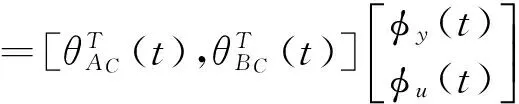
φT(t)=[-y(t),…,-y(t-nAC+1), u(t+1),…,u(t-nBC+1)]
(19)
Then
(20)
A priori output of the secondary path is
(21)
A posteriori output of the secondary path is
ys(t+1)=ys(t+1|θ(t+1))
(22)
while
e(t+1)=d(t+1)+ys°(t+1)
(23)
A priori and a posteriori adaptation error can be defined as
ν°(t+1)=-d(t+1)-ys°(t+1)
(24)
v(t+1)=-d(t+1)-ys(t+1)
(25)
The algorithm can be deduced with the following assumptions:
(1) The disturbance r(t) is bounded, W(z-1) is asymptotically stable, then x(t) is bounded.
(26)


(27)
where

(28)
(29)

(30)
(31)
while the optimal filter is replaced by the adaptive filter,
ys(t)=S(z-1)y(t)
(32)
y(t+1)=y(t+1|θ(t+1))=θT(t+1)φ(t)
(33)
The prediction error can be defined as

(34)
Then the posteriori adaptation error can be expressed as
v(t+1)=-d(t+1)-ys(t+1) =S(z-1)ε(t+1)
(35)
And
(36)
From Eq.(20), one can be got:
(37)
From Eqs(33) and (34), one can be got:

(38)
Substitute it into Eq.(37),
(39)
Then
(40)

φf(t)=Pf(z-1)φ(t)
(41)
(42)
RLS algorithm can be adopted as a parameter update algorithm:
θ(t+1)=θ(t)+F(t)ψ(t)ν(t+1)
(43)
(44)
(45)
The stability condition and convergence condition are:
(46)
which is a strictly positive real transfer function.
3 Experiment
3.1 Experiment platform
The above mechanical vibration system is representative for many applications. A set of devices and instruments are employed to develop a vibration control experiment platform to test the proposed algorithm, as shown in Fig.3. The Matlab-xPC is used for real time vibration control experiments. An NI PCI-1200 card is inserted into the target PC. The sampling frequency is 1000 Hz. The host PC is used to store the control data for further analysis. Also, for a vibration control system, a power amplifier and a charge amplifier are employed to control the force output and sensor signal transformation.
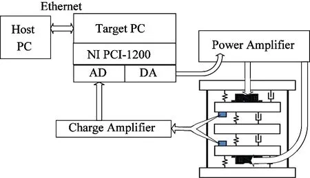
Fig.3 Diagram of the experiment platform
The photograph of the whole experiment platform is shown in Fig.4.

Fig.4 Photograph of the experiment platform
3.2 System identification
As shown in Section 2, to apply the proposed active vibration control algorithm, the model of the secondary path and the positive feedback path should be identified. The identification method used in this paper is output error with extended prediction model algorithm. The algorithm is applicable for the following system:
(47)
The identification process can be summarized as
(48)
φT(t)=[-y(t),…,-y(t-nA+1), u(t-d),…,u(t-d-nB+1),ε(t), …,ε(t-nH+1)]
(49)
where
nH=max(nA,nC)
(50)

(51)

(52)

(53)

(54)
The identification of the secondary path and the positive feedback path were implemented using a pseudo-random binary sequence as the excitation signal. For the identification of the secondary path, the output is the acquired data from the error sensor. As for the positive feedback path, the output is the data picked by the reference sensor.
The identified frequency model of the secondary path and the positive feedback path is shown in Fig.5, the dotted curve is the frequency characteristic for the secondary path, and the solid curve is the frequency characteristic for the positive feedback path. For secondary path, there are several low damped vibration modes: the first order vibration mode is at 44.86Hz with a damping of 0.0080, the second order vibration mode is at 83.94Hz with a damping of 0.0104 and the third order vibration mode is at 114.92Hz with a damping of 0.0080. For positive feedback path, there are also several low damped vibration modes: the first order vibration mode is at 43.8Hz with a damping of 0.0438, the second order vibration mode is at 83.83Hz with a damping of 0.0089 and the third order vibration mode is at 114.71Hz with a damping of 0.0079

Fig.5 Frequency model of secondary path and positive feedback path
3.3 Experiment results
At each sampling time, the proposed adaptive control system implements the following procedures:
(1) Get the measured u(t+1) through the reference sensor, as well as the measured error signal through the error sensor;
(2) Use Eq.(19) and Eq.(41) to calculate φ(t) and φf(t) respectively;
(3) Update θ(t+1) using RLS algorithm as shown from Eq.(43) to Eq.(45);
(4) Use Eq.(33) to calculate the controller output and apply the calculated output into the vibration control system.
A control performance index (CPI) is defined as
(55)
here d(i) is the output of the error sensor before the active vibration control is applied. And e(i) is the output of the error sensor while the active vibration control is applied. While the vibration of the system is suppressed, CPI is negative. While the controller fails to suppress the vibrating system, CPI is positive.
Three type disturbances are applied to test the control performance of the proposed algorithm. While the disturbance is a sinusoidal signal, the control time history is shown in Fig.6. The active vibration control is applied to the vibrating mechanical system at 50 seconds. The structural vibration is suppressed to a great extent very quickly. The signal acquired by the reference sensor is shown in Fig.7. The controller output calculated by the proposed algorithm is shown in Fig.8. Fig.9 shows the controller weight convergence curve for θ. Fig.10 shows power spectral density comparison of control on and control off. CPI for a sinusoidal disturbance is -69.7dB. That means for most of disturbances occurred in factories, the proposed method could get very good control performance and fast convergence speed.
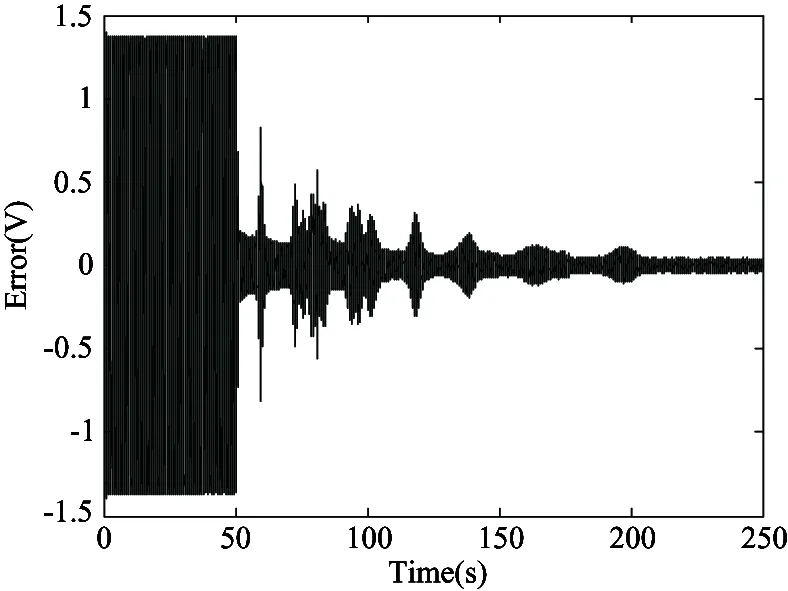
Fig.6 Control time history for a sinusoidal disturbance

Fig.7 Reference signal plot for a sinusoidal disturbance

Fig.8 Control output for a sinusoidal disturbance
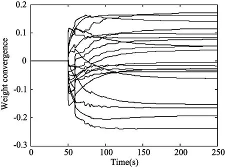
Fig.9 Controller weight convergence curve for a sinusoidal disturbance
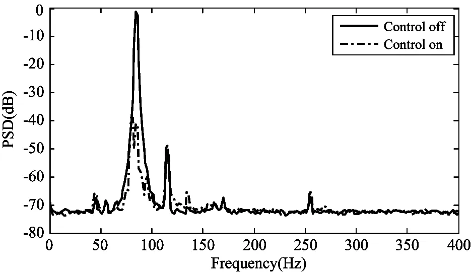
Fig.10 PSD comparison of control on and control off for a sinusoidal disturbance
While a narrow band disturbance with two sinusoidal components is applied, the situation is different, as shown in Fig.11, the control performance get worse. But the proposed algorithm still converge and provide a CPI=-32.4dB, which is still a very good control performance index. Fig.12 shows the reference signal plot. Fig.13 shows the controller output. Fig.14 shows the controller weight convergence curve. And the power spectral density comparison of control on and off is shown in Fig.15.

Fig.11 Control time history for a narrow disturbance with two sinusoidal components
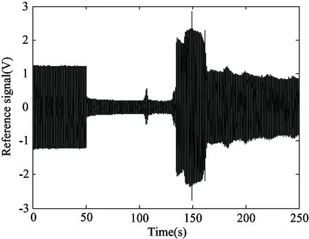
Fig.12 Reference signal plot for a narrow band disturbance with two sinusoidal components

Fig.13 Control output for a narrow band disturbance with two sinusoidal components
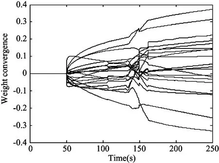
Fig.14 Controller weight convergence curve for a narrow band disturbance with two sinusoidal components
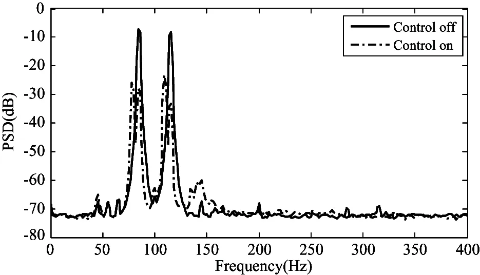
Fig.15 PSD comparison between control on and off for a narrow band disturbance with two sinusoidal components
To further illustrate the effectiveness of the proposed algorithm, a broad band disturbance is applied into the system. The same experiment protocol is applied and an active vibration control is imposed in the vibrating mechanical vibration control system at 50s. The control time history is shown in Fig.16. The reference signal is shown in Fig.17. The controller’s output is shown in Fig.18. Fig.19 shows the controller weight convergence curve. Fig.20 shows power spectral density comparison of control on and off. The CPI of -16.6dB means even for the disturbances which seldom occurs in actual situations, and make the control problem more challenge, the proposed method could also give very good control performance.
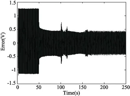
Fig.16 Control time history for a broad band disturbance

Fig.17 Reference signal plot for a broad band disturbance
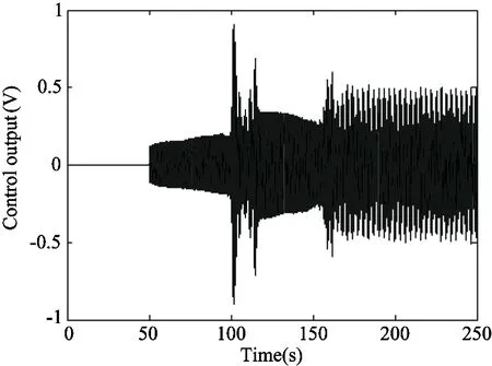
Fig.18 Control output for a broad band disturbance

Fig.19 Controller weight convergence curve for a broad band disturbance

Fig.20 PSD comparison of control on and control off for a broad band disturbance
4 Conclusion
A Filtered-U recursive least square (FURLS) algorithm based active vibration control algorithm is presented in this paper for mechanical active vibration control system with inherent positive feedback coupling. An algorithm develop process is presented. An active vibration control experiment platform is constructed and the real time experiments are implemented. The experiment results show that the proposed control algorithm is feasible with good control performance and fast convergence speed.
Acknowledgment
This study is sponsored by program of National Natural Science Foundation of China (No. 90716027, No.51175319), Innovation program of Shanghai Municipal Education Commission (No.13ZZ075), and Shanghai Key Laboratory of Power Station Automation Technology. Special thanks go to Professor I.D. Landau, Professor Luc Dugard, Mr. Castellanos silva, Abraham and Mr. Airimitoaie, Tudor-bogdan for their kind help and support.
[ 1] Ji C Y, Li H J, Meng Q M. Active control strategy for offshore structures accounting for AMD constraints. High Technology Letters, 2004, 10(4): 63-68
[ 2] Ji C Y, Chen M L, Li S S. Vibration Control of Jacket Platforms with Magnetorheological Damper and Experimental Validation, High Technology Letters, 2010, 16(2): 189-193
[ 3] Huang Q Z, Gao S W, Gao Z Y, et al. Study and verification of an online secondary path identification algorithm for adaptive filtering based control of structural vibration. Chinese High Technology Letters, 2012, 22(1): 61-67 (In Chinese)
[ 4] Alma M, Martinez J J, Landau I D, et al. Design and tuning of reduced order H-infinity feedforward compensators for active vibration control. IEEE Transactions on Control Systems Technology, 2012, 20(2): 554-561
[ 5] Shin C, Hong C, Jeong W B. Active vibration control of beam structures using acceleration feedback control with piezoceramic actuators. Journal of Sound and Vibration, 2012, 331(6): 1257-1269
[ 6] Widrow B, Glover J R, Mccool J M, et al. Adaptive noise cancelling: Principles and applications. Proceedings of the IEEE, 1975, 63(12): 1692-1716
[ 7] Huang Q Z, Zhu X J, Gao Z Y, et al. Analysis and implementation of improved multi-input multi-output filtered-X least mean square algorithm for active structural vibration control, Structural Control and Health Monitoring, 2013, 20(11): 1351-1365
[ 8] Ardekani I T, Abdulla W H. Theoretical convergence analysis of FxLMS algorithm. Signal Processing, 2010, 90(12): 3046-3055
[ 9] Lu J, Shen C, Qiu X, et al. Lattice form adaptive infinite impulse response filtering algorithm for active noise control. Journal of the Acoustical Society of America, 2003, 113(1): 327-335
[10] Wang Z, Li J. New features of time-delayed positive feedbacks in vibration control. Lixue Xuebao/Chinese Journal of Theoretical and Applied Mechanics, 2010, 42(5): 933-942
[12] Li Q S, Fang J Q, Jeary A P, et al. Decoupling control law for structural control implementation. International Journal of Solids and Structures, 2001, 38(34-35): 6147-6162
Gao Zhiyuan, born in 1986. Currently he is a lecturer at Shanghai University. He received his Ph.D degree from Shanghai University in 2014 and his B.S. degree from Harbin Institute of Technology in 2008. His research interests include active vibration and noise control, adaptive control and embedded systems.
10.3772/j.issn.1006-6748.2015.02.008
①Supported by the National Natural Science Foundation of China (No. 90716027, 51175319).
②To whom correspondence should be addressed. E-mail: mgzhuxj@shu.edu.cn Received on Feb. 4, 2014
猜你喜欢
Chinese Physics B(2024年2期)2024-02-29 09:17:44
Chinese Physics B(2023年10期)2023-11-02 08:10:54
大众文艺(2022年24期)2023-01-09 09:27:16
Chinese Physics B(2022年11期)2022-11-21 09:27:42
Chinese Physics B(2022年4期)2022-04-12 03:44:16
电影文学(2021年17期)2021-10-14 08:56:50
Chinese Physics B(2021年7期)2021-07-30 07:38:10
作文评点报·低幼版(2020年42期)2020-12-14 03:53:59
Chinese Physics B(2019年6期)2019-06-18 05:42:14
小学生作文·小学低年级适用(2016年1期)2016-03-07 08:22:24
 High Technology Letters2015年2期
- High Technology Letters的其它文章
- Improving wavelet reconstruction algorithm to achieve comprehensive application of thermal infrared remote sensing data from TM and MODIS①
- Security analysis of access control model in hybrid cloud based on security entropy①
- Multi-sensor federated unscented Kalman filtering algorithm in intermittent observations①
- MPLPK: A mobile path localization protocol based on key nodes①
- Research on suppress vibration of rotor misalignment with shear viscous damper①
- Design and development of real-time query platform for big data based on hadoop①