Structure Design of Shaped Charge for Requirements of Concrete Crater Diameter
(郭坚), (何勇), (肖强强), (黄正祥), (刘蓓蓓)
School of Mechanical Engineering, Nanjing University of Science and Technology, Nanjing 210094, P.R. China (Received 18 November 2014; revised 2 January 2015; accepted 12 March 2015)
Structure Design of Shaped Charge for Requirements of Concrete Crater Diameter
GuoJian(郭坚),HeYong(何勇)*,XiaoQiangqiang(肖强强),HuangZhengxiang(黄正祥),LiuBeibei(刘蓓蓓)
School of Mechanical Engineering, Nanjing University of Science and Technology, Nanjing 210094, P.R. China (Received 18 November 2014; revised 2 January 2015; accepted 12 March 2015)
When shaped charge penetrats into concrete, crater diameter must meet certain requirements. By using theories of shaped jet formation and crater diameter growth during jet penetrating concrete, we revealed the thresholds of the velocity and diameter of jet head, and therefore obtained the related structure parameters of top liner, so that shaped charge structure was developed. We built a ∅60 mm copper liner and a ∅142 mm Ti-alloy liner which followed the rules of 0.6 cal and 0.7 cal in-crater diameter. respectively. X-ray experiment and penetration test results showed that the parameters of jet head were consistent with the results of theoretical analysis. The in-crater diameter of ∅60 mm shaped charge reached 36 mm, and the ∅142 mm one reached 100 mm. They both met the design requirements.
shaped charge; crater diameter; structure design
0 Introduction
As the application area of shaped charge is expanding to some special fields, including precursory charge of tandem warhead[1], and petroleum perforation bullet[2], other than shaped charge penetration depth requirements, additional condition that penetration crater diameter must be as large as possible is also demanded. Enlarging penetration crater diameters can increase damage power of shaped charge.
Many scholars at home and abroad have focused on structural design and optimization for shaped charge to increase jet penetrating crater diameter. Huerta et al.[3]used numerical simulation to structurally design and optimize single cone shaped charge and verified it by experiments. Xiao et al.[4]designed double material composite of jet shaped charge to increase crater diameter. Zhou Quan[5]conducted multi-objective optimization design based on orthogonal test to reach two objectivs of penetration depth and crater diameter, and the latter was selected as the main objective function. Ma Jianfu[6]investigated the influence of structure and materials of shaped charge on penetration depth and crater diameter in the process of jet penetraton.
We developed a structure of top liner to increase crater diameter based on the theory of shaped jet formation and crater diameter growth theory during jet penetration. Then we designed shaped charge structure and and tested it.The experiments verified that the method could be applied to structure design of large crater diameter shaped charge.
1 Theoretical Analysis
1.1 Structure design
Szendrei/Held equations provided the relationship between penetration crater diameter and velocity & diameter of shaped charge jet[7-11]
(1)
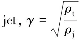
Eq.(1)showsthatthevelocityanddiameterofjetheadshouldsatisfythefollowingrelations
(2)
wherevTisthevelocityofjethead,DTthediameterofjethead,andDTcthecraterdiameterofconcrete.

Fig.1 Schematic of liner collapse
Fig.1deliberatestheschematicoflinercollapse.Sincethedistancebetweentheelementsatthetopofthelinerandchargeaxisisshort,elementsarequicklycrushedtotheaxisdrivenbyexplosivedetonation.Consideringscatteringangleδ≈0°andcollapseangleβ≈α,basedontheformationtheoryofshapedchargejet,thevelocityandthemassofjetheadcanbesimplifiedas[12]
(3(a))
(3(b))
whereαisthehalfconeangleofchargeelement,vT0thecollapsevelocityofelementsatthetopoftheliner,andmT0themassofelementsatthetopoftheliner.
IfyisthedistancefromelementofthetoplinertotheaxisandΔTthewallthicknessofelement,therelationshipbetweenjetheaddiameterandwallthicknessofthetoplinercanbeobtainedbygeometryas
(4)
Supposethatthemoveofelementisonlydrivenbyexplosiveone-dimensionalprojection,andthattheinfluenceoflateralrarefactionwavesandeffectofelementscanbeignored.Sincethemetalisnotrigidbody,surfacepressureofprojectileisactuallynotsohighanddetonationwaveobliqueimpactsliner,collapsevelocityofelementattoplineris
(5)
whereφistheangleformdetonationwavefronttotangentplaneoflinerelement,lTthelengtheffectivechargecorrespondingtolinerelement,ρethedensityoftheexplosive,andDthe detonation velocity.
To charge in top liner, we have
(6)
whereRkischargeradius.
SubstituteEqs.(5,6)intoEq.(3(a)),thevelocityofjetheadcanbeobtained.ThensubstituteEqs.(3(a),4)intoEq.(2),weobtain
(7)
WhenDTcisthecraterdiameter,therelationshipofΔT,α,φandyshouldsatisfiesEq.(7).Ifanythreeofthemareknown,thefourthcanbecalculated.Therefore,byusingtheparametersofthetopliner,structurecanbedesigned,soastoobtaintherequiredcraterdiameteronconcrete.
1.2 Calculation verification
1.2.1 Cooper liner structure
The diameter of shaped charge is ∅60 mm and crater diameter on concrete is 0.6 times the charge diameter, that isDTc=36mm. The explosive is JH-2,withρe=1.7g/cm3,D=8.4mm/μs. The martial of liner is OFHC withρj=8.93g/cm3. Concrete is C35 withρt=2.4g/cm3andRt=68MPa[13].
ThechargestructureisKtype.Halfconeangleisα=60°.Thedistancefromelementatthetoplinertoaxisyis1.6mm. The diameter of waveform regulator is ∅52 mm and the angle of incidence of detonation wave isφ=0°.
WecangetΔT=1.74mmby Eq(7). Through parameters of element at the top liner,vT=5.35mm/μsandDT=2.4mmcan be obtained by Eq. (3(a)) and Eq.(4) respectively. To simplify the calculation during inverse design of the top structure of liner, we approximately setδ≈0,β≈α,sojetheadvelocityoftheactualchargestructureshouldbelowerthanthecalculatedvalue,andtheheaddiameterishigherthancalculationvalues.
Accordingtothestructureoflinertopbyinversedesign, ∅60mmshapedchargestructureisshowninFig.2.

Fig.2 Inversion structure of ∅60 mm shaped charge liner
1.2.2Ti-alloylinerstructure
Thediameterofshapedchargeis∅142mmandcraterdiameteronconcreteis0.7timesthechargediameter,thatisDTc=99mm. The explosive is Octol, withρe=1.78g/cm3andD=8.48mm/μs. The martial of liner is Ti-alloy withρj=5.6g/cm3. Concrete is C40 withρt=2.4g/cm3andRt=80MPa[13].
The charge structure is K type. The half cone angle isα=48°.Thedistancefromelementatthetoplinertoaxisyis6mm. The diameter of waveform regulator is ∅132 mm and the angle of incidence of detonation wave isφ=0°.
ΔT=6.48mmcan be calculated by Eq.(7). With parameters of element at the top liner,vT=7.65mm/μsandDT=6mmcan be obtained by Eq.(4(a)) and Eq.(6),respectively.
According to the structure of liner top by inverse design, ∅142 mm shaped charge structure is shown in Fig.3.

Fig.3 Inversion structure of ∅142 mm shaped charge liner
2 Experiment and Analysis
2.1 X-ray experiment
X-ray experiment site layout for ∅60 mm shaped charge is shown in Fig.4. Experiments were conducted four times, and the results are shown in Figs.5—8.
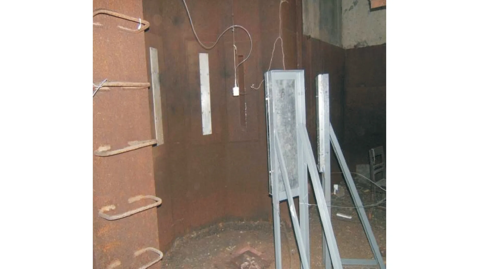
Fig.4 X-ray experiment site

Fig.5 X-ray of the first charge (50 μs, 80 μs)

Fig.6 X-ray of the second charge (40 μs,100 μs)
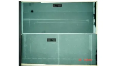
Fig.7 X-ray of the third charge (60 μs, 155 μs)
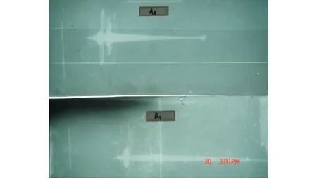
Fig.8 X-ray of the fourth charge (30 μs, 60 μs)
Head velocity of shaped charge jet was about 5 000 m/s. Head diameter was about 3.5 mm. The tail velocity was about 1 265 m/s and the tail diameter was about 14.5 mm by measuring. X-ray showed that the calculation result was basically consistent with the basic X-ray experimental results. Compared with inverse design theoretical results, calculated value of head velocity was higher and head diameter was smaller which is in accordance with the results of the analysis because the theoretical analysis ignores flying angle and crushing angle changes of element at top liner.
2.2 Experiment on crater ability
2.2.1 Cooper liner
Standard C35 concrete target used in test has two kinds of thickness, 0.5 and 1 m. The stand-off is 100 mm (1.7 Cal.). Test site layout is shown in Fig.9. Test was conducted three times. The first and the second target plate thicknesses were 500 mm. The third one was 1 000 mm, and the holes on the concrete are shown in Figs.10—12.

Fig.9 Test site layout of ∅60 mm shaped charge penetrating concrete
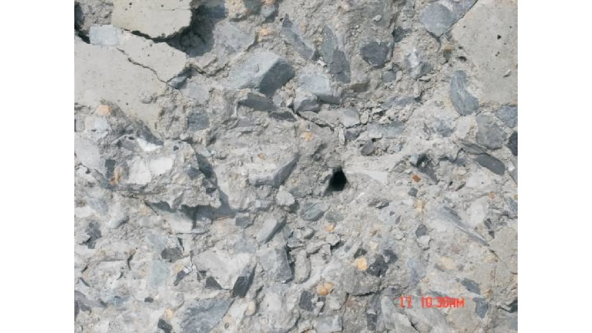
Fig.10 In-crater of the first ∅60 mm shaped charge
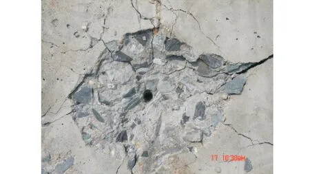
Fig.11 In-crater of the second ∅60 mm shaped charge
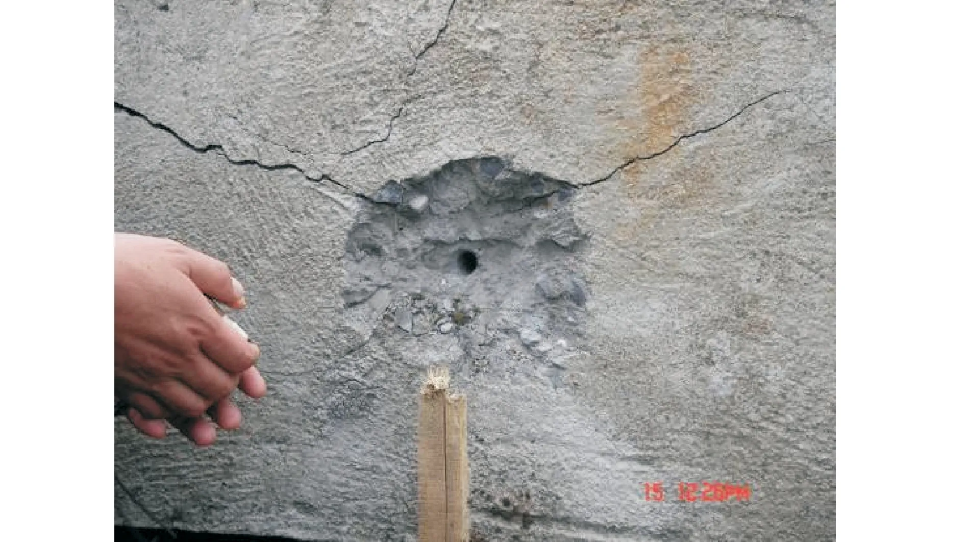
Fig.12 In-crater of the third ∅60 mm shaped charge
The first in-crater diameter was 35 mm, and the out-crater diameter was 15 mm. The second in-crater diameter was 36 mm, and the out-crater diameter was 15 mm. The third target thickness was 1 000 mm. The penetration depth was 650 mm, and the in-crater diameter was 35 mm. The test results are shown in Table 1.

Table1 Test results of ∅60 mm shaped charge
When stand-off was 100 mm, the penetration depth of ∅60 mm shaped charge penetrating standard C35 concrete was 650 mm( about 10.8 Cal.) and in-crater diameter was 36 mm (0.6 Cal.), which agreed with the inverse design goal that ∅60 mm shaped charge penetrating diameter on concrete is larger than 0.6 Cal.
2.2.2 Ti-alloy liner
The thickness of standard C40 concrete target used in test was 1.2 m. The stand-off is 307 mm (2.2 Cal.). The in-crater hole on the concrete is shown in Fig.13.

Fig.13 In-crater of ∅142 mm shaped charge
The 1.2 m thick concreter target was penetrated. The in-crater diameter was 100 mm(0.7 Cal.), and the out-crater diameter was 70 mm(0.5 Cal.) which reached the inverse design goal that ∅142 mm shaped charge penetrating diameter on concrete is larger than 0.7 Cal.
3 Conclusions
We analyzed the velocity and the diameter of the jet head when shaped charge jet crater diameter met certain requirements by using the theories of shaped jet formation and crater diameter growth during jet penetrating concrete. The structure parameters of ∅60 mm and ∅142 mm shaped charge were investigated with the required crater diameter. The structure of shaped charge was designed, and the head velocity and diameter were obtained by calculation.
By ignoring flying angle and crushing angle change, the calculated head velocity was higher than the actual value and the calculated head diameter was lower than the actual value, which was confirmed by X-ray experiments. The penetration power experiment indicated that when stand-off was 100 mm, the penetration depth of ∅60 mm shaped charge penetrating standard C35 concrete was 650 mm(about 10.8 Cal.) and in-crater diameter was 36 mm (0.6 Cal.), and ∅142 mm shaped charge penetrated 1.2 m standard C40 concrete and in-crater diameter was 100 mm(0.7 Cal.). The experiment validated our design.
[1] Wang Shuyou. Penetration mechanism of reinforced concrete targets by tandem warhead[D]. Nanjing: Nanjing University of Science and Technology, 2006.(in Chinese)
[2] Liu He, Wang Feng, Wang Yucai, et al. Oil well perforation technology: Status and prospects[J]. Petroleum Exploration and Development, 2014, 41(6): 731-737.(in Chinese)
[3] Huerta M, Vigil M G. Design, analyses, and field test of a 0.7 m conical shaped charge[J]. International Journal of Impact Engineering, 2006, 32(8): 1201-1213.
[4] Xiao Q Q, Huang Z X, Zu X D, et al. Penetration research of jacketed jet into concrete[J]. International Journal of Impact Engineering, 2013, 54: 246-253.
[5] Zhou Quan. Multi-objective optimization design of penetration depth and crater diameter of shaped charge[D]. Nanjing: Nanjing University of Science and Technology, 2007. (in Chinese)
[6] Ma Jianfu. Study on the mechanism of penetrating into concrete using shaped charge structures[D]. Taiyuan: North University of China, 2007. (in Chinese)
[7] Szendrei T. Analytical model of crater formation by jet impact and its application to calculation of penetration curves and hold profiles[C]∥7th Nternational Symposium of Ballistics.Hague,Netherlands:[s.n.],1983: 575-583.
[8] Szendrei T. Link between axial penetration and radial crater expansion in hypervelocity impact[C]∥ 17th International Symposium of Ballistics. Midrand, South Africa:International Ballistics Committee,1998: 25-32.
[9] Held M. Verification of the equation for radial crater growth by shaped charge jet penetration[J]. International Journal of Impact Engineering, 1995, 17(1/2/3): 387-398.
[10]Held M, Huang N S, Jiang D,et al. Determination of the crater radius as a function of time of a shaped charge jet that penetrates water[J]. Propellants, Explosives, Pyrotechnics, 1996, 21(2): 64-69.
[11]Held M, Kozhushko A A. Radial crater growing process in different materials with shaped charge jets[J]. Propellants, Explosives, Pyrotechnics, 1999, 24(6): 339-342.
[12]Wang Ruce, Zhao Guozhi. Projectile terminal effects[M]. Version 1. Beijing: Beijing University of Science and Technology Press, 1993. (in Chinese)
[13]Xiao Q Q, Huang Z X, Zhu C S,et al.Calculation of depth and crater diameter for the supersonic penetration of shaped charge jet into concrete[J]. Propellants, Explosives, Pyrotechnics, 2013, 38(2): 224-231.
(Executive Editor: Zhang Bei)
TJ410.2 Document code:A Article ID:1005-1120(2015)06-0681-06
*Corresponding author: He Yong, Professor, E-mail: yhe1964@njust.edu.cn.
How to cite this article: Guo Jian, He Yong, Xiao Qiangqiang, et al. Structure design of shaped charge for requirements of concrete crater diameter[J]. Trans. Nanjing U. Aero. Astro., 2015,32(6):681-686. http://dx.doi.org/10.16356/j.1005-1120.2015.06.681
 Transactions of Nanjing University of Aeronautics and Astronautics2015年6期
- Transactions of Nanjing University of Aeronautics and Astronautics的其它文章
- Modeling and Identification Approach for Tripod Machine Tools
- Three-Dimensional Planning of Arrival and Departure Route Network Based on Improved Ant-Colony Algorithm
- Prediction of Compressive and Shear Moduli of X-cor Sandwich Structures for Aeronautic Engineering
- Three-Dimensional Reconstructed Finite Element Model for C/C Composites by Micro-CT
- Infrared Heating Technology for Automated Fiber Placement
- Effect of Tip-Blade Cutting on the Performance of Large Scale Axial Fan
