Research on fault diagnosis and fault toleranttechnology of IGBT in active power filters
Cheng GONG,Zhen-xing LIU ,Cui LI,Kai FENG
(1 College of Information Science and Engineering,Wuhan University of Science and Technology,Wuhan 430081,China)
(2Wuhan University of Science and Technology Engineering Research Center of Metallurgical Automation and Detection Technique,Ministry of Education,Wuhan 430081,China)
Research on fault diagnosis and fault toleranttechnology of IGBT in active power filters
Cheng GONG1,2*,Zhen-xing LIU1,2,Cui LI1,2,Kai FENG1,2
(1College of Information Science and Engineering,Wuhan University of Science and Technology,Wuhan 430081,China)
(2Wuhan University of Science and Technology Engineering Research Center of Metallurgical Automation and Detection Technique,Ministry of Education,Wuhan 430081,China)
For the IGBT(Insulated Gate Bipolar Transisto)of active power filter is prone to failurewhichmay result in serious consequences,an idea of detecting and locating the breakdown of IGBT on basis of DSP software and a fault tolerant topology of redundant single bridge arm of active power filter are proposed in this paper.Following the analysis of the algorithm of fault diagnosis of open circuit,a fault tolerant topology of active power filter and a specific implementmethod of fault-tolerant control are provided.Meanwhile,a related simulation model of the control system of active power filter is established on the MATLAB/Simulink simulation platform where the feasibility of this control scheme is verified through simulation experiments.
Active power filter(APF),IGBT,Detecting fault through software,Fault tolerant control
*Corresponding author:Cheng GONG,Master graduate student.
E-mail:gc7223739@163.com
1 In troduction
With the dramatic increase of nonlinear load of power system,which ismainly represented by power electronic devices,problems concerning power quality in terms of voltage fluctuation,flicker and unbalanced,three-phase emerged.Active power filter(APF),basing on three-phase six-switch and being able to dynamically control the harmonic and reactive power compensation,has been widely used[1].
The power semiconductor devices-IGBT in the APF is themost prone to failure after work for a long time with high frequency and under high temperature condition.Yet how to improve its stability and reliability effectively remains a problem.At the same time,the stability and reliability of IGBT determines the reliability of APF,and any failure in IGBT will lead to a breakdown of the whole system,disastrous consequenceswill emerge atworst.In order to enhance the stability and reliability of the system,prolong the time of reliable operation of the APF and buy time for the maintenance of APF after the failure of IGBT APF,fault diagnosis and fault-tolerant control of APF has become a very important subject.With fault-tolerant control of APF being an emerging discipline,few domestic researches have been done on it.It shows good development prospects.In terms of fault-tolerant control of APF,what the domestic and foreign scholars usually do is to reconfigure.the circuit topology structure of active power after the happening of failure and provide a corresponding fault tolerant strategy tomaintain the stability of the system to recover the performance beforehand asmuch as possible[2-4].Literature[3]puts forward a kind of fault-tolerant active power filter on basis of the structure of three-phase four-switch inverter.With this kind of fault-tolerant topology structure,the only thing should be done after failure is to switch a switch,which helps a lot in cost savings.Buta switch of the control algorithm is necessary in the process of fault-tolerant control.Since the APF based on the three-phase four-switch control algorithm is not very perfect now,the compensation effect is no better than the original system.Literature[4]puts forward a kind of open circuit diagnosis and faulttolerant control scheme based on hardware circuit.
Based on the research of scholars both at home and abroad,this article puts forward a kind of IGBT open circuit faults in the detection of APF on basis of DSP software and a fault-tolerant APF control scheme of redundant single bridge arm.When fault in IGBT of APF occurs,the system locates the fault by DSP,removes the fault phase,access the redundant bridge arm into the system,and meanwhile,switches the control signals into the accessed redundant bridge arm.The fault-tolerant APF system,using software to test the location of fault in IGBT,is able to locate faults timely and accurately without the necessity of switching algorithm during the implementation of faulttolerant control.Besides,APF can stillmaintain stable operation,which improves the stability of the system reliability.
2 Analysis of IGBT fau lt detection m ethod based on softw are [5-7]
For the detection of open circuit fault of IGBT in the APF,most previous studies detected faults based on the hardware circuit ormade artificial analysis after gathering failure data from the field.The method of online detecting faults in IGBT on basis of software in the fault-tolerant control of APF has not been used yet.This paper proposes an idea of online detection of faults in IGBT based on DSP software,aiming to detect the location of IGBT failure timely on the basis of saving hardware cost.
The diagnosis of IGBT fault in the three-phase AC motor inverter can be done by current vector path chart.
Through Clarke transform,three-phase alternating current can be transformed into theα,β,static coordinates of two-phase alternating current(AC)iαand iβ.The transforming formula is as follow:i=i


As shown in Fig.1,after the drawing of the current vector diagram with iαand iβbeing the horizontal axis and vertical axis respectively,it can be seen that in the normal steady state,the graph of current vector is circular,the size of the circle is proportional to the load and the scope forφ is(-∞,+∞).
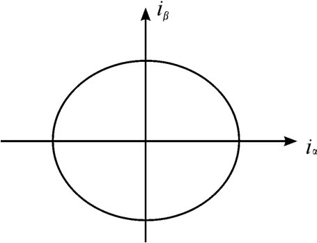
Fig.1 Current path chart under the norm al state
When IGBT open circuit fault occurs,the current vector trajectory has its characteristics.When open circuit fault occurs to T1~T6,the current vector trajectory of them are shown respectively in Fig.2.With the fault analysis of a phase as an example,when IGBT tube T1and T2in a phase respectively disconnects,the current vector diagram as shown in Fig.2(a),(b)will be got.After the T1is disconnected,the positive half cycle is lost in a phase current,and the ia=0 at thismoment.But since the fly-wheel diode which is in reverse parallelwith T1is able to go on the stream with T2,the negative half cycle is notaffected.So the current trajectory can be divided into two parts:When ia<0,the track remains the same,its shape is half arc,and φ∈(-∞,+∞);when ia=0,φ =0,and its shape is a straight line segment.
When T2is disconnected,the situation is the contrary.Without the negative half cycle in the a phase current,and since the fly-wheel diode which is in reverse parallel with T2is able to go on the stream with T1,the positive half cycle is not affected.So when ia>0,the trajectory remains the same,its shape is half arc,andφ∈(-∞,+∞);when ia=0,φ=0,and its shape is a straight line segment aswell.
The method of diagnosing IGBT open circuit fault through vector trajectory in the three-phase AC motor inverter is introduced into the IGBT fault diagnosis in the active power filter.
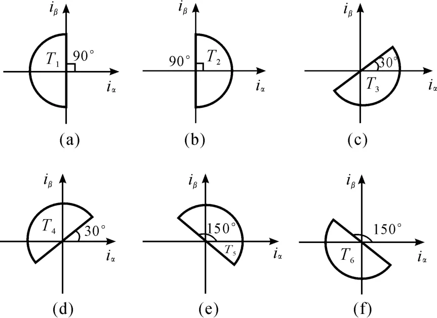
Fig.2 Current trajectory o f T1-T6 under the open-circuit fau lt
After acquiring the experiment data of the IGBT in APF open circuit fault and making vector transformation processing of it on the MATLAB platform,it is found that current vector trajectory in the APF have similar characteristicswith the current vector trajectory in the three-phase motor,IGBT open circuit faults in APF can be diagnosed by current vector trajectory.The current vector diagram with iαand iβbeing the horizontal axis and vertical axis respectively is drawn.As is shown in Fig.3,in the normal steady state,the graph of current vector is hexagon.And through the simulation results,it is shown that the six angles in the hexagon correspond to the six IGBT tubes(T1~T6)in APF.The corresponding relationship is shown in Fig.3.

Fig.3 Current trajectory o f APF under norm al operation
When IGBT open circuit fault occurs in APF,the vector trajectory of the electric current also has its characteristics.The current trajectories of T1~ T6when open circuit fault occur are shown in Fig.4 respectively.With failure in a phase as an example,when IGBT tube T1is disconnected,as the current vector trajectory being shown in Fig.4(a),in which the corresponding angle of T1ismissing on the basis of the normal hexagon.And when IGBT tube T2is disconnected,as the current vector trajectory being shown in Fig.4(b),in which the corresponding angle of T2ismissing on the basis of the normal hexagon.So are the situationswhen IGBT tubes T3~T6are disconnected.
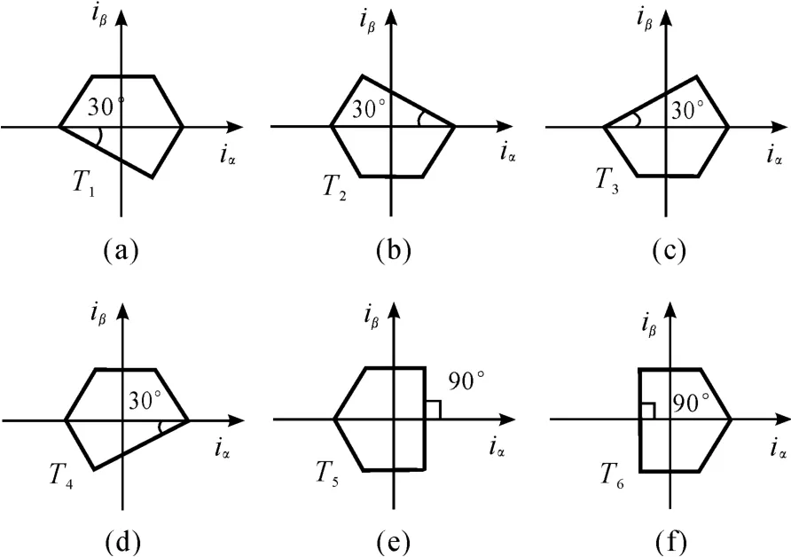
Fig.4 Current trajectory o f T1-T6 under the open-circuit fau lt
According to the above analysis,it can be summarized thatwhen open-circuit fault occurs to various IGBT tubes of APF,the output of current vector trajectory graph share fixed characteristics.When the data of IGBT failure are got,intuitive judge can be made as to the location of the failure from the track diagram through the conduct of vector transformation,the process of which is convenient and intuitive.Two ideas are put forward by the diagnosis of IGBT fault location through APF output current vector trajectory by DSP.Idea 1[7],with the sampling of faultwaveform output providing the fault information,store themapping relationship between the fault location and fault waveform analysis results in the structure of the neural network through neural network learning.Then the system saves the learned neural network through DSP and the IGBT fault location in APF can bemade clear through DSP software on-line detection.
Idea 2,introduce physical quantity slope of half a cycleψ of current vector trajectory,and convert vector trajectory into the physical quantityψwhich DSP can directly identify

During normal operation,the current vector slopeψ is a changing physical quantity in a half cycle,and when the IGBT open circuit fault occurs,the current vector slopeψ is a constant in a half cycle.The relationship between IGBT fault location and half cycle bits of value is shown in Table 1.DSP calculates the collected current and gets half cycle of current slope.Then compare the phase current polarity ikwith the value of DSP in table 1,the location of IGBT tube fault can be identified and the six light-emitting diodes(LEDs)will show the corresponding fault position of IGBT.
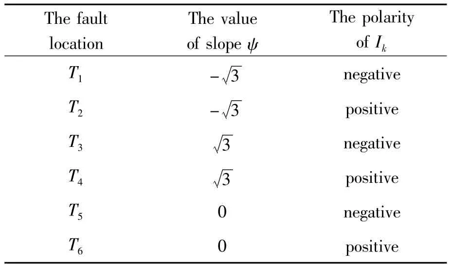
Tab le 1 Fau lt location o f IGBT and the value o fψ

Thismethod does not need to detect the current polarity of phase current ik,instead,DSP only needs to compare the three constants to judge the fault bridge arm in IGBT,which simplifies the algorithm of detecting fault in IGBT through DSP software.The flow chart of themain program of detecting IGBT open-circuit fault through software is shown in Fig.5.
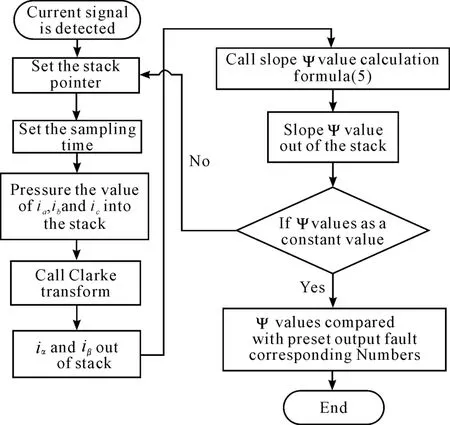
Fig.5 Flow chart o f the m ain p rogram of detecting IGBT open-circuit fault through DSP
3 Realize the fau lt-tolerant control of APF [8]
3.1 APF fault tolerant topology structure
APF fault tolerant topology structure is shown in Fig.6.On basis of the conventional three-phase sixswitch shunt APF,a phase bridge arm and three three-terminal two-way thyristor switches are added.In normal work,a,b,c three-phase accesses system work,three-terminal two-way thyristor switches TRa,TRb and TRc are disconnected,and D1and D2as backup bridge arms are not accessed into the system.APF in this situation is a conventional three-phase sixswitch shunt APF.When the open circuit fault of the APF system occurs,disconnect the fault phase,access the backup bridge arm into APF system under the control of the three-terminal two-way thyristor switches TRa,TRb and TRc to replace the fault phase.Comparing with the backup a complete APF topology,this topology structure reduces the cost under the circumstance of not switching algorithm andmaking the compensation effect the samewith the original system.Besides,when compare with the topology of the APF based on the three-phase four-switch,this topology structure can get better compensation effect without the necessity of switching control algorithm at the cost of a tiny increase of cost.It can be said that this kind of topological structure of redundant single bridge arm combines the advantages of the above two kinds of fault tolerant topology structures and is ideal in terms of both cost and compensation effect.

Fig.6 APF fau lt tolerant topo logical structure of redundant sing le bridge arm
3.2 Realize the fault-tolerant control of APF [9]
In the previous section,the APF fault tolerant topological structurewas introduced.When IGBT failure occurs,disconnect the fault phase and access to the backup bridge arm so as to make the system go on with stable operation in the fault.The key of the faulttolerant control of APF lies in how to disconnect the fault phase and how to access the backup bridge arm when fault happens.
The three-phase bridge arms a,b and c of APF are respectively connected to the normally closed contacts of the three relays.During normal operation,the switches of relays are closed and the three phase bridge arm access into the system.When a failure occurs,DSP drive pulse signal to transmit high level signals to the fault phase relay,control the fault phase relay to disconnect and thus disconnect the fault phase bridge arm.
APF backup bridge arm is disconnected during normal operation,and in the case of open circuit fault,accessed to the circuit to replace the fault phase.A bidirectional thyristor switch is chosen to control the on and off of the backup bridge arm in that a bidirectional thyristor switch is able to exert negative or positive grid signal to conduct.Once the bidirectional thyristor switch begins to conduct,the state of conduction can keep on even if the trigger voltage is disconnected.Only when the current of the first anode A1and the second anode A2is less than tomaintain current or when the voltage polarity of A1and A2changes,the bidirectional thyristor switch will be shut off,when only by triggering voltage again can the bidirectional thyristor switch be conducted.When fault occurs,the trigger latch pulse signal conveys a persistently high level signal to the bidirectional thyristor switch through DSP drive pulse signal until the bidirectional thyristor switch is conducted and the backup bridge arm is accessed.Since the overload ability of a bidirectional thyristor switch is bad,it is necessary to string a fast fuse into the bidirectional thyristor switch TRa,TRb and TRc.In this case,when errors in circuit overload or DSP software lead to awrong trigger,fusing the fast fuse quickly will protect the circuit and switch.The rated current value of the fast fuse should be set 1.5 times of the average current of the bidirectional thyristor.
4 Analysis of the sim u lation
In this article,open circuit fault detection,isolation and fault-tolerant control of IGBT in the APF system which have been shown in Fig.1 aremodeled and simulated on the MATLAB simulation platform.Simulation parameters contains:three-phase grid power source AC voltage with its source amplitude is380 V,50 Hz frequency,the DC side voltage is 800 V,the inverter DC side capacitor is6 000μF,the output filter inductance is 3mh,the load of themain circuit is three-phase rectifier circuit,and the load of the rectifier circuit is 25Ωin resistance and 1 mh in inductance.
This simulation experiment sets the open circuit fault of IGBTmanually,and verifies the quick detection of IGBT open circuit fault by software.After the failure,switch the fault bridge arm and redundant bridge arm and access the control signal into redundant bridge arm and then APF system still can keep stable operation in which the compensation effect is good.
Fig.7(a)is the grid current waveform and current THD(Total Harmonic Distortion)before APF compensation.It can be seen from the diagram that there aremultiple harmonics before compensation,THD is as high as 30.15%and the harmonic content is very high.Fig.7(b)shows the grid currentwaveform and current THD(Total Harmonic Distortion)after the APF compensation.It can be seen from the diagram that the current waveform is reaching sine wave after the compensation,THD reduces to 3.62%.That is,the harmonic content is greatly reduced and the compensation effect is good.Fig.7(c)is the APF DC side voltagewaveform.As can be seen from thewaveform that DC side voltage approximates linear position of 800 V after 0.1 second of oscillation,which corresponds to the DC voltage 800 V given in advance.That reveals that the DC side control algorithm is good in that it can make the DC side stability at a given value so as to ensure the stable operation of system.

Fig.7 The sim u lation resu lts o f before and after compensation
5 Conclusions
This paper brings up with an idea of locating IGBT open circuit fault in the APF based on software testing and further analysis is done on this idea.Meanwhile,fault-tolerant topological structure of redundant the single bridge arm is proposed for fault-tolerant control of APF and the method of switching fault phase and redundant bridge arm when IGBT failure occurs is provided.Finally,a simulation model is built in the MATLAB platform to carry on the simulation test on APF fault-tolerant system.And this simulation experiment proves the feasibility of the diagnosis of fault and fault tolerant topology structure proposed in this paper and their good compensation effect.
Acknow ledgem ents
This paper is supported by National Natural Science Foundation of China(No.61174107).
[1]Jia Yu,Luo An,Tang Jie.Series resonance of active power filter and its engineering application research[J].Electrical applications 2007,26(3):57-59.
[2]Wang Rui,Zhao Jin,Liu Yang.A comprehensive investigation of four-switch three-phase voltage source inverter based on double Fourier integral analysis[J].IEEE Trans on Power Electronics,2011,26(10):2774-2787.
[3]Li gang,Fan Xiaoping,Peng Jinjie.Fault-tolerant active power filter based on 3-phase 4-switch structure[J].Proceedings of the CSU-EPSA),2013,25(30):88-92.
[4]Dong Weijie,Bai Xiaomin,Zhu Ninghui.Research on fault diagnosis and fault tolerant control of active power filters[J].Proceedings of the CSEE,2013,33(18):65-72.
[5]Trabelsi M,Boussak M,Gossa M.Multiple IGBTs open circuit faults diagnosis in voltage source inverter fed induction motor usingmodified slope method[C]//International Conference on Electrical Machines,Rome,2010:1-6.
[6]Chen Dong,Liu Zhenxing.Research on fault diagnosis of PWM rectifier[D].Wuhan:WUST,2012。
[7]Zhang Zuoliang,Tang Chaohui,Hu Zhikun.An Intelligent fault diagnosis system of inverter circuits[J].Computer Engineering& Science,2008,30(3):136-138.
[8]She Yan,Sun Yun lian.Based on DSP implementation of symmetric SVPWM vector control variable frequency speed regulation system[J].Electrical applications,2005,24(4):81-84.
[9]IVONNE Y B,Sun Dan,Liu Xue.Inverter fault tolerant reconfiguration control of permanentmagnet synchronousmotor drives[J].Power electronic technology,2008,42(7):36-36,82-83.
一种有源电力滤波器中IGBT故障诊断与容错控制研究
龚 诚1,2*,刘振兴1,2,李 翠1,2,冯 凯1,2
1.武汉科技大学信息科学与工程学院,武汉 430081
2.武汉科技大学冶金自动化与检测技术教育部工程研究中心,武汉 430081
针对APF(有源电力滤波器)逆变器中IGBT在长期运行时容易出现故障的情况,提出一种基于DSP软件检测定位IGBT故障的方法以及APF容错拓扑结构。分析了IGBT开路故障诊断算法,提出了通过DSP软件程序实现故障诊断的方法,同时给出APF容错拓扑结构以及容错控制实施方法,在Matlab/Simulink仿真平台建立相应的APF控制系统仿真模型,通过仿真实验验证了该控制方案的可行性。
有源电力滤波器;IGBT;软件检测故障;容错控制
10.3969/j.issn.1001-3881.2015.06.019 Document code:A
TN713+ .8
09 October 2014;revised 30 October 2014;accepted 22 December 2014
- 机床与液压的其它文章
- A new test generation algorithm fornon- robust path delay faults
- Time constant of a hydraulic servo valve withdynamic pressure feedback
- Radial fretting character research ofthe shaft-hub of compress impellerbased on virtual orthogonal experiment
- Study on high precision cymometer ofmechanical vibration
- Custom implant design for patients withmandible defects based on rapid prototyping
- Design of car reverse anti- collision warningsystem based on AT89S52

